EP1001230A2 - Systèmes de conditionnement d'air - Google Patents
Systèmes de conditionnement d'air Download PDFInfo
- Publication number
- EP1001230A2 EP1001230A2 EP99121394A EP99121394A EP1001230A2 EP 1001230 A2 EP1001230 A2 EP 1001230A2 EP 99121394 A EP99121394 A EP 99121394A EP 99121394 A EP99121394 A EP 99121394A EP 1001230 A2 EP1001230 A2 EP 1001230A2
- Authority
- EP
- European Patent Office
- Prior art keywords
- refrigerant
- pressure
- discharge
- compressor
- air conditioning
- Prior art date
- Legal status (The legal status is an assumption and is not a legal conclusion. Google has not performed a legal analysis and makes no representation as to the accuracy of the status listed.)
- Withdrawn
Links
Images


Classifications
-
- F—MECHANICAL ENGINEERING; LIGHTING; HEATING; WEAPONS; BLASTING
- F04—POSITIVE - DISPLACEMENT MACHINES FOR LIQUIDS; PUMPS FOR LIQUIDS OR ELASTIC FLUIDS
- F04B—POSITIVE-DISPLACEMENT MACHINES FOR LIQUIDS; PUMPS
- F04B27/00—Multi-cylinder pumps specially adapted for elastic fluids and characterised by number or arrangement of cylinders
- F04B27/08—Multi-cylinder pumps specially adapted for elastic fluids and characterised by number or arrangement of cylinders having cylinders coaxial with, or parallel or inclined to, main shaft axis
- F04B27/14—Control
- F04B27/16—Control of pumps with stationary cylinders
- F04B27/18—Control of pumps with stationary cylinders by varying the relative positions of a swash plate and a cylinder block
- F04B27/1804—Controlled by crankcase pressure
-
- F—MECHANICAL ENGINEERING; LIGHTING; HEATING; WEAPONS; BLASTING
- F25—REFRIGERATION OR COOLING; COMBINED HEATING AND REFRIGERATION SYSTEMS; HEAT PUMP SYSTEMS; MANUFACTURE OR STORAGE OF ICE; LIQUEFACTION SOLIDIFICATION OF GASES
- F25B—REFRIGERATION MACHINES, PLANTS OR SYSTEMS; COMBINED HEATING AND REFRIGERATION SYSTEMS; HEAT PUMP SYSTEMS
- F25B41/00—Fluid-circulation arrangements
- F25B41/20—Disposition of valves, e.g. of on-off valves or flow control valves
- F25B41/24—Arrangement of shut-off valves for disconnecting a part of the refrigerant cycle, e.g. an outdoor part
-
- F—MECHANICAL ENGINEERING; LIGHTING; HEATING; WEAPONS; BLASTING
- F04—POSITIVE - DISPLACEMENT MACHINES FOR LIQUIDS; PUMPS FOR LIQUIDS OR ELASTIC FLUIDS
- F04B—POSITIVE-DISPLACEMENT MACHINES FOR LIQUIDS; PUMPS
- F04B27/00—Multi-cylinder pumps specially adapted for elastic fluids and characterised by number or arrangement of cylinders
- F04B27/08—Multi-cylinder pumps specially adapted for elastic fluids and characterised by number or arrangement of cylinders having cylinders coaxial with, or parallel or inclined to, main shaft axis
- F04B27/14—Control
- F04B27/16—Control of pumps with stationary cylinders
- F04B27/18—Control of pumps with stationary cylinders by varying the relative positions of a swash plate and a cylinder block
- F04B27/1804—Controlled by crankcase pressure
- F04B2027/1809—Controlled pressure
- F04B2027/1813—Crankcase pressure
-
- F—MECHANICAL ENGINEERING; LIGHTING; HEATING; WEAPONS; BLASTING
- F04—POSITIVE - DISPLACEMENT MACHINES FOR LIQUIDS; PUMPS FOR LIQUIDS OR ELASTIC FLUIDS
- F04B—POSITIVE-DISPLACEMENT MACHINES FOR LIQUIDS; PUMPS
- F04B27/00—Multi-cylinder pumps specially adapted for elastic fluids and characterised by number or arrangement of cylinders
- F04B27/08—Multi-cylinder pumps specially adapted for elastic fluids and characterised by number or arrangement of cylinders having cylinders coaxial with, or parallel or inclined to, main shaft axis
- F04B27/14—Control
- F04B27/16—Control of pumps with stationary cylinders
- F04B27/18—Control of pumps with stationary cylinders by varying the relative positions of a swash plate and a cylinder block
- F04B27/1804—Controlled by crankcase pressure
- F04B2027/1822—Valve-controlled fluid connection
- F04B2027/1827—Valve-controlled fluid connection between crankcase and discharge chamber
-
- F—MECHANICAL ENGINEERING; LIGHTING; HEATING; WEAPONS; BLASTING
- F04—POSITIVE - DISPLACEMENT MACHINES FOR LIQUIDS; PUMPS FOR LIQUIDS OR ELASTIC FLUIDS
- F04B—POSITIVE-DISPLACEMENT MACHINES FOR LIQUIDS; PUMPS
- F04B27/00—Multi-cylinder pumps specially adapted for elastic fluids and characterised by number or arrangement of cylinders
- F04B27/08—Multi-cylinder pumps specially adapted for elastic fluids and characterised by number or arrangement of cylinders having cylinders coaxial with, or parallel or inclined to, main shaft axis
- F04B27/14—Control
- F04B27/16—Control of pumps with stationary cylinders
- F04B27/18—Control of pumps with stationary cylinders by varying the relative positions of a swash plate and a cylinder block
- F04B27/1804—Controlled by crankcase pressure
- F04B2027/184—Valve controlling parameter
- F04B2027/1854—External parameters
-
- F—MECHANICAL ENGINEERING; LIGHTING; HEATING; WEAPONS; BLASTING
- F04—POSITIVE - DISPLACEMENT MACHINES FOR LIQUIDS; PUMPS FOR LIQUIDS OR ELASTIC FLUIDS
- F04B—POSITIVE-DISPLACEMENT MACHINES FOR LIQUIDS; PUMPS
- F04B27/00—Multi-cylinder pumps specially adapted for elastic fluids and characterised by number or arrangement of cylinders
- F04B27/08—Multi-cylinder pumps specially adapted for elastic fluids and characterised by number or arrangement of cylinders having cylinders coaxial with, or parallel or inclined to, main shaft axis
- F04B27/14—Control
- F04B27/16—Control of pumps with stationary cylinders
- F04B27/18—Control of pumps with stationary cylinders by varying the relative positions of a swash plate and a cylinder block
- F04B27/1804—Controlled by crankcase pressure
- F04B2027/1863—Controlled by crankcase pressure with an auxiliary valve, controlled by
- F04B2027/1872—Discharge pressure
-
- F—MECHANICAL ENGINEERING; LIGHTING; HEATING; WEAPONS; BLASTING
- F04—POSITIVE - DISPLACEMENT MACHINES FOR LIQUIDS; PUMPS FOR LIQUIDS OR ELASTIC FLUIDS
- F04B—POSITIVE-DISPLACEMENT MACHINES FOR LIQUIDS; PUMPS
- F04B2201/00—Pump parameters
- F04B2201/12—Parameters of driving or driven means
- F04B2201/1204—Position of a rotating inclined plate
- F04B2201/12041—Angular position
-
- F—MECHANICAL ENGINEERING; LIGHTING; HEATING; WEAPONS; BLASTING
- F04—POSITIVE - DISPLACEMENT MACHINES FOR LIQUIDS; PUMPS FOR LIQUIDS OR ELASTIC FLUIDS
- F04B—POSITIVE-DISPLACEMENT MACHINES FOR LIQUIDS; PUMPS
- F04B2205/00—Fluid parameters
- F04B2205/15—By-passing over the pump
-
- F—MECHANICAL ENGINEERING; LIGHTING; HEATING; WEAPONS; BLASTING
- F25—REFRIGERATION OR COOLING; COMBINED HEATING AND REFRIGERATION SYSTEMS; HEAT PUMP SYSTEMS; MANUFACTURE OR STORAGE OF ICE; LIQUEFACTION SOLIDIFICATION OF GASES
- F25B—REFRIGERATION MACHINES, PLANTS OR SYSTEMS; COMBINED HEATING AND REFRIGERATION SYSTEMS; HEAT PUMP SYSTEMS
- F25B2400/00—Component parts or details not otherwise provided for in this subclass
- F25B2400/04—Refrigeration circuit bypassing means
- F25B2400/0403—Refrigeration circuit bypassing means for condensers
-
- F—MECHANICAL ENGINEERING; LIGHTING; HEATING; WEAPONS; BLASTING
- F25—REFRIGERATION OR COOLING; COMBINED HEATING AND REFRIGERATION SYSTEMS; HEAT PUMP SYSTEMS; MANUFACTURE OR STORAGE OF ICE; LIQUEFACTION SOLIDIFICATION OF GASES
- F25B—REFRIGERATION MACHINES, PLANTS OR SYSTEMS; COMBINED HEATING AND REFRIGERATION SYSTEMS; HEAT PUMP SYSTEMS
- F25B2400/00—Component parts or details not otherwise provided for in this subclass
- F25B2400/04—Refrigeration circuit bypassing means
- F25B2400/0411—Refrigeration circuit bypassing means for expansion valves or capillary tubes
Definitions
- the present invention relates to air conditioning systems that utilize refrigerants and a compressor, and particularly to air conditioning systems capable of alleviating excessive increases in refrigerant discharge pressure within a heating circuit.
- a known air conditioning system is disclosed in Japanese Patent Application No. 7-19630 and includes a compressor 1, a cooling circuit 51, a heating circuit 52 and a controller 83, as shown in FIG. 1.
- the cooling circuit 51 includes a condenser 55, a first expansion valve 57 and a heat exchanger 59 provided on a passage extending from a discharge port D to a suction port S of the compressor 1. High pressure refrigerant discharged from the discharge port D of the compressor 1 is drawn through the above respective devices and back to the compressor 1.
- the heating circuit 52 includes a bypass passage 52a that extends from the discharge port D of the compressor 1 to the heat exchanger 59.
- a second expansion valve 63 provided within the bypass passage 52a between the discharge port D and the heat exchanger 59.
- the high pressure refrigerant discharged from the compressor 1 is not directed to the condenser 55, but rather is drawn by the compressor 1 through the second expansion valve 63 and the heat exchanger 59.
- Such a heating circuit 52 is generally known as a hot gas bypass heater.
- the operation of the cooling circuit 51 and the heating circuit 52 is changeably selected by opening and closing selector valves 53a and 53b, which opening and closing operations are performed by the controller 83.
- the air conditioning system must operate in a high pressure state when the heating circuit 52 is utilized.
- An abnormally high-pressure state may be created if the output discharge capacity of the compressor 1 temporarily increases during the operation of the heating circuit 52.
- a refrigerant releasing passage 91 having a pressure relief valve 93 is provided in order to release excess pressure from the heating circuit 52, if an abnormally high pressure state is reached.
- the refrigerant releasing passage 91 is connected to the heating circuit 52 and the cooling circuit 51 and the pressure relief valve 93 can be opened to release the refrigerant from the heating circuit 52 into the cooling circuit 51 when the refrigerant discharge pressure abnormally increases during the operation of the heating circuit 52.
- the refrigerant is released into the cooling circuit 51 which is not used in operation of the heating circuit 52, thereby preventing the discharge pressure at the heating circuit 52 from increasing abnormally.
- the amount of the refrigerant in the heating circuit 52 is reduced and heating performance may be reduced.
- an object of the present invention to quickly and effectively alleviate an abnormally high discharge pressure in an air conditioning system driven by utilizing refrigerant compressed by a compressor, and particularly in an air conditioning system having a hot gas bypass heater as a heating circuit.
- the air conditioning system may include a compressor, a heating circuit, and a refrigerant releaser.
- the compressor has a suction port for drawing refrigerant and a discharge port for discharging compressed refrigerant.
- the heating circuit has a passage that extends from the discharge port to the suction port through a heat exchanger.
- the refrigerant releaser may release the refrigerant from the discharge port to the suction port when the discharge pressure of the refrigerant results a predetermined high-pressure state during the operation of the heating circuit.
- the air conditioning system because the refrigerant releaser is employed for releasing the compressed refrigerant from the discharge port to the suction port when the discharge pressure is in the abnormally high-pressure state, the air conditioning system can solve a problem of insufficient heating performance due to releasing the refrigerant in the heating circuit into the cooling circuit to alleviate the abnormally high-pressure state during operation of the heating circuit.
- an air conditioning system includes a compressor, a heating circuit and a refrigerant releaser.
- the compressor may have a suction port for drawing refrigerant into the compressor and a discharge port for discharging high pressure refrigerant from the compressor.
- the heating circuit may have a passage that extends from the discharge port to the suction port through the heat exchanger.
- the refrigerant releaser may release the refrigerant from the discharge port to the suction port when the refrigerant discharge pressure results a predetermined high-pressure state.
- the refrigerant releaser may release the refrigerant from the discharge port to the suction port to decrease the discharge pressure when the discharge pressure of the refrigerant results the predetermined high-pressure state.
- the compressor discharge pressure is decreased as a direct effect of releasing the refrigerant from the discharge port to the suction port.
- the predetermined high-pressure state of the discharge pressure may be detected based on the difference between the discharge pressure and pressure on the low-pressure side of the air conditioning system.
- the suction pressure of the refrigerant may preferably be utilized as pressure on the low-pressure side for detecting the high pressure state based on the differential pressure.
- an air-tight air conditioning system can be constructed with a relatively simple design.
- the predetermined high-pressure state of the discharge pressure may be detected based on the absolute value of the discharge pressure.
- the system determines that the refrigerant discharge pressure has reached a predetermined high-pressure state and the refrigerant releaser releases the refrigerant from the discharge port to the suction port. Because supply of the high-pressure refrigerant from the discharge port to the heating circuit is immediately cut by the release of the compressed refrigerant, the abnormally high-pressure state of the discharge pressure is quickly alleviated during operation of the heating circuit. The refrigerant released from the discharge port to the suction port by the refrigerant releaser is drawn into the compressor again through the suction port and is compressed and discharged.
- the refrigerant releaser also may have a refrigerant release passage that extends from the discharge port to the suction port and a refrigerant release valve provided on the refrigerant release passage.
- the refrigerant release valve may be opened by an increased pressure difference between the refrigerant discharge pressure and the refrigerant suction pressure. As a result, the refrigerant release passage is opened to connect the discharge port into the suction port and the refrigerant is released from the discharge port to the suction port.
- the refrigerant release passage and the refrigerant release valve are the features that correspond to the refrigerant releaser or the refrigerant releasing means from the discharge port to the suction port, although the interpretation of the refrigerant releaser or the refrigerant releasing means is not limited within such refrigerant release passage and refrigerant release valve.
- variable displacement compressor may be employed to the air conditioning system.
- the variable displacement compressor may have a driving chamber, a suction port for drawing the refrigerant, a discharge port for discharging compressed refrigerant and a driving means such like a swash plate connected to a piston.
- the variable displacement compressor can change the output discharge capacity by changing driving chamber pressure.
- variable displacement compressor can decrease the discharge pressure by releasing the refrigerant from the discharge port into the driving chamber thereby decreasing the output discharge capacity.
- considerable time is required in the variable displacement compressor to decrease the discharge pressure, because it is necessary to release the compressed refrigerant from the discharge port to the driving chamber in order to increase the driving chamber pressure and in order to decrease the compressor output discharge capacity. Therefore, the refrigerant releaser that releases the refrigerant directly from the discharge port to the suction port may preferably be employed to the air conditioning system that utilizes the variable displacement compressor.
- the air conditioning system 100 may include a cooling circuit 151, a heating circuit 152 and a variable displacement compressor 101 as a driving source of both the circuits.
- a refrigerant releaser is shown in FIGS. 3 and 4 but not in FIG. 2 that shows the general structure of the air conditioning system 100. The structure and operation of the refrigerant releaser will be described later in detail.
- Such an air conditioning system 100 may be utilized in a vehicle-mounted air conditioning system.
- a compressor driving shaft 125 may be coupled to and driven by an automobile engine 170, though it is not particularly shown in the drawings.
- the cooling circuit 151 may be driven by high-pressure refrigerant, which is compressed by the compressor 101, and may include a condenser 155, a first expansion valve 157, a heat exchanger 159 and an accumulator 161. These devices may be disposed within a path 151a that extends from a discharge port D to a suction port S of the compressor 101.
- the heat exchanger 159 is generally known as an evaporator.
- the heat exchanger 159 may be arranged side by side with a hot-water heater 171, which circulates hot water from the engine 170 through a pipe 173.
- the heating circuit 152 is driven by high-temperature and high-pressure refrigerant, which is also compressed by the compressor 101, and may include a second expansion valve 163, the heat exchanger 159 and the accumulator 161. These devices may be disposed on a bypass passage 152a for introducing the refrigerant discharged from the discharge port D to the heat exchanger 159. In other words, the heating circuit 152 partially overlaps with the cooling circuit 151.
- Such a heating circuit 152 is generally known as a hot-gas bypass heater.
- a first open/close valve 153a and a second open/close valve 153b may be utilized as switch valves for alternatively actuating the cooling circuit 151 and the heating circuit 152.
- the refrigerant is compressed by the compressor 101 to attain a high temperature and high pressure state.
- This compressed refrigerant is sent to the condenser 155, where heat from the high-temperature refrigerant is dissipated to the outside environment and the refrigerant is liquefied.
- the refrigerant is decompressed by the first expansion valve 157 and sent to the heat exchanger 159 where the refrigerant absorbs outside heat and is gasified.
- the gasified refrigerant is returned to the compressor 101 again through the accumulator 161 for re-circulation throughout the system 100.
- the refrigerant is compressed by the compressor 101 to attain a high temperature and high pressure state.
- the compressed refrigerant is then decompressed by the second expansion valve 163 and sent to the heat exchanger 159, where heat from the compressed refrigerant is dissipated to the outside environment.
- the refrigerant is constantly in a gaseous state while circulating through the heating circuit 152.
- the heating circuit 152 may be used as an auxiliary heater. Heat generated by the heat exchanger 159 during operation of the heating circuit 152 may be used as an auxiliary heating source for the hot water heater described above.
- the heating circuit 152 also may be used to assist the coolant from the engine when the coolant can not provide sufficient heat to start the engine in a low-temperature environment, such as an outside air temperature of -20 °C or so.
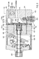
- a representative compressor 101 may include a driving chamber 110 defined within a housing 101a of the compressor 101 and a swash plate that is rotatably supported by the driving shaft 125 in the driving chamber 110.
- the swash plate 130 may be supported by the driving shaft 125 and may rotate together with the driving shaft 125.
- the swash plate 130 is inclined with respect to the driving shaft 125 when the driving shaft 125 rotates and the inclination angle of the swash plate 130 with respect to a plane perpendicular to the axis of rotation of the driving shaft 125 is changeable.
- the peripheral edge portion of the swash plate 130 may be connected to the base portions of pistons 135 by means of movable shoes 131.
- Six pistons 135 in total may be disposed around the driving shaft 125 (however, only one piston is shown in FIG.1 for the sake of convenience) and may be laterally slide within six cylinder bores 109. The circumferential positions of the six cylinder bores 109 are fixed by the compressor housing 101a.
- a suction port 118a and a discharge port 123a are defined in a bottom portion of each the cylinder bore 109.
- a suction valve 118 is positioned to correspond to the suction port 118a and a discharge valve 123 is positioned to correspond to the discharge port 123a.
- Each suction port 118a communicates with a suction chamber 115 and each discharge port 123a communicates with a discharge chamber 120.
- the output discharge capacity of the compressor 101 is determined by the stroke length of the piston 135, which is determined by the degree of change in inclination angle of the swash plate 130 during each cycle. That is, the further the swash plate 130 is withdrawn from the cylinder bore 123 during each cycle, the longer the stroke length of the piston 135 will be. As the stroke length increases, the output discharge capacity of the compressor 101 also increases.
- the suction chamber 115 and the driving chamber 110 may be connected by a bleeding passage 105.
- the discharge chamber 120 and the driving chamber 110 may be connected by a capacity control passage 107.
- a capacity control valve 141 is provided within the capacity control passage 107.
- the capacity control valve 141 is a solenoid valve that includes a valve body 211 and a solenoid 213 and may open or close the refrigerant release passage 107 by exciting or not exciting the solenoid 213. Opening and closing of the capacity control valve 141 are controlled by the controller that is not particularly shown in the drawings.
- the inclination angle of the swash plate 130 is determined, in part, by the difference in pressure on the opposite sides of the piston 135, i.e., the pressure difference between driving chamber pressure and the cylinder bore pressure.
- the above-described opening and closing operation of the capacity control valve 141 can adjust this pressure difference by releasing the high pressure refrigerant from the discharge chamber 120 to the driving chamber 110.
- the capacity control valve 141 is opened to release the high pressure refrigerant in the discharge chamber 121 into the driving chamber 110. Due to resulting increasing in the driving chamber pressure, the swash plate 130 stands and the stroke length of the piston 135 decreases. Therefore, the output discharge capacity also will decrease.
- the capacity control valve 141 is closed so that the refrigerant in the discharge chamber 120 is prevented from being released into the driving chamber 110. As a result, the driving chamber pressure will gradually decrease, the swash plate 130 will move further in the lateral direction and the stroke length of the piston 135 will increase. In this case, the output discharge capacity will increase.
- the capacity control valve 141 When the discharge pressure of the refrigerant results high-pressure state during operation of the heating circuit, the capacity control valve 141 is opened. The refrigerant is released from the discharge chamber 120 into the driving chamber 110 through the capacity control passage 107. The pressure in the driving chamber 110 is increased and the output discharge capacity of the compressor 101 is decreased. Thus, the compressor discharge pressure is decreased and the heating circuit 152 is prevented from being damaged.
- the capacity control valve 141 When the suction pressure of the refrigerant results excessively low-pressure state during operation of the cooling circuit 151, the capacity control valve 141 is opened. The refrigerant is released from the discharge chamber 120 into the driving chamber 110 through the capacity control passage 107. The pressure in the driving chamber 110 is increased and the output discharge capacity of the compressor 101 is decreased. Thus, the compressor suction pressure is increased and the heat exchanger of the cooling circuit 151 is prevented from being frosted.
- the capacity control valve 141 has functions of both the discharge pressure control valve for the heating circuit and the suction pressure control valve for the cooling circuit.
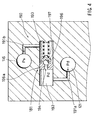
- the refrigerant releaser 190 is provided and has a refrigerant release valve 181, a first refrigerant release passage 191a, a second refrigerant release passage 191b.
- the first refrigerant release passage 191a extends from the discharge opening 121 to the refrigerant release valve 181 and the second refrigerant release passage 191b extends from the refrigerant release valve 181 to the suction opening 116.
- the discharge opening 121 communicates with a first section chamber 192 in the release valve 181 through the first refrigerant release passage 191a. Therefore, the pressure in the first section chamber 192 is equal to the discharge pressure Pd of the refrigerant.
- the suction opening 116 communicates with a second section chamber 193 in the refrigerant release valve 181 through the refrigerant release passage 191b. Therefore, the pressure in the second section chamber 193 is equal to the suction pressure Ps of the refrigerant.
- the first section chamber 192 and the second section chamber 193 are connected by a connecting passage 194 and the connecting passage 194 can be opened or closed by the valve body 196.
- the valve body 196 may be biased toward the first section chamber 192 (to the left in FIG. 4) by a spring 197.
- the biasing force of the spring 197 may be properly determined based on an evaluation as to at which difference between the discharge pressure Pd and the suction pressure Ps the connecting passage 194 should be opened, i.e., which difference between the discharge pressure Pd and the suction pressure Ps reflects the abnormally high-pressure state of the discharge pressure Pd.
- the refrigerant releaser 190 that includes the release valve 181, the first refrigerant release passage 191a and the second refrigerant release passage 191b, the refrigerant is immediately released from the discharge side to the suction side based on the difference between the discharge pressure Pd and the suction pressure Ps when the discharge pressure Pd reaches the abnormally high-pressure state.
- variable displacement compressor In this air conditioning system, the variable displacement compressor is utilized.
- discharge pressure may be alleviated by opening the capacity control valve 141 shown in FIG. 3 thereby releasing the refrigerant from the discharge chamber 120 into the driving chamber 110 to increase the pressure in the driving chamber 110.
- the swash plate 130 stands to decrease the stroke length of the piston 135, thereby decreasing the output discharge capacity and decreasing the discharge pressure.
- the refrigerant is released immediately from the discharge side to the suction side by utilizing the refrigerant releaser 190 to alleviate the high-pressure state of the discharged refrigerant as a direct effect of the release.
- the discharge pressure Pd is released based on the difference between the discharge pressure Pd and the suction pressure Ps and it is unnecessary to employ atmospheric pressure or vacuum pressure as a reference value. Therefore, it is possible to improve airtightness of the air conditioning system.
- condition for opening the refrigerant release valve 181 is arranged based on the operating pressure of the heating circuit that utilizes the relatively high pressure. As the result, the release valve 181 is closed during operation of the cooling circuit that utilizes the relatively low discharge pressure.
- a refrigerant release valve 281 is provided that is opened by utilizing a difference between the discharge pressure Pd and the pressure Pc in the driving chamber 110.
- the discharge pressure is utilized as pressure on the high-pressure side and the pressure in the driving chamber 110 is utilized as pressure on the low-pressure side.
- the refrigerant release valve 281 includes a first section chamber 292, a second section chamber 293, and a third section chamber 295.
- the first section chamber 292 communicates with the discharge opening 121 through a first refrigerant release passage 291a. Therefore, pressure in the first section chamber 292 is equal to the discharge pressure Pd.
- the second section chamber 293 communicates with the suction opening 116 through the second refrigerant release passage 291b. Therefore, pressure in the second section chamber 293 is equal to the suction pressure Ps.
- the third section chamber 295 communicates with the driving chamber 110 shown in FIG. 3 through a driving chamber pressure introducing passage 291c. Therefore, pressure in the third section chamber 295 is equal to the pressure Pc in the driving chamber 110.
- a valve body 296, a differential pressure actuated member 299, and a connecting bar 298 for connecting the valve body 296 and the differential pressure actuated member 299 are formed integrally.
- the compressor discharge pressure decreases in response to such releasing of the refrigerant from the discharge opening 121 to the suction opening 116.
- the biasing force of the spring 297 may be properly determined based on an evaluation as to at which difference between the discharge pressure Pd and the pressure Pc the connecting passage 194 should be opened, i.e., which difference between the discharge pressure Pd and the pressure Pc reflects the abnormally high-pressure state of the discharge pressure Pd.
- variable displacement compressor is used in the above first and second embodiments, a fixed displacement compressor with a constant discharge capacity of the refrigerant can be utilized in stead of the variable displacement compressor.
- pistons for compressing the refrigerant double-ended pistons connected to opposite sides of the swash plate 130 for reciprocation in the compressor can be utilized.
- the refrigerant releaser 190 is provided inside the compressor (within the housing) , the refrigerant releaser 190 can be entirely or partially provided outside the compressor.
- the air conditioning system has the heating circuit and the cooling circuit in the embodiments, the cooling circuit can be omitted, because it is especially during operation of the heating circuit that the high-pressure state of the discharge pressure of the refrigerant becomes a problem.
Landscapes
- Engineering & Computer Science (AREA)
- Mechanical Engineering (AREA)
- General Engineering & Computer Science (AREA)
- Physics & Mathematics (AREA)
- Thermal Sciences (AREA)
- Air-Conditioning For Vehicles (AREA)
- Compressors, Vaccum Pumps And Other Relevant Systems (AREA)
Applications Claiming Priority (2)
| Application Number | Priority Date | Filing Date | Title |
|---|---|---|---|
| JP32390098 | 1998-11-13 | ||
| JP10323900A JP2000146312A (ja) | 1998-11-13 | 1998-11-13 | 空調装置 |
Publications (1)
| Publication Number | Publication Date |
|---|---|
| EP1001230A2 true EP1001230A2 (fr) | 2000-05-17 |
Family
ID=18159875
Family Applications (1)
| Application Number | Title | Priority Date | Filing Date |
|---|---|---|---|
| EP99121394A Withdrawn EP1001230A2 (fr) | 1998-11-13 | 1999-10-27 | Systèmes de conditionnement d'air |
Country Status (2)
| Country | Link |
|---|---|
| EP (1) | EP1001230A2 (fr) |
| JP (1) | JP2000146312A (fr) |
Cited By (2)
| Publication number | Priority date | Publication date | Assignee | Title |
|---|---|---|---|---|
| WO2006079525A1 (fr) * | 2005-01-25 | 2006-08-03 | Valeo Compressor Europe Gmbh | Compresseur a piston axial |
| WO2007068335A1 (fr) * | 2005-12-17 | 2007-06-21 | Ixetic Mac Gmbh | Compresseur de climatiseur |
-
1998
- 1998-11-13 JP JP10323900A patent/JP2000146312A/ja active Pending
-
1999
- 1999-10-27 EP EP99121394A patent/EP1001230A2/fr not_active Withdrawn
Cited By (2)
| Publication number | Priority date | Publication date | Assignee | Title |
|---|---|---|---|---|
| WO2006079525A1 (fr) * | 2005-01-25 | 2006-08-03 | Valeo Compressor Europe Gmbh | Compresseur a piston axial |
| WO2007068335A1 (fr) * | 2005-12-17 | 2007-06-21 | Ixetic Mac Gmbh | Compresseur de climatiseur |
Also Published As
| Publication number | Publication date |
|---|---|
| JP2000146312A (ja) | 2000-05-26 |
Similar Documents
| Publication | Publication Date | Title |
|---|---|---|
| US6263687B1 (en) | Air conditioning systems | |
| JP3582284B2 (ja) | 冷凍回路及び圧縮機 | |
| US6293117B1 (en) | Air conditioning system | |
| KR20070067121A (ko) | 냉동장치 | |
| US6247322B1 (en) | Air conditioning systems | |
| US12123629B2 (en) | Heat source unit and refrigeration device having low-stage and high-stage compressors with four-way switching valve | |
| US6595015B2 (en) | Air conditioning systems | |
| US6212893B1 (en) | Air conditioning systems | |
| EP0992747A2 (fr) | Systèmes de conditionnement d'air | |
| US8082746B2 (en) | Refrigeration cycle device for vehicle | |
| US20020104327A1 (en) | Vehicular air conditioner | |
| US6679078B2 (en) | Variable displacement compressors and methods for controlling the same | |
| US6729853B2 (en) | Displacement control device for variable displacement compressor | |
| EP1001230A2 (fr) | Systèmes de conditionnement d'air | |
| JP2006145087A (ja) | 超臨界冷凍サイクル | |
| US8272846B2 (en) | Integral slide valve relief valve | |
| EP1014016A2 (fr) | Systèmes de conditionnement d'air | |
| EP1479907B1 (fr) | Dispositif de dérivation dans un compresseur à déplacement variable | |
| EP1020692A2 (fr) | Systèmes de conditionnement d'air | |
| JP2002174471A (ja) | 冷凍サイクル | |
| JP2002061571A (ja) | 容量可変型斜板式圧縮機 | |
| JPH10153171A (ja) | 両頭ピストン式可変容量型圧縮機 | |
| JPH10141242A (ja) | 可変容量型圧縮機 | |
| JP2009281191A (ja) | 圧縮機保護制御方法及びこの制御方法を用いた冷凍サイクル | |
| JPH10220350A (ja) | 可変容量型圧縮機 |
Legal Events
| Date | Code | Title | Description |
|---|---|---|---|
| PUAI | Public reference made under article 153(3) epc to a published international application that has entered the european phase |
Free format text: ORIGINAL CODE: 0009012 |
|
| 17P | Request for examination filed |
Effective date: 19991027 |
|
| AK | Designated contracting states |
Kind code of ref document: A2 Designated state(s): AT BE CH CY DE DK ES FI FR GB GR IE IT LI LU MC NL PT SE |
|
| AX | Request for extension of the european patent |
Free format text: AL;LT;LV;MK;RO;SI |
|
| STAA | Information on the status of an ep patent application or granted ep patent |
Free format text: STATUS: THE APPLICATION HAS BEEN WITHDRAWN |
|
| 18W | Application withdrawn |
Withdrawal date: 20010525 |