EP1001255A2 - Elément pour un dispositif de détection d'un niveau prédéterminé dans un récipient - Google Patents
Elément pour un dispositif de détection d'un niveau prédéterminé dans un récipient Download PDFInfo
- Publication number
- EP1001255A2 EP1001255A2 EP99120363A EP99120363A EP1001255A2 EP 1001255 A2 EP1001255 A2 EP 1001255A2 EP 99120363 A EP99120363 A EP 99120363A EP 99120363 A EP99120363 A EP 99120363A EP 1001255 A2 EP1001255 A2 EP 1001255A2
- Authority
- EP
- European Patent Office
- Prior art keywords
- cavity
- vibrating
- rod
- membrane
- component
- Prior art date
- Legal status (The legal status is an assumption and is not a legal conclusion. Google has not performed a legal analysis and makes no representation as to the accuracy of the status listed.)
- Withdrawn
Links
Images

Classifications
-
- G—PHYSICS
- G01—MEASURING; TESTING
- G01F—MEASURING VOLUME, VOLUME FLOW, MASS FLOW OR LIQUID LEVEL; METERING BY VOLUME
- G01F23/00—Indicating or measuring liquid level or level of fluent solid material, e.g. indicating in terms of volume or indicating by means of an alarm
- G01F23/22—Indicating or measuring liquid level or level of fluent solid material, e.g. indicating in terms of volume or indicating by means of an alarm by measuring physical variables, other than linear dimensions, pressure or weight, dependent on the level to be measured, e.g. by difference of heat transfer of steam or water
- G01F23/28—Indicating or measuring liquid level or level of fluent solid material, e.g. indicating in terms of volume or indicating by means of an alarm by measuring physical variables, other than linear dimensions, pressure or weight, dependent on the level to be measured, e.g. by difference of heat transfer of steam or water by measuring the variations of parameters of electromagnetic or acoustic waves applied directly to the liquid or fluent solid material
- G01F23/296—Acoustic waves
- G01F23/2961—Acoustic waves for discrete levels
Definitions
- the invention relates to a component for a device for Determination of a predetermined level in one Containers and a method for producing them Component.
- the device is in the predetermined level appropriate height attached to the container so that Vibrating element protrudes into the interior of the container and thus immersed in the filling material, if this the predetermined Level reached.
- the Vibrating element of the device in connection with the Membrane from the electromechanical transducer arrangement in mechanical vibrations with the vibration parameters Vibration frequency and vibration amplitude offset whereby the value of at least one of the vibration parameters from that the medium surrounding the vibrating rods, namely the filling medium or air, and therefore its change that Reaching or falling below the predetermined fill level represents.
- the mechanical vibration is usually one self-excited continuous oscillation caused by positive feedback emitted and amplified by the receive converter electrical vibration with any vibration frequency, e.g. the one with a mechanical natural frequency on which Exciter converter is realized. Coupling takes place through appropriate compensation of a particular Vibration frequency, e.g. the mechanical one mentioned Natural frequency, associated phase shift between the applied to the pathogen converter and the by the Received transducer with electrical vibration this vibration frequency.
- a particular Vibration frequency e.g. the mechanical one mentioned Natural frequency
- the Vibration element just surrounding medium can be a predetermined level
- the device attached to containers at its height is that the vibrating element inside the container protrudes
- these permanent vibrations by the Receiving converter converted into an electrical alternating signal and control and evaluation electronics are supplied and a change in the natural frequency due to the change of the medium surrounding the vibrating element e.g. at the Immerse the one that previously vibrated freely in air Vibrating element in the filling medium, recorded and evaluated becomes.
- the electromechanical transducer arrangement record e.g. a piezoelectric Excitation converter and a piezoelectric Receive transducers which are suitably e.g. by means of a clamping bolt or an adhesive connection the membrane is attached.
- the piezoelectric Transducer arrangement can also be easily by a suitable plunger coil arrangement be replaced.
- the vibrating rods usually have a round one Cross section and tapered free ends at which flat paddles are attached perpendicular to the plane in which the vibrating rods lie and vibrate in operation.
- Welds are joints, in their immediate Area during the joining process Crystal association of the alloy used, which leads to one the strength of the structure itself and the other the Tension relationships in the area of the joint changed. This can prove to be detrimental to the mechanical Fatigue strength of the device prove so that for the Ensuring sufficient quality of the joint a correspondingly high level of manufacturing and testing technology Effort is required.
- Such one-piece, welded investment castings are the further post-processing on the edges and surfaces, which in turn adversely affects manufacturing costs.
- certain minimum dimensions specified due to the Casting process, certain minimum dimensions specified.
- the object of the invention is to provide a component for a Device for determining a predetermined Level in a container and a method for the same Specify manufacturing, especially on those in contact with the filling medium Parts, no joints, e.g. Welds and that can be manufactured inexpensively.
- the vibrating rods at least in one end Section formed as a straight circular segment cylinder.
- the vibrating rods facing away from the cavity Side of the membrane arranged that the vibrating element a has cylindrical outer contour.
- the oscillating rods have an end at one end Distance at least equal to a membrane side The distance between the vibrating rods is.
- a fourth embodiment of the component of the invention is the carrier as a screw-in piece with a External thread formed.
- a second embodiment of the method of Invention is the straight rod-shaped semi-finished product a round, a square or a hexagonal rod.
- a third embodiment of the Invention consists of the straight rod-shaped semi-finished product Metal or plastic.
- An advantage of the invention is that the component through machining processes from a straight line rod-shaped semi-finished products can be produced inexpensively can.
- the component manufactured in this way is in its length and its diameter essentially by that Machining process determines and can be compared to the one-piece investment castings made significantly smaller become.
- Fig. 1 is a one-piece straight rod-shaped component for a device for determining a predetermined Level in a container in a cut Side view shown schematically.
- the component is made of metal or plastic and includes a carrier 1 with a cavity 12 and a Oscillating element 2 with a membrane 21, the cavity 12, esp. flush, covers, as well as with a first and with a second vibrating rod 22, 23, which two vibrating rods 22, 23 on the membrane 21, namely on the cavity opposite side of the membrane 21, arranged and with this are rigidly connected.
- the carrier means 1 serves to fasten the device in a wall of a container (not shown) and is essentially cylindrical with a longitudinal axis AX 1 and has an end piece 13 starting from a first component end and having an end piece thickness T 13 and an end piece diameter D 13 on.
- the carrier means 1 is designed as a screw-in piece.
- the carrier means 1 has an external thread 11 starting from the end piece 13 with a predeterminable thread length and with a thread inner diameter D 111 and with a thread outer diameter D 112 .
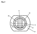
- the end piece 13 serves here as a screw head and is advantageously designed as a square, cf. Fig. 2. But it can also be designed as a square or hexagon.
- the cavity 12 in the carrier means 1 is preferably cylindrical with a cavity diameter D 12 and a cavity depth T 12 rotationally symmetrical with respect to the longitudinal axis AX 1 and penetrates the carrier means 1 from the first component end.
- the cavity diameter D 12 in particular taking into account the inside diameter D 111 of the thread, is designed such that the carrier 1 has at least a wall thickness of 1 mm.
- the membrane 21 of the vibrating element 2 is a flat disk with a predeterminable membrane thickness T 21 .
- the membrane 21 is connected from the first component end at a distance corresponding to the cavity depth T 12 by means of an essentially ring-shaped edge region so as to be rigid with the carrier means 1 in such a way that it seals the cavity 12, in particular pressure-tightly.
- the membrane 21 is designed depending on the material used for the device in its membrane thickness T 21 so that it can perform the mechanical vibrations required to determine the level with a given fatigue strength.
- the vibrating rods 22, 23 arranged on the side of the membrane 21 facing away from the cavity 12 have an oscillating rod distance D 22 at the end and a vibrating rod distance D 21 from one another, the oscillating rod distance D 21 being at most equal to the oscillating rod distance D 22 is.
- the vibrating rods 22, 23 are preferably at a maximum distance from one another if the vibrating element 2 is sufficiently rigid.
- the vibrating rods 22, 23 shaped according to FIG. 2 and arranged on the membrane 21 that they at least in one end of a second component end Section of the component as a straight, substantially parallel mutually extending circular segment cylinders are formed are.
- the oscillating element 2 has, at least in the end section of the component, a cylindrical outer contour with a diameter that is equal to the diameter D 1 ; if necessary, the diameter can also be made smaller than the diameter D 1 .
- a single straight rod-shaped semifinished product having a first and a second rod end for example a round rod with a rod diameter which is at least equal to the end piece diameter D 13, is assumed.
- the final shape of the component is preferably produced from it by machining.
- a first end section of the semifinished product is shaped in such a way that an, especially cylindrical, first attachment A 1 with a largest outer diameter which corresponds to the diameter D 1 and with a length which is less than a rod is, as well as the length of the semi-finished product to a subsequent approach to the a 1, paragraph K arise.
- the shoulder K can also serve as an end edge of the end piece 13 and accordingly the attachment A 1 can only be formed in the first end section after the attachment A 2 has been produced.
- annular groove N 1 of a predeterminable annular groove diameter D N1 and of a predefinable annular groove width B N1 is also pierced within the first end section, which serves to optimize the oscillation ability of the oscillating element 2 to be manufactured.
- the annular groove N 1 is shaped in such a way that the required vibrating rod spacings D 22 , D 21 can be achieved.
- a central longitudinal groove N 2 with a longitudinal groove width that corresponds at the end to the required vibrating rod distance D 22 and on the membrane side to the required vibrating rod distance D 21 is introduced, in particular by milling, that the vibrating rods 22, 23 are completely formed.
- the longitudinal groove N 2 has a longitudinal groove depth T N2 , which corresponds to the difference between the rod length of the semi-finished product and the sum of the cavity depth T 12 and the required membrane thickness T 21 .
- the cavity 12 with a cavity depth T 12 and a cavity diameter D 12 is also produced , for example by milling, in such a way that the cavity 12 practically penetrates into the first end section in such a way that , in particular in the region of the annular groove N 1 , a side of the membrane 21 facing the cavity 12 is formed.
- the cavity diameter D 12 is dimensioned such that a wall with a minimum thickness of 1 mm remains along the cavity 12.
- an annular shoulder is formed on the side facing the cavity 12, which serves to support the electromechanical transducer arrangement to be accommodated in the cavity 12, cf. US-A 54 08 168.
- round bar can be used in the manufacture of the component easily from an equilateral four or a hexagonal rod.
- a such a square or hexagonal rod with an edge spacing which corresponds to a standardized width across flats can be adjusted to the subsequent application of the key edges on the End piece 13 can be dispensed with.
Landscapes
- Physics & Mathematics (AREA)
- Acoustics & Sound (AREA)
- Electromagnetism (AREA)
- Thermal Sciences (AREA)
- Fluid Mechanics (AREA)
- General Physics & Mathematics (AREA)
- Measurement Of Levels Of Liquids Or Fluent Solid Materials (AREA)
- Separation Using Semi-Permeable Membranes (AREA)
- Lining Or Joining Of Plastics Or The Like (AREA)
Applications Claiming Priority (2)
| Application Number | Priority Date | Filing Date | Title |
|---|---|---|---|
| DE1998150316 DE19850316C1 (de) | 1998-11-02 | 1998-11-02 | Einstückiges stabförmiges Bauteil für eine Vorrichtung zur Feststellung eines vorbestimmten Füllstandes in einem Behälter |
| DE19850316 | 1998-11-02 |
Publications (2)
| Publication Number | Publication Date |
|---|---|
| EP1001255A2 true EP1001255A2 (fr) | 2000-05-17 |
| EP1001255A3 EP1001255A3 (fr) | 2002-10-16 |
Family
ID=7886322
Family Applications (1)
| Application Number | Title | Priority Date | Filing Date |
|---|---|---|---|
| EP99120363A Withdrawn EP1001255A3 (fr) | 1998-11-02 | 1999-10-13 | Elément pour un dispositif de détection d'un niveau prédéterminé dans un récipient |
Country Status (2)
| Country | Link |
|---|---|
| EP (1) | EP1001255A3 (fr) |
| DE (1) | DE19850316C1 (fr) |
Family Cites Families (5)
| Publication number | Priority date | Publication date | Assignee | Title |
|---|---|---|---|---|
| DE3044354C2 (de) * | 1980-11-25 | 1983-09-01 | Endress U. Hauser Gmbh U. Co, 7867 Maulburg | Verfahren zur Feststellung des Erreichens eines vorbestimmten Füllstandes in einem Behälter und Vorrichtung zur Durchführung des Verfahrens |
| DE3931453C1 (fr) * | 1989-09-21 | 1991-02-28 | Endress U. Hauser Gmbh U. Co, 7864 Maulburg, De | |
| DE4118793C2 (de) * | 1991-06-07 | 1995-02-09 | Endress Hauser Gmbh Co | Vorrichtung zur Feststellung und/oder Überwachung eines vorbestimmten Füllstandes in einem Behälter |
| EP0762088A3 (fr) * | 1995-09-11 | 1997-11-05 | Georg Fischer Rohrleitungssysteme AG | Procédé et dispositif pour la détection d'un niveau critique pour fluides et matière en vrac |
| DE19621449C2 (de) * | 1996-05-29 | 2000-11-30 | Grieshaber Vega Kg | Vibrationsresonator, Verfahren zum Betreiben eines solchen Vibrationsresonators und Vibrations-Füllstand-Grenzschalter mit einem solchen Vibrationsresonator |
-
1998
- 1998-11-02 DE DE1998150316 patent/DE19850316C1/de not_active Expired - Fee Related
-
1999
- 1999-10-13 EP EP99120363A patent/EP1001255A3/fr not_active Withdrawn
Also Published As
| Publication number | Publication date |
|---|---|
| DE19850316C1 (de) | 2000-05-31 |
| EP1001255A3 (fr) | 2002-10-16 |
Similar Documents
| Publication | Publication Date | Title |
|---|---|---|
| EP2288450B1 (fr) | Sonotrode pour une unité émettrice d'ultrasons | |
| DE69032545T2 (de) | Extrudierter knotenpunkt | |
| EP2315697B1 (fr) | Support pour composant structural d'aéronef pouvant être produit selon un procédé de fusion sélective par laser, utilisation et procédé de production | |
| EP2327535A1 (fr) | Procédé de fabrication d'un objet tridimensionnel | |
| DE202009014956U1 (de) | Ultraschall-Schweißvorrichtung | |
| DE19508632C2 (de) | Verfahren zum Verbinden eines ersten Bauteiles mit einem zweiten Bauteil | |
| DE102018220897A1 (de) | Setzeinheit für eine Stanznietvorrichtung, Stanznietvorrichtung und Verfahren zum Verbinden von Bauteilen | |
| DE2711305A1 (de) | Vorrichtung zur erzeugung von ultraschallwellen | |
| DE4201360A1 (de) | Einrichtung zur fuellstandsmessung | |
| WO2003046390A2 (fr) | Procede pour fixer un insert dans un composant constitue d'une matiere legere | |
| WO2004050294A2 (fr) | Procede de production d'un element constitutif | |
| DE69614322T2 (de) | Vorrichtung an einer Antriebseinheit zur Ultraschallversiegelung | |
| DE202005003067U1 (de) | Sonotrode für die Ultraschall-Verschweißung von thermoplastischen Werkstücken | |
| EP3178583B1 (fr) | Dispositif et procédé de rivetage auto-poinçonnant avec vibration soutenant la force exercée sur le poinçon | |
| DE102010039756A1 (de) | Verfahren zur Herstellung einer Befestigungsvorrichtung | |
| DE19850316C1 (de) | Einstückiges stabförmiges Bauteil für eine Vorrichtung zur Feststellung eines vorbestimmten Füllstandes in einem Behälter | |
| DE3808481C2 (de) | Vorrichtung zur Feststellung eines bestimmten Füllstandes in einem Behälter | |
| EP0659516B2 (fr) | Appareil de soudage par ultrasons | |
| DE202017104190U1 (de) | Ultraschallbearbeitungseinrichtung und radial-resonante Ultraschallsonotrode | |
| DE2829253A1 (de) | Vorrichtung zur verformung einer elastomerschicht fuer einen drehschwingungsdaempfer | |
| EP0064737A2 (fr) | Procédé et dispositif de soudage ultrasonore | |
| EP1421349A1 (fr) | Capteur de mesure de type a vibrations | |
| WO2021121480A2 (fr) | Procédé de réalisation d'un dépôt de métal d'apport et dépôt de métal d'apport | |
| DE2236383A1 (de) | Verfahren zum herstellen von sinterteilen mit innengewinde | |
| EP4392198B1 (fr) | Dispositif de soudage par ultrasons avec un support de sonotrode et une sonotrode fixee a celui-ci |
Legal Events
| Date | Code | Title | Description |
|---|---|---|---|
| PUAI | Public reference made under article 153(3) epc to a published international application that has entered the european phase |
Free format text: ORIGINAL CODE: 0009012 |
|
| AK | Designated contracting states |
Kind code of ref document: A2 Designated state(s): AT BE CH CY DE DK ES FI FR GB GR IE IT LI LU MC NL PT SE |
|
| AX | Request for extension of the european patent |
Free format text: AL;LT;LV;MK;RO;SI |
|
| RAP1 | Party data changed (applicant data changed or rights of an application transferred) |
Owner name: ENDRESS + HAUSER GMBH + CO.KG. |
|
| PUAL | Search report despatched |
Free format text: ORIGINAL CODE: 0009013 |
|
| RIC1 | Information provided on ipc code assigned before grant |
Free format text: 7G 01F 23/296 A, 7G 01F 23/00 B, 7G 01F 23/28 B |
|
| AK | Designated contracting states |
Kind code of ref document: A3 Designated state(s): AT BE CH CY DE DK ES FI FR GB GR IE IT LI LU MC NL PT SE |
|
| AX | Request for extension of the european patent |
Free format text: AL;LT;LV;MK;RO;SI |
|
| 17P | Request for examination filed |
Effective date: 20030409 |
|
| AKX | Designation fees paid |
Designated state(s): DE FR GB IT |
|
| STAA | Information on the status of an ep patent application or granted ep patent |
Free format text: STATUS: THE APPLICATION IS DEEMED TO BE WITHDRAWN |
|
| 18D | Application deemed to be withdrawn |
Effective date: 20080501 |