EP1001292A2 - Übertragungssystem mit polymeren optischen Fasern - Google Patents
Übertragungssystem mit polymeren optischen Fasern Download PDFInfo
- Publication number
- EP1001292A2 EP1001292A2 EP99308674A EP99308674A EP1001292A2 EP 1001292 A2 EP1001292 A2 EP 1001292A2 EP 99308674 A EP99308674 A EP 99308674A EP 99308674 A EP99308674 A EP 99308674A EP 1001292 A2 EP1001292 A2 EP 1001292A2
- Authority
- EP
- European Patent Office
- Prior art keywords
- fiber
- optical
- polymer fiber
- optical signal
- core
- Prior art date
- Legal status (The legal status is an assumption and is not a legal conclusion. Google has not performed a legal analysis and makes no representation as to the accuracy of the status listed.)
- Granted
Links
- 230000003287 optical effect Effects 0.000 title claims abstract description 61
- 229920005594 polymer fiber Polymers 0.000 title claims abstract description 48
- 230000005540 biological transmission Effects 0.000 title claims abstract description 28
- 239000013308 plastic optical fiber Substances 0.000 claims description 13
- 230000008878 coupling Effects 0.000 claims description 6
- 238000010168 coupling process Methods 0.000 claims description 6
- 238000005859 coupling reaction Methods 0.000 claims description 6
- 238000000034 method Methods 0.000 claims description 6
- 239000000835 fiber Substances 0.000 abstract description 43
- 239000006185 dispersion Substances 0.000 abstract description 20
- VYPSYNLAJGMNEJ-UHFFFAOYSA-N Silicium dioxide Chemical compound O=[Si]=O VYPSYNLAJGMNEJ-UHFFFAOYSA-N 0.000 abstract description 6
- 239000000377 silicon dioxide Substances 0.000 abstract description 3
- 238000010420 art technique Methods 0.000 abstract description 2
- 239000013307 optical fiber Substances 0.000 description 7
- 238000010586 diagram Methods 0.000 description 5
- 239000003365 glass fiber Substances 0.000 description 4
- 238000004891 communication Methods 0.000 description 3
- 239000004033 plastic Substances 0.000 description 3
- 229920003023 plastic Polymers 0.000 description 3
- 230000001902 propagating effect Effects 0.000 description 2
- RYGMFSIKBFXOCR-UHFFFAOYSA-N Copper Chemical compound [Cu] RYGMFSIKBFXOCR-UHFFFAOYSA-N 0.000 description 1
- 238000013459 approach Methods 0.000 description 1
- 238000000098 azimuthal photoelectron diffraction Methods 0.000 description 1
- 229910052802 copper Inorganic materials 0.000 description 1
- 239000010949 copper Substances 0.000 description 1
- 238000011161 development Methods 0.000 description 1
- 230000008030 elimination Effects 0.000 description 1
- 238000003379 elimination reaction Methods 0.000 description 1
- 239000011521 glass Substances 0.000 description 1
- 238000002347 injection Methods 0.000 description 1
- 239000007924 injection Substances 0.000 description 1
- 238000005259 measurement Methods 0.000 description 1
- 230000002093 peripheral effect Effects 0.000 description 1
- 229920000642 polymer Polymers 0.000 description 1
- 239000013309 porous organic framework Substances 0.000 description 1
- 230000000644 propagated effect Effects 0.000 description 1
Images
Classifications
-
- G—PHYSICS
- G02—OPTICS
- G02B—OPTICAL ELEMENTS, SYSTEMS OR APPARATUS
- G02B6/00—Light guides; Structural details of arrangements comprising light guides and other optical elements, e.g. couplings
- G02B6/24—Coupling light guides
- G02B6/26—Optical coupling means
- G02B6/268—Optical coupling means for modal dispersion control, e.g. concatenation of light guides having different modal dispersion properties
-
- G—PHYSICS
- G02—OPTICS
- G02B—OPTICAL ELEMENTS, SYSTEMS OR APPARATUS
- G02B6/00—Light guides; Structural details of arrangements comprising light guides and other optical elements, e.g. couplings
- G02B6/24—Coupling light guides
- G02B6/42—Coupling light guides with opto-electronic elements
- G02B6/4201—Packages, e.g. shape, construction, internal or external details
- G02B6/4204—Packages, e.g. shape, construction, internal or external details the coupling comprising intermediate optical elements, e.g. lenses, holograms
- G02B6/4206—Optical features
Definitions
- This invention relates to a method and apparatus for increasing the capacity of lightwave transmission systems and, more particularly, to a method and apparatus for reducing the complexity and costs of polymer optical fiber based lightwave systems.
- a single-mode fiber 104 is connected through a coupler 105 to the multi-mode fiber 107.
- the coupler 105 is used to selectively propagate only higher-order modes over the multi-mode fiber 107.
- Other arrangements splice the single-mode fiber 104 to the multi-mode fiber 107 to facilitate the launching of only the lower-order modes over the multi-mode fiber 107.
- polymer (plastic) optical fiber (hereinafter also referred to as POF) has been developed for use in optical transmission systems. Because of its large diameter polymer fiber also promotes multi-mode transmission. However, because of its relatively high transmission loss characteristics and its less-desirable transmission wavelength, about 650 nm, polymer fiber has typically only been used in short distance applications. Recently, POF have also been proposed for use in optical transmission systems. An illustrative system is described in the article by H. Imai entitled “APPLICATIONS OF PERFLUORINATED POLYMER FIBERS TO OPTICAL TRANSMISSION,” published on Sep. 22, 1997 in Proceedings of Seventh International Plastics Optical Fiber Conference, pp. 29-30.
- Figure 1 is a simplified representation of the PF fiber based optical system described in the Imai article. Again a single-mode fiber 104 is connected in front of the POF 107 and is used to selectively propagate only lower-order mode transmission over the multi-mode POF.
- some polymer fiber exhibits a delay characteristic that has a broad low dispersion region or "sweet-spot" where propagation delay of a spatially restricted optical pulse remains relatively constant as a function of injection position. This sweet-spot is centered around the center axis of the fiber core.
- optical pulse dispersion can be significantly reduced without the need for using the prior art technique of using a single mode fiber spliced in series with the POF to reduce dispersion.
- a polymer fiber based optical transmission system using this arrangement exhibits relaxed alignment tolerances between the optical source and polymer fiber, while reducing dispersion and increasing bandwidth-length product.
- our inventive optical transmission apparatus comprises an optical signal restriction device for coupling a received optical signal to a predefined central region of a core region of a polymer fiber which has an approximately flat delay characteristic throughout that central region.
- an optical signal is transmitted over an polymer fiber by focussing the optical signal to a spot of predefined diameter and coupling the optical signal spot to a predetermined central region of a core region of the polymer fiber which exhibits an approximately flat delay characteristic throughout the central region.
- each item or block of each figure has a reference designation associated therewith, the first number of which refers to the figure in which that item is first described (e.g., 101 is first described in FIG. 1).
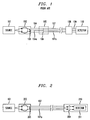
- Fig. 1 shows an illustrative block diagram of a prior art optical transmission system that utilizes a polymer fiber 107.
- the polymer fiber with a graded-index has been shown to exhibit low wavelength loss at the desirable laser wavelength of 1.3 ⁇ m.
- the polymer fiber 107 may be of the same type as used in our Fig. 2 system, namely, graded-index perfluorinated plastic optical fiber.
- a modulated optical source 101 such as a Fabry-Perot laser diode
- a launch restriction device 102 to a single-mode glass (SM) optical fiber 104.
- the optical source 101 is a 1.3 ⁇ m Fabry-Perot laser diode and that the launch restriction device 102 is a ball lens.
- the SM fiber 104 is coupled or spliced 105 to the polymer fiber 107.
- the single-mode fiber 104 facilitates selective launching of lower-order modes to the polymer fiber 107.
- the output of the polymer fiber 107 is coupled via a lens 108 to another SM fiber section 109.
- the single-mode fiber 109 filters out any undesirable higher-order modes from the desired lower-order modes.
- a detector 108 receives and demodulates the lower-order mode based optical signal received over from SM fiber 109.
- the lens 108 may be a hemispherical-ended lens and the detector 108 may be an avalanche photodiode (APD).
- APD avalanche photodiode
- the laser signal from source 101 is focussed by ball lens 102 to a predefined diameter spot 103 which is less than or about the same size as the core diameter 104a of the SM fiber 104. Since the SM fiber 104 and the polymer fiber 107 have the same outside diameter, it is relatively easy to splice them together so that the core 104a of SM fiber 104 aligns with the center of core 107a of polymer fiber 107. Typically, the diameter of core 104a of the SM fiber 104 is about 50 ⁇ m and the core 107a of the polymer fiber 107 is about 120 ⁇ m to 1mm. Disadvantageously, there may be a significant splicing or coupling loss, of about 1 dB, between the SM fiber 104 and the polymer fiber 107.
- Multi-mode fibers such as polymer fiber 107, suffer from a phenomenon known as "modal dispersion.”
- This modal dispersion is caused when the input optical signal pulse from the source excites multiple modes of the polymer fiber 107. These multiple modes travel at different velocities in polymer fiber 107 and cause the pulse to disperse or spread as it propagates down the fiber. This spreading of the pulse imposes a limit as to how close adjacent pulses can be sent over the polymer fiber and, hence, reduces the maximum data rate that can be sent over the polymer fiber. Since pulse dispersion increases with distance a "bandwidth-distance" product is used to determine if a particular transmission system is suitable for a particular application.
- a SM fiber 104 confines the optical signal to a small area, it may be used to facilitate the launch of lower-order modes into the polymer fiber 107.
- the term "lower-order” modes means that most of the optical energy is localized in the central region of the fiber core.
- higher-order modes means that most of the optical energy is outside the central region of the fiber core.
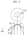
- FIG. 3 With reference to top of Fig. 3, there is shown a cross-section of a core region 304 of a typical polymer fiber.
- the lower part of Fig. 3 shows the typical variation of the delay characteristic 301, across the core region 304, that is exhibited by polymer fibers.
- all graded index fibers have a nominally parabolic index profile, but their delay characteristics are not typically parabolic. Delay characteristics depend on non-idealities of the profile and on mode coupling. As shown, the delay changes as one moves radially outward from the center of core 304. Because the delay greatly varies across the core region 304 significant pulse dispersion will result between the lower-order modes that travel in the central region 303 and the higher-order modes that travel outside the central region 303.
- the polymer fiber when operated at an optical wavelength of 1.3 ⁇ , exhibits a delay characteristic 302 that has a broad and relatively flat region or "sweet-spot" 303.
- This sweet-spot also referred to as a low-dispersion region
- This sweet-spot is a region centered around the longitudinal axis of the fiber core 304.
- the "diameter" of the low-dispersion region 303 is, typically, a significant part of the diameter (e.g., about half) of the core 304.
- FIG. 2 there is shown, in accordance with the present invention, an illustrative block diagram of our improved POF fiber based optical transmission system.
- the system includes all of the elements from Fig. 1 except that no SM fiber segment 104 is utilized.
- the optical signal source 101 is coupled via lens 202 to the sweet-spot 203 of core 107a of polymer fiber 107. Since the sweet-spot for a polymer fiber, with a core diameter of 250 ⁇ m, is on the order of 120 ⁇ m, it is significantly greater that the 50 ⁇ m core diameter of the SM fiber 104.
- the lens 202 can have a reduced alignment and focussing requirement with the PF fiber 107.
- the sweet-spot of 120 ⁇ m is over half the core diameter, transmission capacity can remain high even if the optical signal (about 50 ⁇ m ) is somewhat off center.
- other types of focussing devices 202 may be used, such as multiple lens systems.
- an avalanche photodiode detector (APD) with a built in lens may be used as the lens 209 and detector 211 of Fig. 2.
- APDs have diameters on the order of the diameter of the sweet-spot, it may be possible to eliminate the lens 209 and directly abut the APD to the sweet-spot i.e., at the center of core 304.
- optical source 101 could also be a Light emitting diode (LED) rather than a Faby-Perot laser diode.
- the launch restriction device 102 can be other than a ball lens.
- the ball lens 102 may be mounted or packaged as part of the laser diode 101.
Landscapes
- Physics & Mathematics (AREA)
- General Physics & Mathematics (AREA)
- Optics & Photonics (AREA)
- Chemical & Material Sciences (AREA)
- Dispersion Chemistry (AREA)
- Optical Couplings Of Light Guides (AREA)
- Optical Communication System (AREA)
- Optical Fibers, Optical Fiber Cores, And Optical Fiber Bundles (AREA)
- Light Guides In General And Applications Therefor (AREA)
Applications Claiming Priority (2)
| Application Number | Priority Date | Filing Date | Title |
|---|---|---|---|
| US09/190,504 US6157757A (en) | 1998-11-12 | 1998-11-12 | Polymer fiber optical transmission system |
| US190504 | 1998-11-12 |
Publications (3)
| Publication Number | Publication Date |
|---|---|
| EP1001292A2 true EP1001292A2 (de) | 2000-05-17 |
| EP1001292A3 EP1001292A3 (de) | 2002-06-05 |
| EP1001292B1 EP1001292B1 (de) | 2005-08-24 |
Family
ID=22701619
Family Applications (1)
| Application Number | Title | Priority Date | Filing Date |
|---|---|---|---|
| EP99308674A Expired - Lifetime EP1001292B1 (de) | 1998-11-12 | 1999-11-02 | Übertragungssystem mit polymeren optischen Fasern |
Country Status (6)
| Country | Link |
|---|---|
| US (1) | US6157757A (de) |
| EP (1) | EP1001292B1 (de) |
| JP (1) | JP3681938B2 (de) |
| AU (1) | AU5830499A (de) |
| CA (1) | CA2282971A1 (de) |
| DE (1) | DE69926853T2 (de) |
Cited By (4)
| Publication number | Priority date | Publication date | Assignee | Title |
|---|---|---|---|---|
| WO2002001261A1 (en) * | 2000-06-27 | 2002-01-03 | Mitsubishi Rayon Co., Ltd. | Plastic optical fiber, optical fiber cable and optical transmission device |
| EP1211538A3 (de) * | 2000-11-30 | 2002-09-04 | Matsushita Electric Industrial Co., Ltd. | Optisches Übertragungssystem |
| GB2399963A (en) * | 2003-02-05 | 2004-09-29 | Zinwave Ltd | Multiple transverse mode laser transmitters in radio over fibre communication system |
| CN113347105A (zh) * | 2021-05-14 | 2021-09-03 | 翁德喜 | 一种高聚物光纤路由器 |
Families Citing this family (11)
| Publication number | Priority date | Publication date | Assignee | Title |
|---|---|---|---|---|
| US7039322B1 (en) * | 1998-12-24 | 2006-05-02 | Mitsubishi Rayon Co., Ltd. | Optical communication apparatus |
| US6510265B1 (en) * | 1999-04-21 | 2003-01-21 | Lucent Technologies Inc. | High-speed multi mode fiber optic link |
| US6917749B2 (en) | 2001-11-07 | 2005-07-12 | Photon-X, Llc | Polymer optical waveguides on polymer substrates |
| TW548439B (en) * | 2002-01-15 | 2003-08-21 | Delta Electronics Inc | Manufacturing method of fiber collimator |
| US7590319B2 (en) * | 2004-02-06 | 2009-09-15 | Fujifilm Corporation | Preform for plastic optical material, production method thereof, optical coupling method of plastic optical fiber and connector used for optical coupling |
| US7502533B2 (en) * | 2006-04-25 | 2009-03-10 | Intel Corporation | Mechanism for conditioning launched beams from an optical transmitter |
| US20110075976A1 (en) * | 2009-09-30 | 2011-03-31 | James Scott Sutherland | Substrates and grippers for optical fiber alignment with optical element(s) and related methods |
| US8477298B2 (en) * | 2009-09-30 | 2013-07-02 | Corning Incorporated | Angle-cleaved optical fibers and methods of making and using same |
| US8295671B2 (en) * | 2009-10-15 | 2012-10-23 | Corning Incorporated | Coated optical fibers and related apparatuses, links, and methods for providing optical attenuation |
| US9711930B2 (en) | 2015-12-01 | 2017-07-18 | Seagate Technology Llc | Optical signal waveguide dispersion filter |
| US20240195503A1 (en) * | 2021-04-07 | 2024-06-13 | Yasuhiro Koike | Optical transmission system, optical transmission path, and photoelectric composite cable |
Family Cites Families (6)
| Publication number | Priority date | Publication date | Assignee | Title |
|---|---|---|---|---|
| CA1247415A (en) * | 1984-03-02 | 1988-12-28 | Isao Sasaki | Light-transmitting fiber |
| EP0183853B1 (de) * | 1984-05-30 | 1993-08-11 | Mitsubishi Rayon Co., Ltd. | Kunststoffaser mit optischen übertragungseigenschaften |
| DE3617799A1 (de) * | 1986-05-27 | 1987-12-03 | Standard Elektrik Lorenz Ag | Optischer sender |
| JPS63282705A (ja) * | 1987-05-15 | 1988-11-18 | Idemitsu Petrochem Co Ltd | プラスチック光伝送性繊維 |
| EP0336156A1 (de) * | 1988-03-31 | 1989-10-11 | Siemens Aktiengesellschaft | Hermetisch dichte Lichtleitfaser-Linsen-Anordnung, insbesondere für optoelektronische Module, und Verfahren zu ihrer Herstellung |
| US5416862A (en) * | 1993-04-07 | 1995-05-16 | At&T Corp. | Lightwave transmission system using selected optical modes |
-
1998
- 1998-11-12 US US09/190,504 patent/US6157757A/en not_active Expired - Lifetime
-
1999
- 1999-09-22 CA CA002282971A patent/CA2282971A1/en not_active Abandoned
- 1999-11-02 DE DE69926853T patent/DE69926853T2/de not_active Expired - Lifetime
- 1999-11-02 EP EP99308674A patent/EP1001292B1/de not_active Expired - Lifetime
- 1999-11-05 AU AU58304/99A patent/AU5830499A/en not_active Abandoned
- 1999-11-12 JP JP32187799A patent/JP3681938B2/ja not_active Expired - Lifetime
Cited By (7)
| Publication number | Priority date | Publication date | Assignee | Title |
|---|---|---|---|---|
| WO2002001261A1 (en) * | 2000-06-27 | 2002-01-03 | Mitsubishi Rayon Co., Ltd. | Plastic optical fiber, optical fiber cable and optical transmission device |
| US6606441B2 (en) | 2000-06-27 | 2003-08-12 | Mitsubishi Rayon Co., Ltd. | Plastic optical fiber, optical fiber cable and optical transmission device |
| EP1211538A3 (de) * | 2000-11-30 | 2002-09-04 | Matsushita Electric Industrial Co., Ltd. | Optisches Übertragungssystem |
| US7212745B2 (en) | 2000-11-30 | 2007-05-01 | Matsushita Electric Industrial Co., Ltd. | Optical transmission system |
| GB2399963A (en) * | 2003-02-05 | 2004-09-29 | Zinwave Ltd | Multiple transverse mode laser transmitters in radio over fibre communication system |
| GB2399963B (en) * | 2003-02-05 | 2006-04-05 | Zinwave Ltd | Multimode fibre optical communication system |
| CN113347105A (zh) * | 2021-05-14 | 2021-09-03 | 翁德喜 | 一种高聚物光纤路由器 |
Also Published As
| Publication number | Publication date |
|---|---|
| DE69926853T2 (de) | 2006-06-08 |
| EP1001292A3 (de) | 2002-06-05 |
| AU5830499A (en) | 2000-05-18 |
| EP1001292B1 (de) | 2005-08-24 |
| US6157757A (en) | 2000-12-05 |
| DE69926853D1 (de) | 2005-09-29 |
| JP3681938B2 (ja) | 2005-08-10 |
| CA2282971A1 (en) | 2000-05-12 |
| JP2000147294A (ja) | 2000-05-26 |
Similar Documents
| Publication | Publication Date | Title |
|---|---|---|
| US6185346B1 (en) | Propagation in lowest order modes of multimode graded index fiber, resulting in: very low transmission loss, low modal noise, high data security, and high data rate capabilities | |
| US6157757A (en) | Polymer fiber optical transmission system | |
| US5416862A (en) | Lightwave transmission system using selected optical modes | |
| Van den Boom et al. | High-capacity transmission over polymer optical fiber | |
| US20040033039A1 (en) | Network for distributing signals to a plurality of user equipment | |
| US6415076B1 (en) | Mode conditioning patch for facilitating signal transmission from single mode optical fiber to multimode optical fiber | |
| WO2006083938A2 (en) | Fiber stub for cladding mode coupling reduction | |
| JPS6214609A (ja) | 光フアイバ分配ネツトワ−ク | |
| US4955014A (en) | Broadband optical communication system, particularly in the subscriber area | |
| US9991961B2 (en) | Multimode fiber for modulatable source | |
| US20020164115A1 (en) | Optical fiber communication system, communications apparatus and optical transceiver | |
| US20030031408A1 (en) | Mode sensitive filter and optical transmitter/receiver | |
| US6476951B1 (en) | Use of mode coupled optical fiber in communications systems | |
| Jacobs et al. | Communications: Optical transmission of voice and data: Bandwidth and noise immunity are up; size, weight, and costs are down | |
| EP1938130B1 (de) | Hohe bitrate über mehrmoden-fasern | |
| Wells | Crosstalk in a bidirectional optical fiber | |
| Hollis et al. | Fiber optics for CATV in perspective | |
| Elgamal et al. | Bit rate maximizing by optimizing repeater spacing product for optical communication systems | |
| JP3830376B2 (ja) | 送信ユニット | |
| Stach | High-performance low-cost optical link at 850 nm with optimized standard singlemode fiber and high-speed singlemode VCSEL | |
| JP2710407B2 (ja) | 光パルス送信方法 | |
| KR100698601B1 (ko) | 광선로 거리 측정 장치 | |
| KR20050033188A (ko) | 모드변환기 및 이를 이용한 모드 조절 패치코드와 연결기 | |
| Li | The future of optical fibers for data communications | |
| Chen et al. | Studies of Polymer Optical Fibers |
Legal Events
| Date | Code | Title | Description |
|---|---|---|---|
| PUAI | Public reference made under article 153(3) epc to a published international application that has entered the european phase |
Free format text: ORIGINAL CODE: 0009012 |
|
| AK | Designated contracting states |
Kind code of ref document: A2 Designated state(s): AT BE CH CY DE DK ES FI FR GB GR IE IT LI LU MC NL PT SE |
|
| AX | Request for extension of the european patent |
Free format text: AL;LT;LV;MK;RO;SI |
|
| RIN1 | Information on inventor provided before grant (corrected) |
Inventor name: WHITE, WHITNEY Inventor name: GIARETTA, GIORGIO |
|
| PUAL | Search report despatched |
Free format text: ORIGINAL CODE: 0009013 |
|
| AK | Designated contracting states |
Kind code of ref document: A3 Designated state(s): AT BE CH CY DE DK ES FI FR GB GR IE IT LI LU MC NL PT SE |
|
| AX | Request for extension of the european patent |
Free format text: AL;LT;LV;MK;RO;SI |
|
| RIC1 | Information provided on ipc code assigned before grant |
Free format text: 7G 02B 6/42 A, 7H 04B 10/18 B, 7G 02B 6/16 B, 7G 02B 6/26 B |
|
| 17P | Request for examination filed |
Effective date: 20021114 |
|
| AKX | Designation fees paid |
Designated state(s): DE FR GB |
|
| 17Q | First examination report despatched |
Effective date: 20031013 |
|
| RAP1 | Party data changed (applicant data changed or rights of an application transferred) |
Owner name: CHROMIS FIBEROPTICS, LLC |
|
| GRAP | Despatch of communication of intention to grant a patent |
Free format text: ORIGINAL CODE: EPIDOSNIGR1 |
|
| GRAS | Grant fee paid |
Free format text: ORIGINAL CODE: EPIDOSNIGR3 |
|
| GRAA | (expected) grant |
Free format text: ORIGINAL CODE: 0009210 |
|
| AK | Designated contracting states |
Kind code of ref document: B1 Designated state(s): DE FR GB |
|
| REG | Reference to a national code |
Ref country code: GB Ref legal event code: FG4D |
|
| REF | Corresponds to: |
Ref document number: 69926853 Country of ref document: DE Date of ref document: 20050929 Kind code of ref document: P |
|
| ET | Fr: translation filed | ||
| PLBE | No opposition filed within time limit |
Free format text: ORIGINAL CODE: 0009261 |
|
| STAA | Information on the status of an ep patent application or granted ep patent |
Free format text: STATUS: NO OPPOSITION FILED WITHIN TIME LIMIT |
|
| 26N | No opposition filed |
Effective date: 20060526 |
|
| REG | Reference to a national code |
Ref country code: FR Ref legal event code: PLFP Year of fee payment: 17 |
|
| REG | Reference to a national code |
Ref country code: FR Ref legal event code: PLFP Year of fee payment: 18 |
|
| REG | Reference to a national code |
Ref country code: FR Ref legal event code: PLFP Year of fee payment: 19 |
|
| PGFP | Annual fee paid to national office [announced via postgrant information from national office to epo] |
Ref country code: DE Payment date: 20181128 Year of fee payment: 20 |
|
| PGFP | Annual fee paid to national office [announced via postgrant information from national office to epo] |
Ref country code: GB Payment date: 20181127 Year of fee payment: 20 Ref country code: FR Payment date: 20181127 Year of fee payment: 20 |
|
| REG | Reference to a national code |
Ref country code: DE Ref legal event code: R071 Ref document number: 69926853 Country of ref document: DE |
|
| REG | Reference to a national code |
Ref country code: GB Ref legal event code: PE20 Expiry date: 20191101 |
|
| PG25 | Lapsed in a contracting state [announced via postgrant information from national office to epo] |
Ref country code: GB Free format text: LAPSE BECAUSE OF EXPIRATION OF PROTECTION Effective date: 20191101 |