EP1001302A1 - Federscharnier für Brillen - Google Patents
Federscharnier für Brillen Download PDFInfo
- Publication number
- EP1001302A1 EP1001302A1 EP99308931A EP99308931A EP1001302A1 EP 1001302 A1 EP1001302 A1 EP 1001302A1 EP 99308931 A EP99308931 A EP 99308931A EP 99308931 A EP99308931 A EP 99308931A EP 1001302 A1 EP1001302 A1 EP 1001302A1
- Authority
- EP
- European Patent Office
- Prior art keywords
- temple
- spring
- state
- eyeglasses
- armor
- Prior art date
- Legal status (The legal status is an assumption and is not a legal conclusion. Google has not performed a legal analysis and makes no representation as to the accuracy of the status listed.)
- Granted
Links
- 230000009471 action Effects 0.000 description 28
- 238000010276 construction Methods 0.000 description 13
- 230000009466 transformation Effects 0.000 description 12
- NJPPVKZQTLUDBO-UHFFFAOYSA-N novaluron Chemical compound C1=C(Cl)C(OC(F)(F)C(OC(F)(F)F)F)=CC=C1NC(=O)NC(=O)C1=C(F)C=CC=C1F NJPPVKZQTLUDBO-UHFFFAOYSA-N 0.000 description 10
- 230000002123 temporal effect Effects 0.000 description 10
- 230000008901 benefit Effects 0.000 description 8
- 230000000694 effects Effects 0.000 description 6
- 238000003780 insertion Methods 0.000 description 6
- 230000037431 insertion Effects 0.000 description 6
- 238000004519 manufacturing process Methods 0.000 description 6
- 238000009434 installation Methods 0.000 description 4
- 229910001040 Beta-titanium Inorganic materials 0.000 description 3
- 206010016275 Fear Diseases 0.000 description 3
- 230000006872 improvement Effects 0.000 description 3
- 239000000463 material Substances 0.000 description 3
- 238000011328 necessary treatment Methods 0.000 description 3
- 230000002093 peripheral effect Effects 0.000 description 3
- 238000007747 plating Methods 0.000 description 3
- 230000000007 visual effect Effects 0.000 description 3
- 230000035939 shock Effects 0.000 description 2
- 238000005452 bending Methods 0.000 description 1
- 238000005219 brazing Methods 0.000 description 1
- 230000006835 compression Effects 0.000 description 1
- 238000007906 compression Methods 0.000 description 1
- 230000003247 decreasing effect Effects 0.000 description 1
- 238000004090 dissolution Methods 0.000 description 1
- 230000004048 modification Effects 0.000 description 1
- 238000012986 modification Methods 0.000 description 1
- 230000002265 prevention Effects 0.000 description 1
- 230000009467 reduction Effects 0.000 description 1
- 238000009751 slip forming Methods 0.000 description 1
- 239000002699 waste material Substances 0.000 description 1
Images

















Classifications
-
- G—PHYSICS
- G02—OPTICS
- G02C—SPECTACLES; SUNGLASSES OR GOGGLES INSOFAR AS THEY HAVE THE SAME FEATURES AS SPECTACLES; CONTACT LENSES
- G02C5/00—Constructions of non-optical parts
- G02C5/02—Bridges; Browbars; Intermediate bars
- G02C5/10—Intermediate bars or bars between bridge and side-members
-
- G—PHYSICS
- G02—OPTICS
- G02C—SPECTACLES; SUNGLASSES OR GOGGLES INSOFAR AS THEY HAVE THE SAME FEATURES AS SPECTACLES; CONTACT LENSES
- G02C5/00—Constructions of non-optical parts
- G02C5/22—Hinges
- G02C5/2218—Resilient hinges
- G02C5/2254—Resilient hinges comprising elastic means other than coil spring
-
- G—PHYSICS
- G02—OPTICS
- G02C—SPECTACLES; SUNGLASSES OR GOGGLES INSOFAR AS THEY HAVE THE SAME FEATURES AS SPECTACLES; CONTACT LENSES
- G02C2200/00—Generic mechanical aspects applicable to one or more of the groups G02C1/00 - G02C5/00 and G02C9/00 - G02C13/00 and their subgroups
- G02C2200/22—Leaf spring
-
- G—PHYSICS
- G02—OPTICS
- G02C—SPECTACLES; SUNGLASSES OR GOGGLES INSOFAR AS THEY HAVE THE SAME FEATURES AS SPECTACLES; CONTACT LENSES
- G02C2200/00—Generic mechanical aspects applicable to one or more of the groups G02C1/00 - G02C5/00 and G02C9/00 - G02C13/00 and their subgroups
- G02C2200/32—Oblong hole
Definitions
- This invention relates to a spring hinge for eyeglasses which enables a temple to fit onto a temporal and to open and close with a moderate resistance.
- the spring hinge had a structure in which an armor-side hinge member (c) conmprising a joint member (b) projectingly mounted to a pedestal (a) and a temple-side hinge member (e) with a spring coil (d) inside and a screw (f) by which the armor-side hinge member (c) and the temple-side hinge member (e) were pivotally connected to each other so that they could be opened and closed.
- an armor-side hinge member (c) conmprising a joint member (b) projectingly mounted to a pedestal (a) and a temple-side hinge member (e) with a spring coil (d) inside and a screw (f) by which the armor-side hinge member (c) and the temple-side hinge member (e) were pivotally connected to each other so that they could be opened and closed.
- the temple-side hinge member (e) was so structured that a sliding body (h) of a sliding member (j) comprising a joint member (i) projectingly mounted to the tip of the sliding body (h) was contained in a case (g) which was formed long and narrow in a direction of length of a temple and one end of the case is kept open.
- an engaging pin (u) was mounted to walls (k,k) facing to each other, and the coil spring (d) was mounted between the engaging pin (u) and a spring support member (m) mounted at the rear end of the above mentioned sliding body (h), so that a certain length of the sliding body (h) could be drawn from the case (g) against elasticity compression of the coil spring (d).
- the inner surface of the rip of the temple (n) was cut off at a part facing to an outside opening of the case (g) to form a concavity (o)
- a periphery (p) of the opening of the case (g) was put into contact with a periphery (q) of the concavity (o)
- the joint thereof was brazed.
- the concavity (o) was formed with an intention to reduce the thickness of the case (g) as much as possible by jointly using a containable space (r) of the case (g) and the concavity (o).
- the conventional spring hinge was a sliding-type spring hinge in which the armor-side hinge member (c) and the temple-side hinge member (e) were connected to each other by a screw (f), and a sliding body (h) was constructed to be slidable by receiving momentum of the coil spring (d), however, there were the following problems.
- the plate spring hinge has a structure in which an armor-side joint member (B) mounted to an armor (A) and a temple-side joint member (D) mounted to a temple (C) , are combined with each other as shown in Fig. 38.
- the armor-side joint member (B) has a joint portion (F) which projects at a position apart from an inner surface (E) of the armor, and an oblong pin hole (G) is provided at the joint portioin (F).
- the above mentioned temple-side joint member (D) consists of a box-shaped support pedestal (H) projectingly mounted on the inner surface of the temple, and a plate spring (I) is projectingly mounted forward while the plate spring (I) is fixed at a rear end of the box-shaped support pedestal (H).
- a front end (J) of the plate spring (I) is in contact with an outer surface (K) of the joint portion (F)
- the temple (C) presents an unfolded state, in which the joint members (B) and (D) are pivotablly mounted to each other with a screw pin (L) which pierces the pinhole of the temple-side joint member (D) and the oblong pinhole (G).
- the former spring hhinge using a coil spring (d) was a slide-type spring hinge in which the armor-side hinge member (c) and the temple-side hinge member (e) were connected to each other by a screw (f), and a sliding body (h) was constructed to be slidable by receiving momentum of the coil spring (d), however, there were the following problems. 1 ⁇
- the above mentioned spring hinge was so constructed that the sliding body (h) equipped with the coil spring (d) was placed in the case (g). Therefore, even if the concavity (o) was provided as shown in Fig. 37, the case (g) in a box shape structurally occupying a certain space considerably projected at the inside of the temple (n), which was conspicuous, wherefore there was a problem of bad appearance.
- slenderly structured eyeglasses are highly regarded such as eyeglasses with slender temples, rimless eyeglasses so-called "two-point", in which temples are directly connected to lenses, rimless eyeglasses in which lenses are supported with cord which is connected to curving frames.
- two-point in which temples are directly connected to lenses
- rimless eyeglasses in which lenses are supported with cord which is connected to curving frames.
- the conventional spring hinge was so constructed that the armor-side member (c) and the temple-side hinge member (e) were connected to each other by the screw (f) so that the both members could be opened and closed.
- rotational action worked on the screw (f) while the eyeglasses are in use, by which the screw might loosen and the temple (n) might fall by its self-weight without intension of a wearer of the eyeglasses.
- the latter spring hinge provided with the plate spring (J) also had problems as mentioned below. 1 ⁇ Since the plate spring (I) is flexiblly transformed each time the temple is folded and unfolded as shown in Fig. 40, there was a problem that the spring action of the plate spring was easy to be deteriorated.
- the temple-side joint member (D) is constituted using the box-shaped support pedestal (H) which substantially projects at the inside (P) of the temple taking room for the flexible transformation into consideration.
- An object of this invention is to solve the follwing problems and to enable a temple to fit onto a temporal while the eyeglasses are in use by utilizing a required momentum action of a spring member.
- the object of this invention relation to the former spring hinge provided with a coil spring is: 1 ⁇ to form the whole spring hinge compact to present a good appearance, 2 ⁇ to have the momentum of the spring constituting the spring hinge effectively function for improving fitness of the temple onto the temporal and for prevention of unprepared fall of the temple, and of damages to the lense rim, the lense, and the modern, 3 ⁇ to provide a spring hinge which can be mounted even to a slender temple while maintaining a good appearance and at the same time which can provide an appropriate momentum action according to a desing of the temple, by which to improve fashion of the eyeglasses with slender temples and to improve function of a slender temple, i. e.
- a spring hinge for eyeglasses in which upper and lower connecting members are provided at a temple side to face to each other leaving a predetermined distance in up and down directions, an intermediate connecting member provided at a side of an armor to be inserted between the upper and lower connecting members, and a pivot shaft for pivotably connecting the upper and lower connecting members and the intermediate connecting member, so that a temple may be folded from a predetermined state of open, comprises a spring member provided on the side of the temple; said spring member having a flexible press portion for flexibly pressing, from the inside of the armor, an arc periphery of the intermediate connecting member which arc periphery is formed by a center of the pivot shaft, thereby the temple in the predetermined opened state may be folded and opened while keeping the flexible pressing state.
- folding and opening of the temple in a state that the flexible press portion contacts the arc periphery of the intermediate member, is carried out not to make felxible deformation of the spring member.
- a rear portion of the armor presses the spring member from its outerside to its inside so as to flexibly deform or transform the spring member when the temple in a predetermined open state is opened outwardly.
- the spring member is formed to be a line having flexibility and its front portion is formed to be the flexible press portion and its rear end portion or a portion of the spring member adjacent its rear end portion is attached on the side of the temple.
- a portion of the flexible press portion, which contacts the arc periphery of the intermediate connecting member is formed to have a curved face which contacts the arc periphery with contact of face to face.
- Another aspect of the spring hinge according to this invention is as follows.
- the spring hinge for eyeglasses in which upper and lower connecting members are provided at an armor-side to face to each other leaving a predetermined distance in up and down directions, an intermediate connecting member provided at a side of an armor to be inserted between the upper and lower connecting members, and a pivot shaft for pivotably connecting the upper and lower connecting members and the the intermediate connecting member, so that a temple may be folded from a predetermined state of open, comprises a spring member provided on the side of the armor; said spring member having a flexible press portion for flexibly pressing, from the inside of the temple, an arc periphery of the intermediate connecting member which arc periphery is formed by a center of the pivot shaft, thereby the temple in the predetermined opened state may be folded and opened while keeping the flexible pressing state, and folding and opening of the temple, in a state that the flexible press portion contacts the arc periphery of the intermediate member, is carried out not to make felxible deformation or transformation of the spring member, and also a rear portion of the armor presses the spring member from its outer
- the spring member is formed to be a line having flexibility and its front portion is formed to be the flexible press portion and its rear end portion or a portion of the spring member adjacent its rear end portion is attached on the side of the temple.
- a portion of the flexible press portion, which contacts the arc periphery of the intermediate connecting member is formed to have a curved face which contacts the arc periphery with contact of face to face.
- the spring hinge according to the present invention has the following effects as well as the advantages that the temple fits onto a temporal while the eyeglasses are in use just like the conventional spring hinge, and in case an object hits the eyeglasses while they are in use, the temple are flexiblly expanded and opened to avoid the lenses from breaking.
- the spring hinge according to this invention is different from the conventional slide-type spring hinge in a sense that the former utilizes flexibility transformation only, wherefore the structure can be simple and compact. Further, improvement in manufacturing efficiency and reduction in manufacturing cost can also be expected.
- the spring hinge can be formed so compact that the spring hinge can be attached well even to a slender temple in terms of appearance, and by fixing a requirement momentum by changing a diameter of a spring, momentum action which is appropriate for a type of a temple, can be obtained. Because of the above mentioned reasons, the flexible expansion and opending force of a temple does not work too much on a lense even in a slender temple.
- this invention is particularly effective to frames of eyeglasses with slender temples, and can attain improvement in function as well as in fashion.
- the above mentioned spring constituting the spring hinge according to this invention has a structure in which a flexiblly press portion of the spring member, flexiblly presses an arc periphery of the above mentioned intermediate connecting member, the temples in an unfolded state expanding backwards can be opened and closed with a moderate resistance while maintaining the above mentioned flexiblly pressing state.
- the intermediate connecting member provides an arc periphery which is formed about a pivot shaft and it is so composed that the flexible press portion of the spring member flexiblly presses the arc periphery always and that folding and unfolding of the tmple while the flexible press portion contacts the arc periphery under pressure, it becomes possible to carry out folding and unfolding of the temple without causing unnecessary flexible transformation of the spring member.
- the spring member in the invention claimed in claim 2 is formed in a line, the peculiar effects of which is the same as the invention claimed in claim 1.
- the spring hinge can be made compact to present a good appearance and to fit well to the slender temple.
- the spring hinge related to the invention when the intermediate connecting member is inserted between the upper and lower connecting members while fitting each of the holes of these members coaxially, and a pivot axis is pierce through these holes to connect the three connecting members, it can be prevented that the flexible press portion and the arc periphery of the intermediate connecting member slip one another, by which insertion of the intermediate connecting member between the upper and lower connecting members and the connection of the three connecting members by a pivot shaft can be simplified. Further, because of the contact by surface with the curving surface, wear of the intermediate connecting member and the spring member can be decreased in comparison to the state of contact at a point, wherefore there is an advantage that durability of the spring hinge can be improved substantially.
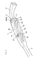
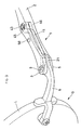
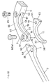
- a spring hinge 1 is utilized for comprising rimless eyglasses G , in which a temple 2 is directly connected to a lens L , and so it is called "two point". Its whole construction will be described with reference to Figs. 1 to 6.
- an intermediate connecting member 7 is inserted between upper and lower connecting members 3 and 5, which are provided in a state of facing each other leaving a predetermined distance in up and down directions.
- the intermediate connecting member 7 is, for example, provided at a rear portion of an armor 6 which is bent in the form of an L-letter.
- the connecting members 3, 5 and 7 are connected to one another by a pivot shaft 9 (Fig.
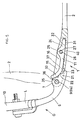
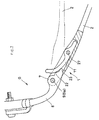
- the temple 2 is so composed to be foldable so as to overlap an eyeglass front 10 as shown by an alternate long and short dash line in Fig. 5, from a state of unfolded state of Fig. 5 in which the temple is projecting rearwardly of the eyeglasses. Further, the temple 2 can be opened and closed with a suitable hardness by an urged action of a spring member 11 which is assembled, and the temple 2 in the unfolded state is also composed to be able to open outwardly at a predetermined angle against an urged action of the spring 11, as shown in Fig. 7.
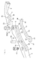
- the more specific construction of the temple 2 is such that its front side portion comprises projections 12 and 13 which are opposed in up and down direction, and a free groove 15 is formed between the projections.
- the forward ends of the upper and lower projections 12 and 13 are formed to be the connecting members 3 and 5, and shaft holes 17 and 19 (Figs. 3 and 4) are coaxiallly formed with the connecting members 3 and 5.
- the intermediate connecting member 7 is projecting in the inside of the rear portion of the armor 6, and a shaft hole 20 is formed with the connecting member 7 to fit the shaft holes 17 and 19.
- the temple 2 is foldable by insertting the pivot shaft 9 into the shaft holes 17, 19 and 20 which are fit to one another. In a state that the temple 2 is unfolded, a rear portion 21 of the armor is fit into the open groove 15 of the temple from the outside thereof, as shown in Figs. 1 and 5.
- a control projection 22 which is positioned rearwardly of the intermediate connecting member 7, and a press projection 23 is also provided rearwardly of the control projection 22, as shown in Figs. 3 and 5.
- the spring 11 is composed such that a line material such as ⁇ -titanium having flexibility is cut into a predetermined length and given necessary treatment.
- An inserting portion 24 of the spring 11, which is fit into the long concave groove 16, provides an attaching portion 25 at a portion adjacent to its rear end.
- the spring 11 is fixed to upper and lower groove walls 29 and 30 of the long concave groove 16 by a screw 27 which is inserted into an insertion hole 26 whcich penetrates the attaching portion 25.
- An outer surface 31 of the inserting portion 24 contacts a bottom surface 32 of the long concave groove 16, as shown in Fig.5, so that rotation of the spring 11 is prevented about an axis of the screw 27. As shown in Figs.
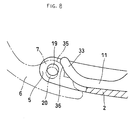
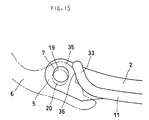
- a flexible press portion 33 forming a front portion of the spring 11, which is slightly bent inwardly, presses flexibly an arc periphery 35 of the intermediate connecting member 7, from the inside of the armor.
- the arc periphery is formed about a center of the shaft hole 20 or a center of the shaft 9.
- a portion of the flexible press portion 33, which contacts the arc periphery 5, is formed to be a curved surface 36 which contacts the arc periphert by face to face contact.
- the temple 2 of unfolded state projecting rearwardly of the eyeglasses, keeps its unfoled state by contacting the control projection 22 of the armor 6 with an outer surface 37 of the front portion of the spring.
- the temple 2 of unfolded state is foldable with necessary frictional force while keeping flexible pressing state, as shown with an alternate long and short dash line in Fig. 5, and therefore the temple 2 may be opened and closed with constant hardness.
- Fig. 6 shows a state that the temple is on the way of folding.
- the temple 2 of unfolded state may be flexibly opened outwardly at a predetermined angle against an urged action of the spring 11.
- the control projection 22 presses the spring 11 inwardly so as to flexibly deform or transform the spring 11.
- Fig. 5 shows a state that the spring is just in a position prior to pressing.
- the spring 11 is pressed inwardly so as to flexibly deform or transform the spring 11 with cooperative function of the control projection and the press projection 23 or the press projection 23 only.
- the spring hinge 1 of the above mentioned construction is composed as follows, as shown in Figs. 2 and 5.
- the intermediate connecting member 7, provided on the side of the armor, is inserted between the upper and lower connecting members 3 and 5 which are provided on the side of the temple, and the shaft holes 17, 19 and 20 are fift coaxially so that the pivot shaft 9 may be inserted thereinto so as to connect the connecting members 3, 5 and 7 together.
- the shaft hole 20 of the connecting member 7 is not fit coaxially to the shaft holes 17 and 19 only by inserting the intermediate connecting member 7 into the upper and lower connecting members 3 and 5.
- the intermediate connecting member 7 is assembled with the upper and lower connecting members 3 and 5 in such a state of placing the flexible press portion 33 of the spring 11 that it is flexibly pressed inwardly.
- the curved surface 36 which contacts the arc periphery 35 of the intermediate connecting member with face to face contact, is formed with the flexible press portion 33 of the spring 11, the curved surface 36 prevents the flexible press portion 33 and the arc periphery 35 from slipping each other when the shaft holes 17, 19 and 20 are fit coaxially by assembling the up and down connecting members 3 and 5 and the intermediate connecting member 7. Thereby, it becomes possible to easily insert the intermediate connecting member 7 into the upper and lower connecting members 3 and 5 and also connect the three members by means of the pivot shaft 9.
- Fig. 9 shows another aspect of the spring hinge 1, which is provided on the side of the temple, in eyeglasses G similar to one which is referred to in the first embodiment.
- an intermediate connecting member 7 is inserted between upper and lower connecting members 3 and 5, which are provided in a state of facing each other leaving a predetermined distance in up and down directions.
- the intermediate connecting member 7 is, for example, provided at a rear portion of an armor 6 which is bent in the form of an L-letter.
- the connecting members 3, 5 and 7 are connected to one another by a pivot shaft 9 (Fig. 11) as a caulking pin 9a by which an tip end portion 8 is caulked as shown in Fig. 4.
- the temple 2 is so composed to be foldable so as to overlap an eyeglass front 10 as shown by an alternate long and short dash line in Fig.
- the temple 2 can be opened and closed with a suitable hardness by an urged action of a spring member 11 which is assembled, and the temple 2 in the unfolded state is also composed to be able to open outwardly at a predetermined angle against an urged action of the spring 11, as shown in Fig. 14.
- the more specific construction of the temple 2 is such that its front side portion comprises projections 12 and 13 which are opposed in up and down direction, and a free groove 39 is formed between the projections.
- the spring hinge of the first embodiment it provide a construction that a bottom surface 40 of the long concave groove 16 is cut off (Figs. 1 and 5), and therefore the lengthes of up and down projections 12 and 13 are longer than those of the first embodiment.
- the forward ends of the up and down projections 12 and 13 are formed to be the connecting members 3 and 5, and shaft holes 17 and 19 (Fig. 11) are coaxiallly formed with the connecting members 3 and 5
- the intermediate connecting member 7 is projecting in the inside of the rear portion of the armor 6, and a shaft hole 20 is formed with the connecting member 7 to fit the shaft holes 17 and 19.
- the temple 2 is foldable by insertting the pivot shaft 9 into the shaft holes 17, 19 and 20 which are fit to one another. In a state that the temple 2 is unfolded, a rear portion 21 of the armor is fit into the open groove 39 of the temple from the outside thereof, as shown in Figs. 9 and 12.
- a control projection 22 which is positioned rearwardly of the intermediate connecting member 7, and a press projection 23 is also provided rearwardly of the control projection 22, as shown in Figs. 11 and 12.
- the spring 11 is composed such that a line material such as ⁇ -titanium having flexibility is cut into a predetermined length and given necessary treatment.
- a flexible press portion 33 forming a front portion of the spring 11, which is slightly bent inwardly, presses flexibly an arc periphery 35 of the intermediate connecting member 7, from the inside of the armor.
- the arc periphery is formed about a center of the shaft hole 20 or a center of the shaft 9.
- a portion of the flexible press portion 33, which contacts the arc periphery 5, is formed to be a curved surface 36 which contacts the arc periphert by face to face contact.
- the temple 2 of unfolded state projecting rearwardly of the eyeglasses, keeps its unfoled state by contacting the control projection 22 of the armor 6 with an outer surface 37 of the front portion of the spring.
- the temple 2 of unfolded state is foldable with necessary frictional force while keeping flexible pressing state, as shown with an alternate long and short dash line in Fig. 12, and therefore the temple 2 may be opened and closed with constant hardness.
- Fig. 13 shows a state that the temple is on the way of folding.
- the temple 2 of unfolded state may be flexibly opened outwardly at a predetermined angle against an urged action of the spring 11.
- the control projection 22 presses the spring 11 inwardly so as to flexibly deform the spring 11.
- Fig. 12 shows a state that the spring is just in a position prior to pressing.
- the spring 11 is pressed inwardly so as to flexibly deform or transform the spring 11 with cooperative function of the control projection and the press projection 23 or the press projection 23 only.
- the spring hinge 1 of the above mentioned construction is composed as follows, as shown in Figs. 10 and 12.
- the intermediate connecting member 7, provided on the side of the armor is inserted between the upper and lower connecting members 3 and 5 which are provided on the side of the temple, and the shaft holes 17, 19 and 20 are fift coaxially so that the pivot shaft 9 may be inserted thereinto so as to connect the connecting members 3, 5 and 7 together.
- the shaft hole 20 of the connecting member 7 is not fit coaxially to the shaft holes 17 and 19 only by inserting the intermediate connecting member 7 into the upper and lower connecting members 3 and 5. Therefore, it is necessary that the intermediate connecting member 7 is assembled with the upper and lower connecting members 3 and 5 in such a state of placing the flexible press portion 33 of the spring 11 that it is flexibly pressed inwardly.
- the curved surface 36 which contacts the arc periphery 35 of the intermediate connecting member with face to face contact, is formed with the flexible press portion 33 of the spring 11, the curved surface 36 prevents the flexible press portion 33 and the arc periphery 35 from slipping each other when the shaft holes 17, 19 and 20 are fit coaxially by assembling the upper and lower connecting members 3 and 5 and the intermediate connecting member 7.
- the first embodiment it becomes possible to easily insert the intermediate connecting member 7 into the upper and lower connecting members 3 and 5 and also connect the three members by means of the pivot shaft 9.
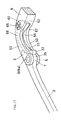
- the inside of the middle portion of the spring 11 may be supported by means of a support pin 50 which is fixed to the up and down groove walls of the open groove 39, as shown in Figs. 10, 12 and 14, so that it becomes possible to increase the urging force of a relatively short portioin 51 (Fig. 14) which is forming a front of the spring 11.
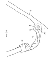
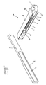
- Fig. 16 shows another aspect of the spring hinge 1, which is utilized for comprising rimless eyeglasses G , in which a lense L is supported on a curved edge frame 44 by means of a cord 48.
- Whole construction of the spring hinge 1 will be described with reference to Figs. 16 through 21.
- an intermediate connecting member 7 is inserted between upper and lower connecting members 3 and 5, which are provided in a state of facing each other leaving a predetermined distance in up and down directions.
- the connecting members 3, 5 and 7 are connected to one another by a pivot shaft 9 (Fig. 18) as a caulking pin 9a which is referred to in the former embodiments.
- the temple 2 is so composed to be foldable so as to overlap an eyeglass front 10 as shown by an alternate long and short dash line in Fig. 12, from a state of unfolded state of Fig. 19, in which the temple is projecting rearwardly of the eyeglasses.
- the temple 2 can be opened and closed with a suitable hardness by an urged action of a spring member 11 which is assembled, and the temple 2 in the unfolded state is also composed to be able to open outwardly at a predetermined angle against an urged action of the spring 11, as shown in Fig. 21.
- the more specific construction of the armor 6 is such that its rear portion comprises projections 52 and 53 which are faced in up and down directions, and an opened groove 55 is formed therebetween.
- the inside of the front portion of the temple 2 provides the intermediate connecting member 6 to project and a shaft hole 20 is formed with the connecting member 7 to fit the shaft holes 17 and 19.
- the temple 2 is foldable by inserting the pivot shaft 9 into the shaft holes 17, 19 and 20, which are positioned to fit one another, and in the unfolded state of the temple 2, a front end portion 56 of the temple is fit into a rear side portion 57 of the open groove 55 which is formed with the armor 6, as shown in Figs. 16 and 19.
- the inside of the temple 2 provides a control projection 59 to locate at a front side of the intermediate connecting member 7, and also a press projection 60 is provided with the front of the control projection 59 continuously.
- the spring 11 is composed such that a line material such as ⁇ -titanium having flexibility is cut into a predetermined length and given necessary treatment so as to form substantiall an L-letter, and then installed in the open groove 55.
- a front end 62 of an expanded portion 61 formed with the spring is engaged with a groove bottom 63 of the open groove 55 and the spring 11 is prevented from rotating about an axis of a screw 65, in such a manner that the up and down ends of a screw 65, which penetrates an insertion hole 64 of the expanded portion 61, are fixed to upper and lower groove walls 66 and 67.
- the arc periphery is formed about a center of the shaft hole 20 or a center of the shaft 9.
- a portion of the flexible press portion 33, which contacts the arc periphery 5, is formed to be a curved surface 36 which contacts the arc periphert by face to face contact.
- the temple 2 of unfolded state projecting rearwardly of the eyeglasses, keeps its unfoled state by contacting the control projection 59 with an outer surface 69 of the rear portion of the spring 11.
- the temple 2 of unfolded state is foldable with necessary frictional force while keeping flexible pressing state, and therefore the temple 2 may be opened and closed with constant hardness.
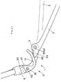
- Fig. 20 shows a state that the temple is on the way of folding.
- the temple 2 of unfolded state may be flexibly opened outwardly at a predetermined angle against an urged action of the spring 11.
- the control projection 59 presses the spring 11 inwardly so as to flexibly deform the spring 11.
- the spring 11 is pressed inwardly so as to flexibly deform the spring 11 with cooperative function of the control projection 59 and the press projection 60 or by the press projection 60 only.
- the spring hinge 1 of the above mentioned construction is composed as follows.
- the intermediate connecting member 7, provided on the side of the temple is inserted between the upper and lower connecting members 3 and 5 which are provided on the side of the armor, and the shaft holes 17, 19 and 20 are fift coaxially so that the pivot shaft 9 may be inserted thereinto so as to connect the connecting members 3, 5 and 7 together.
- the shaft hole 20 of the connecting member 7 is not fit coaxially to the shaft holes 17 and 19 only by inserting the intermediate connecting member 7 into the upper and lower connecting members 3 and 5.
- the intermediate connecting member 7 is assembled with the upper and lower connecting members 3 and 5 in such a state of placing the flexible press portion 33 of the spring 11 that it is flexibly pressed inwardly.
- the curved surface 36 which contacts the arc periphery 35 of the intermediate connecting member with face to face contact, is formed with the flexible press portion 33 of the spring 11, the curved surface 36 prevents the flexible press portion 33 and the arc periphery 35 from slipping each other when the shaft holes 17, 19 and 20 are fit coaxially by assembling the upper and lower connecting members 3 and 5 and the intermediate connecting member 7.
- it may obtain the same result as the former embodiments that it becomes possible to easily insert the intermediate connecting member 7 into the upper and lower connecting members 3 and 5 and also connect the three members by means of the pivot shaft 9.
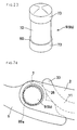
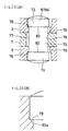
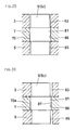
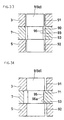
- the pivot shaft 9 for connecting the upper and lower connecting members 3 and 5 and the intermediate connecting member 7, may be composed by the above mentioned caulked pin 9a or a screw, but it may adop the pin 9b having a head as shown in Fig. 23, the pin 9c having a projection 70 therearound at a middle portion thereof as shown in Fig. 27, the pin 9d having a concave groove 71 therearound at a middle portion thereof and so forth.
- This may be introduced in detail as follows, as a modification of the spring hinge 1 of the rimless eyeglasses G , which is, for example, referred to in the first embodiment.
- Fig. 24 shows a construction like one shown in Fig. 23.
- the connecting members 3, 5 and 7 are connected to both ends of a shaft 72, which ends have the same diameter, by means of a pin 9b having a large diameter head 73 which is greater than that of the shaft 72.
- shaft holes 75, 76 and 77 are formed with the upper and lower connecting members 3 and 5 and the intermediate connecting member 7, as shown in Fig. 25.
- the shaft holes have a diameter slightly greater than that of the shaft portion 72, and substantially the same diameter as that of the head 73.
- a receiving hole portion 77 which has a diameter slightly greater than that of the head, is provided via a step 78 in the up and down shaft holes 75 and 76.
- the pin 9b having a head is inserted into the shaft holes 75, 76 and 77, each of the axis of which are fit together, as shown in Fig. 25, so that the head 73 may be positioned in the receiving hole portion.
- the flxible press portion 33 of the spring 11 flexibly presses the arc periphery 35 of the intermediate connecting member 7, as shown in Fig. 24, so that the shaft portion 72 may be moved under pressure of an inside surface 79 of the shaft hole 77 of the connecting member 7, as shown in Fig. 26.
- portions 80a and 80a which form reverse surfaces 80 and 80 of the up and down heads, engage with the step 78 so as to prevent the pin 9b having a head from disengaging.
- Fig. 28 shows a composition that the connecting members 3, 5 and 7 are connected to a part of the periphery of a shaft portion 81, as shown in Fig. 27, by using a pin 9c having a projection 70 which continues in a peripheral direction, wherein it shows a state that the intermediate connecting member 7 is inserted into a shaft hole 86.
- shaft holes 83, 85 and 86 which have a diameter slightly greater than that of the shaft portion 81, are formed with the upper and lower connecting members 3 and 5 and the intermediate connecting member 7.
- the pin 9c having a projection is inserted into the shaft holes 83, 85 and 86 each of the axis of which holes fit to one another, as shown in Fig. 29.
- the flxible press portion 33 of the spring 11 flexibly presses the arc periphery 35 of the intermediate connecting member 7, as shown in Fig. 28, so that the shaft portion 81 may be moved under pressure of an inside surface 87 of the shaft hole 86 of the connecting member 7, and then the up and down shaft holes 83 and 85 are shifted with respect to the intermediate shaft hole 86.
- a portion 70a which forms a froward portion of the projection 70 in its moving direction, becomes in a state that it fits into between the up and down connecting members 3 and 5, so that the pin 9c having a projection may be prevented from disengaging.
- Fig. 32 shows a composition that the connecting members 3, 5 and 7 are connected to a part of the periphery of a shaft portion 89, as shown in Fig. 31, by using a pin 9d having a concave groove 71 which is continuously formed therewith in a peripheral direction, wherein it shows a state that the intermediate connecting member 7 is inserted into a shaft hole 93.
- shaft holes 91, 92 and 93 which have a diameter slightly greater than that of the shaft portion 89, are formed with the upper and lower connecting members 3 and 5 and the intermediate connecting member 7.
- the pin 9d having a groove is inserted into the shaft holes 91, 92 and 93, each of the axis of which holes fit to one another, as shown in Fig. 33.
- the flxible press portion 33 of the spring 11 flexibly presses the arc periphery 35 of the intermediate connecting member 7, as shown in Fig. 32, so that the shaft portion 89 may be moved under pressure of an inside surface 95 of the shaft hole 93 of the connecting member 7, and then the up and down shaft holes 91 and 92 are shifted with respect to the intermediate shaft hole 93.
- the spring 11 is not limited to one like a line which is mentioned above. 3 ⁇
- attaching means of the spring 11 to the temple or the armor it may adopt such means, for example, caulked pin, brazing, adhesion and the like, other than the above mentioned screw means.
Landscapes
- Physics & Mathematics (AREA)
- Health & Medical Sciences (AREA)
- General Physics & Mathematics (AREA)
- Ophthalmology & Optometry (AREA)
- Optics & Photonics (AREA)
- Eyeglasses (AREA)
Applications Claiming Priority (2)
| Application Number | Priority Date | Filing Date | Title |
|---|---|---|---|
| JP31961698 | 1998-11-10 | ||
| JP10319616A JP2975361B1 (ja) | 1998-11-10 | 1998-11-10 | 眼鏡用のバネ蝶番 |
Publications (2)
| Publication Number | Publication Date |
|---|---|
| EP1001302A1 true EP1001302A1 (de) | 2000-05-17 |
| EP1001302B1 EP1001302B1 (de) | 2002-03-13 |
Family
ID=18112280
Family Applications (1)
| Application Number | Title | Priority Date | Filing Date |
|---|---|---|---|
| EP99308931A Expired - Lifetime EP1001302B1 (de) | 1998-11-10 | 1999-11-09 | Federscharnier für Brillen |
Country Status (4)
| Country | Link |
|---|---|
| US (1) | US6336250B1 (de) |
| EP (1) | EP1001302B1 (de) |
| JP (1) | JP2975361B1 (de) |
| DE (1) | DE69901017T2 (de) |
Cited By (6)
| Publication number | Priority date | Publication date | Assignee | Title |
|---|---|---|---|---|
| WO2003061101A1 (en) * | 2002-01-17 | 2003-07-24 | Mitsui High-Tec. Inc. | Production method for amorphous laminate core and amorphous laminate core |
| WO2005001551A1 (en) * | 2003-06-30 | 2005-01-06 | Safilo Societa' Azionaria Fabbrica Italiana Lavorazione Occhiali S.P.A. | A hinge for a spectacle frame and a frame including such a hinge |
| FR2997769A1 (fr) * | 2012-11-08 | 2014-05-09 | Marius Morel France Sas | Charniere et branche de lunettes |
| WO2021211336A1 (en) * | 2020-04-17 | 2021-10-21 | Bose Corporation | Audio eyeglasses with double-detent hinge |
| US11513366B2 (en) | 2020-01-31 | 2022-11-29 | Bose Corporation | Audio eyeglasses with double-detent hinge |
| US11662609B2 (en) | 2020-01-31 | 2023-05-30 | Bose Corporation | Wearable audio device with cable-through hinge |
Families Citing this family (33)
| Publication number | Priority date | Publication date | Assignee | Title |
|---|---|---|---|---|
| WO2004003243A1 (en) * | 2002-06-27 | 2004-01-08 | Memry Corporation | METHOD FOR MANUFACTURING SUPERELASTIC β TITANIUM ARTICLES AND THE ARTICLES DERIVED THEREFROM |
| US20040261912A1 (en) * | 2003-06-27 | 2004-12-30 | Wu Ming H. | Method for manufacturing superelastic beta titanium articles and the articles derived therefrom |
| US20040168751A1 (en) * | 2002-06-27 | 2004-09-02 | Wu Ming H. | Beta titanium compositions and methods of manufacture thereof |
| US6623115B1 (en) * | 2002-08-09 | 2003-09-23 | Ching Lan Co., Ltd. | Guiding washer for a hinge of an eyeglass frame |
| US6659606B1 (en) | 2003-03-12 | 2003-12-09 | Arthur G. Duppstadt | Alignment apparatus for an eyeglass hinge assembly and method employing same |
| US8100956B2 (en) * | 2006-05-09 | 2012-01-24 | Thermotek, Inc. | Method of and system for thermally augmented wound care oxygenation |
| US8944590B2 (en) | 2010-07-02 | 2015-02-03 | Mitsui Chemicals, Inc. | Electronic spectacle frames |
| US12572035B2 (en) | 2007-05-04 | 2026-03-10 | E-Vision Optics, Llc | Moisture-resistant eye wear |
| US10613355B2 (en) | 2007-05-04 | 2020-04-07 | E-Vision, Llc | Moisture-resistant eye wear |
| US8783861B2 (en) | 2010-07-02 | 2014-07-22 | Pixeloptics, Inc. | Frame design for electronic spectacles |
| US8979259B2 (en) | 2010-07-02 | 2015-03-17 | Mitsui Chemicals, Inc. | Electro-active spectacle frames |
| US8905541B2 (en) | 2010-07-02 | 2014-12-09 | Mitsui Chemicals, Inc. | Electronic spectacle frames |
| US11061252B2 (en) | 2007-05-04 | 2021-07-13 | E-Vision, Llc | Hinge for electronic spectacles |
| US8801174B2 (en) | 2011-02-11 | 2014-08-12 | Hpo Assets Llc | Electronic frames comprising electrical conductors |
| WO2010080999A1 (en) | 2009-01-09 | 2010-07-15 | Pixeloptics, Inc. | Electro-active spectacles and associated electronics |
| CN101639574B (zh) | 2009-08-31 | 2013-09-18 | 深圳市龙岗区横岗镇高雅眼镜厂 | 眼镜弹片铰链 |
| US8444265B2 (en) * | 2009-10-02 | 2013-05-21 | Oakley, Inc. | Eyeglass earstem with enhanced performance |
| US8020988B2 (en) * | 2009-11-06 | 2011-09-20 | Oakley, Inc. | Eyeglass earstem with enhanced performance |
| JP5474585B2 (ja) * | 2010-01-25 | 2014-04-16 | 株式会社フォーナインズ | 眼鏡フレーム |
| USD650825S1 (en) | 2010-02-05 | 2011-12-20 | Oakley, Inc. | Eyeglass and eyeglass component |
| US12436411B2 (en) | 2010-07-02 | 2025-10-07 | E-Vision Optics, Llc | Moisture-resistant eye wear |
| TW201227047A (en) | 2010-07-09 | 2012-07-01 | Pixeloptics Inc | Electro-active spectacle frames |
| TW201234070A (en) | 2010-11-19 | 2012-08-16 | Pixeloptics Inc | Electronic spectacle frames |
| USD652442S1 (en) | 2011-01-18 | 2012-01-17 | Oakley, Inc. | Eyeglass |
| CN103339551A (zh) | 2011-01-27 | 2013-10-02 | 绿安全股份有限公司 | 眼镜 |
| US12510773B2 (en) | 2011-02-11 | 2025-12-30 | E-Vision Optics, Llc | Moisture-resistant eye wear |
| EP3264163A1 (de) | 2011-08-17 | 2018-01-03 | Mitsui Chemicals, Inc. | Feuchtigkeitsbeständige gestelle für elektronische brillen |
| ITUB20160923A1 (it) * | 2016-02-22 | 2017-08-22 | Safilo Sa Fabbrica Italiana Lavorazione Occhiali Spa | Montatura per occhiali |
| JP6779514B2 (ja) * | 2016-08-02 | 2020-11-04 | 川本光学工業株式会社 | 眼鏡枠 |
| EP3364235B1 (de) * | 2017-02-17 | 2021-06-09 | M Group S.à.r.l. | Brille mit schraubenlosen elastischen scharnier |
| CH715026A9 (de) * | 2018-05-28 | 2020-01-15 | Simon Kraehenbuehl | Brillengestell. |
| WO2021029316A1 (ja) * | 2019-08-09 | 2021-02-18 | 三井化学株式会社 | フレーム及びアイウェア |
| CN116009262A (zh) * | 2023-01-04 | 2023-04-25 | 湖北星纪时代科技有限公司 | 一种铰接结构和智能眼镜 |
Citations (3)
| Publication number | Priority date | Publication date | Assignee | Title |
|---|---|---|---|---|
| EP0115826A2 (de) * | 1983-02-04 | 1984-08-15 | CELES OPTICAL S.r.l. | Federscharnier für Brillenbügel |
| DE8812332U1 (de) * | 1988-09-29 | 1988-11-10 | Marwitz & Hauser GmbH, 7000 Stuttgart | Scharnier insbesondere für Brillenfassungen |
| FR2703477A1 (fr) * | 1993-03-30 | 1994-10-07 | Piard Gerard | Charnière, notamment pour monture de lunettes. |
Family Cites Families (10)
| Publication number | Priority date | Publication date | Assignee | Title |
|---|---|---|---|---|
| US2087502A (en) * | 1936-02-28 | 1937-07-20 | Leo T Chylack | Spectacles |
| US3102156A (en) * | 1961-01-03 | 1963-08-27 | Bausch & Lomb | Combination temple "no-drop" brake and screw guard |
| US3145254A (en) * | 1962-04-02 | 1964-08-18 | Bausch & Lomb | Ophthalmic mounting |
| FR2194981B1 (de) * | 1972-08-02 | 1983-11-04 | Maillet Rene | |
| US3923384A (en) * | 1974-10-03 | 1975-12-02 | Foster Grant Co Inc | Self adjusting spectacle frame assembly |
| IT207535Z2 (it) * | 1986-03-03 | 1988-01-25 | Celes Optical | Cerniera elastica regolabile particolarmente per astine di occhiali. |
| DE3727706A1 (de) * | 1987-08-19 | 1989-03-02 | Rodenstock Optik G | Gangregulierung fuer scharniere |
| US5666181A (en) * | 1996-04-11 | 1997-09-09 | Bausch & Lomb Incorporated | Spring temple for eyewear |
| JPH10133153A (ja) * | 1996-10-30 | 1998-05-22 | Shiyuuyuu:Kk | メガネフレームのツル継手構造 |
| JP3966609B2 (ja) * | 1998-04-07 | 2007-08-29 | 川本光学工業株式会社 | 眼鏡用ヒンジ |
-
1998
- 1998-11-10 JP JP10319616A patent/JP2975361B1/ja not_active Expired - Fee Related
-
1999
- 1999-11-09 DE DE69901017T patent/DE69901017T2/de not_active Expired - Fee Related
- 1999-11-09 EP EP99308931A patent/EP1001302B1/de not_active Expired - Lifetime
- 1999-11-10 US US09/437,340 patent/US6336250B1/en not_active Expired - Fee Related
Patent Citations (3)
| Publication number | Priority date | Publication date | Assignee | Title |
|---|---|---|---|---|
| EP0115826A2 (de) * | 1983-02-04 | 1984-08-15 | CELES OPTICAL S.r.l. | Federscharnier für Brillenbügel |
| DE8812332U1 (de) * | 1988-09-29 | 1988-11-10 | Marwitz & Hauser GmbH, 7000 Stuttgart | Scharnier insbesondere für Brillenfassungen |
| FR2703477A1 (fr) * | 1993-03-30 | 1994-10-07 | Piard Gerard | Charnière, notamment pour monture de lunettes. |
Cited By (7)
| Publication number | Priority date | Publication date | Assignee | Title |
|---|---|---|---|---|
| WO2003061101A1 (en) * | 2002-01-17 | 2003-07-24 | Mitsui High-Tec. Inc. | Production method for amorphous laminate core and amorphous laminate core |
| US7103961B2 (en) | 2002-01-17 | 2006-09-12 | Mitsui High-Tec, Inc. | Production method of amorphous laminate core and amorphous laminate core |
| WO2005001551A1 (en) * | 2003-06-30 | 2005-01-06 | Safilo Societa' Azionaria Fabbrica Italiana Lavorazione Occhiali S.P.A. | A hinge for a spectacle frame and a frame including such a hinge |
| FR2997769A1 (fr) * | 2012-11-08 | 2014-05-09 | Marius Morel France Sas | Charniere et branche de lunettes |
| US11513366B2 (en) | 2020-01-31 | 2022-11-29 | Bose Corporation | Audio eyeglasses with double-detent hinge |
| US11662609B2 (en) | 2020-01-31 | 2023-05-30 | Bose Corporation | Wearable audio device with cable-through hinge |
| WO2021211336A1 (en) * | 2020-04-17 | 2021-10-21 | Bose Corporation | Audio eyeglasses with double-detent hinge |
Also Published As
| Publication number | Publication date |
|---|---|
| JP2975361B1 (ja) | 1999-11-10 |
| DE69901017D1 (de) | 2002-04-18 |
| DE69901017T2 (de) | 2002-10-17 |
| JP2000147438A (ja) | 2000-05-26 |
| US6336250B1 (en) | 2002-01-08 |
| EP1001302B1 (de) | 2002-03-13 |
Similar Documents
| Publication | Publication Date | Title |
|---|---|---|
| EP1001302A1 (de) | Federscharnier für Brillen | |
| US5760869A (en) | Eyeglasses frame with spring hinges | |
| US7543931B2 (en) | Glasses frame | |
| JP2007537468A (ja) | メガネ | |
| AU2665197A (en) | Spring temple for eyewear | |
| JP3058787U (ja) | メガネフレーム | |
| US6050685A (en) | Eyeglasses without a frame | |
| JP2609994B2 (ja) | 眼鏡つる | |
| JP4414791B2 (ja) | 眼鏡のばね蝶番及びこの組立方法 | |
| JP3345407B2 (ja) | 眼鏡のテンプル連結構造 | |
| JPH1039261A (ja) | ヒンジレス眼鏡テンプルの折り畳み機構 | |
| EP1489452B1 (de) | Scharnier ohne Schraube für eine Brillenfassung | |
| JP3785168B2 (ja) | 眼鏡枠 | |
| JP3046037U (ja) | 眼鏡のバネ丁番機構 | |
| KR102906731B1 (ko) | 안경테와 다리의 힌지구조체 | |
| JP3003386U (ja) | 眼 鏡 | |
| CN222813024U (zh) | 一种方便拆卸更换的镜腿结构 | |
| JP4115566B2 (ja) | バンドとケースの連結構造 | |
| JP2007024955A (ja) | メガネフレームのツル取付け構造 | |
| JP3124644U (ja) | 眼鏡フレーム用テンプル、眼鏡フレームおよび眼鏡フレーム用取り付け具 | |
| JP3006427U (ja) | 縁なし眼鏡 | |
| TWI824539B (zh) | 眼鏡及鏡框 | |
| JP3007096U (ja) | フイッティング機構を具えた眼鏡つる | |
| CN212933172U (zh) | 一种眼镜桩头与镜腿连接的弹性铰链结构 | |
| JPH03122611A (ja) | 眼鏡テンプルのスプリング蝶番、および同スプリング蝶番を用いた眼鏡 |
Legal Events
| Date | Code | Title | Description |
|---|---|---|---|
| PUAI | Public reference made under article 153(3) epc to a published international application that has entered the european phase |
Free format text: ORIGINAL CODE: 0009012 |
|
| 17P | Request for examination filed |
Effective date: 19991130 |
|
| AK | Designated contracting states |
Kind code of ref document: A1 Designated state(s): DE FR IT |
|
| AX | Request for extension of the european patent |
Free format text: AL;LT;LV;MK;RO;SI |
|
| 17Q | First examination report despatched |
Effective date: 20001130 |
|
| AKX | Designation fees paid |
Free format text: DE FR IT |
|
| GRAG | Despatch of communication of intention to grant |
Free format text: ORIGINAL CODE: EPIDOS AGRA |
|
| GRAG | Despatch of communication of intention to grant |
Free format text: ORIGINAL CODE: EPIDOS AGRA |
|
| GRAH | Despatch of communication of intention to grant a patent |
Free format text: ORIGINAL CODE: EPIDOS IGRA |
|
| GRAG | Despatch of communication of intention to grant |
Free format text: ORIGINAL CODE: EPIDOS AGRA |
|
| GRAH | Despatch of communication of intention to grant a patent |
Free format text: ORIGINAL CODE: EPIDOS IGRA |
|
| GRAA | (expected) grant |
Free format text: ORIGINAL CODE: 0009210 |
|
| AK | Designated contracting states |
Kind code of ref document: B1 Designated state(s): DE FR IT |
|
| REF | Corresponds to: |
Ref document number: 69901017 Country of ref document: DE Date of ref document: 20020418 |
|
| ET | Fr: translation filed | ||
| PLBE | No opposition filed within time limit |
Free format text: ORIGINAL CODE: 0009261 |
|
| STAA | Information on the status of an ep patent application or granted ep patent |
Free format text: STATUS: NO OPPOSITION FILED WITHIN TIME LIMIT |
|
| 26N | No opposition filed |
Effective date: 20021216 |
|
| PG25 | Lapsed in a contracting state [announced via postgrant information from national office to epo] |
Ref country code: IT Free format text: LAPSE BECAUSE OF NON-PAYMENT OF DUE FEES Effective date: 20051109 |
|
| PGFP | Annual fee paid to national office [announced via postgrant information from national office to epo] |
Ref country code: FR Payment date: 20081117 Year of fee payment: 10 |
|
| PGFP | Annual fee paid to national office [announced via postgrant information from national office to epo] |
Ref country code: DE Payment date: 20090128 Year of fee payment: 10 |
|
| PGFP | Annual fee paid to national office [announced via postgrant information from national office to epo] |
Ref country code: IT Payment date: 20081127 Year of fee payment: 10 |
|
| PGRI | Patent reinstated in contracting state [announced from national office to epo] |
Ref country code: IT Effective date: 20091201 |
|
| REG | Reference to a national code |
Ref country code: FR Ref legal event code: ST Effective date: 20100730 |
|
| PG25 | Lapsed in a contracting state [announced via postgrant information from national office to epo] |
Ref country code: FR Free format text: LAPSE BECAUSE OF NON-PAYMENT OF DUE FEES Effective date: 20091130 |
|
| PG25 | Lapsed in a contracting state [announced via postgrant information from national office to epo] |
Ref country code: DE Free format text: LAPSE BECAUSE OF NON-PAYMENT OF DUE FEES Effective date: 20100601 |
|
| PGRI | Patent reinstated in contracting state [announced from national office to epo] |
Ref country code: IT Effective date: 20091201 |