EP1001321A2 - Commande pour un appareil électrique - Google Patents
Commande pour un appareil électrique Download PDFInfo
- Publication number
- EP1001321A2 EP1001321A2 EP99120495A EP99120495A EP1001321A2 EP 1001321 A2 EP1001321 A2 EP 1001321A2 EP 99120495 A EP99120495 A EP 99120495A EP 99120495 A EP99120495 A EP 99120495A EP 1001321 A2 EP1001321 A2 EP 1001321A2
- Authority
- EP
- European Patent Office
- Prior art keywords
- control
- control unit
- electrical device
- electrical
- control according
- Prior art date
- Legal status (The legal status is an assumption and is not a legal conclusion. Google has not performed a legal analysis and makes no representation as to the accuracy of the status listed.)
- Granted
Links
Images
Classifications
-
- F—MECHANICAL ENGINEERING; LIGHTING; HEATING; WEAPONS; BLASTING
- F24—HEATING; RANGES; VENTILATING
- F24C—DOMESTIC STOVES OR RANGES ; DETAILS OF DOMESTIC STOVES OR RANGES, OF GENERAL APPLICATION
- F24C7/00—Stoves or ranges heated by electric energy
- F24C7/08—Arrangement or mounting of control or safety devices
- F24C7/082—Arrangement or mounting of control or safety devices on ranges, e.g. control panels, illumination
-
- G—PHYSICS
- G05—CONTROLLING; REGULATING
- G05B—CONTROL OR REGULATING SYSTEMS IN GENERAL; FUNCTIONAL ELEMENTS OF SUCH SYSTEMS; MONITORING OR TESTING ARRANGEMENTS FOR SUCH SYSTEMS OR ELEMENTS
- G05B19/00—Program-control systems
- G05B19/02—Program-control systems electric
- G05B19/04—Program control other than numerical control, i.e. in sequence controllers or logic controllers
- G05B19/042—Program control other than numerical control, i.e. in sequence controllers or logic controllers using digital processors
- G05B19/0423—Input/output
Definitions
- the invention relates to a control for an electrical device with at least one electrical contained in the device Functional device, wherein the controller at least one Power switching device contains.
- the Invention application to an electric heating device, in particular a household electric cooker or oven.
- DE-U 296 22 066 proposes a domestic appliance, which is being expanded the usual design at least one separate operating and / or Display element is assigned. This is similar to the Functional principle forth for example a remote control for a television in which, so to speak, from the electrical appliance separate control buttons or switches are included. In addition, there is a bidirectional data transmission provided to be on a separate from the electrical device Read off display-relevant data.
- DE 196 15 357 contains solutions have been proposed, where only separate display elements provided for the operating state of the electrical device are the program parameters set on the electrical device get saved and then the corresponding one Reconstruct and display the program flow internally.
- EP 846 991 describes a household appliance network a central control computer for monitoring. For improved This central monitoring is the availability of information with a mobile display device on one side Telecontrol technology connected.
- a display device transmits data relating to the defect via the transmission device and telephone network to a diagnostic center, in particular a computer at a customer service center or the like
- the invention has for its object one described above To create control that the disadvantages of State of the art avoids the operation of electrical devices improved and diverse applications opened.
- the controller has one of the electrical devices separate, separable or removable control unit, which wirelessly transmit signals with the electrical device connected is.
- wireless or contactless telecontrol technologies can for example connect to infrared or by means of electromagnetic waves.
- the separate control unit essentially contains the Control and regulation part for the electrical device that the at least one power switching device, preferably is installed in the electrical device. Is preferred the entire control and regulation part in the control unit arranged, except for sensors contained in the electrical device o.
- the measured or control variables deliver. So it happens a spatial separation of the control into a power switching part, who sits in the electrical device, and a control and Control part, which is arranged in the separate control unit is.
- the control unit can have a processing device, preferably at least one microprocessor. This processing facility can essentially the control and regulation part form for the electrical appliance.
- the control unit advantageously has input means for input assigned by control commands and the like, in particular Switches such as touch switches, rotary switches and / or pressure switch.
- the control unit is preferably housed with the input means in a control panel, the but a full-fledged one compared to conventional remote controls Can be remote control.
- the controller can have a memory in which among other things different program sequences for the Control and / or parameters of evaluation functions of the Electrical device can be stored. Such parameters of evaluation functions can, for example, when setting up the Electrical device can be determined and stored. Possible is also a storage of series-specific Electrical appliance data.
- Transmission devices can be in the electrical device and Control unit for wireless signal transmission for or exist within the control. Preferably work the transmission devices bidirectional, that means both in the control unit and in that in the electrical device seated part of the controller is both a transmit and also a receiving device installed. It is possible that the control display means for displaying the operating state assigned to the control and / or the electrical device are preferably arranged in the separate control unit are. Display means can, for example, simple illuminated displays, LC displays as well as alphanumeric displays.
- the electrical device can be equipped with sensors for monitoring the Operating state, for example one of the functional units, be provided.
- the signals from such sensors can be on the controller or the control unit are given, the thus, for example, control loops for the electrical device can form, or these operating states by means of display on the control unit for informing a user represent.
- the controller and / or the electrical device can be a location detection device to record the spatial assignment the control unit to the electrical device.
- the spatial Assignment can, for example, be at least one certain position of the control unit according to direction / distance be given, which is essentially a precise location or can be a limited area. It is possible that Control unit, for example, within a certain Detect distance to the electrical device.
- An alternative can be a specific position of the control unit, in particular on the top of the electrical device itself or a place freely accessible to a user. This particular Position can be marked, for example optically by means of colored markings or mechanical stops or rest.
- Such a location detection device makes it possible, for example, only then with the control unit to operate when the control unit in the specific position is. This allows incorrect operation as well as operation by unintended users, for example by avoid children playing on a household appliance; the Control unit is simply separated from the device on one kept in an inaccessible place.
- a contactless location detection device in particular wireless with a transmitter and a receiver, wherein the receiving device is preferably in the Control unit is included.
- Contactless can be preferred here mean that the location recording without any contact to the Capture works in itself.
- the location detection device can work inductively, for example.
- An alternative to a location detection device can be a with the electrical device and / or the control system connected and attached to a predetermined position Station and / or bracket on which the control unit What is to be communicated to the controller must be attached.
- a particularly easy detection of a station attached Control unit can be done by actuated contacts.
- Control unit can be holding means for detachable without tools Fixation can be provided in a certain position.
- This Holding means can preferably be magnetic holding means and / or have magnetic alignment means. these can advantageous under smooth, unbroken surfaces such as For example, glass surfaces or the like are attached.
- the Holding means can also be part of a location detection device for the control unit.
- the control unit can be equipped with a own source, preferably one again rechargeable energy storage, such as an accumulator.
- Prefers becomes a power supply with which the control unit can be released is connectable, such a connection preferably a specific spatial assignment of the control unit to the Electrical device conditional. Accordingly, the control unit can only work when it is supplied with energy for which it is must be in a particular position described above.
- a Double function of the transmission devices for example with separate transmission windows, reduces the effort.
- the controller can, especially in the in the electrical device contained part, contain a power switching device, those for interacting with different control units or types of control units.
- These different Control units each contain the control and Control part for the electrical device, being different Functional features with regard to equipment, control options or the like. That way it is possible, both simple control units with pure controls to be provided as well as further upgraded control units, the additional functions such as timers, program sequences etc. have.
- a basic version of an electrical device can be individually retrofitted or upgraded, all the additional functions required as an upgrade are realized in the control unit.
- a control according to the invention can be particularly preferred in an electric heater with a cooktop can be installed, which consists in particular of glass ceramic.
- One described above separate control unit can go to a given location Can be positioned on the hob and thus like one this point fixed operating unit act.
- Advantageous the electrical device can only be used in this position Control unit operated or operated.
- Another advantage of the present invention is that in the event of a malfunction or irreparable damage the entire electrical device including the control system must be replaced, but only the electrical device or the control unit.
- part of the invention is a remotely controllable Electrical device, in particular with one described above
- Control controllable the at least one power switching device contains and essentially free of controls and / or control and regulation parts. It can with different types of control units through wireless Signal transmission can be controlled, these control units are designed as separate units from the electrical device and all control and regulation parts for the electrical device contain.
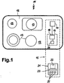
- the drawing shows schematically an electric stove with a controller that is separate from the electrical device Has control unit.
- FIG. 1 shows an electric cooking appliance 11 with a hob 12, the heaters 13 and, by a surrounding Dash-dotting marked as a functional unit, an inventive control 15.
- the schematic held drawing contains the cooking device 11, a power switching device 17, either one or all heaters 13 charged with performance. Your control commands receives the power switching device 17 from the first Transmission device 18, with which it is shown connected is.
- the transmission device 18 is located under a dash mark 19 shown in dashed lines lower right part of the hob 12.
- the electric cooking device 11, or in particular the first transmission device 18, is a separate control unit 21 assigned a second transmission device shown in dashed lines 22, a processing device 23 and Has input and output means 25.
- the second transmission device 22 interacts with the first transmission device 18.
- the processing device 23 preferably has including a microprocessor and a memory for Parameters and / or operations.
- the input and output means 25 can be various switches, for example Touch switches and displays, for example illuminated displays or alphanumeric displays.
- the electric cooking appliance 11 via data transmission between the transmission facilities 18 and 22 and the power switching device 17 are operated or controlled.
- the control commands and / or the operating state of the electric cooking appliance can be connected to the input and Output means 25 are displayed.
- a locking or precise Adherence to the position can on the one hand by stops o.
- a magnetic is advantageous Fixation possible that does not interrupt the smooth surface of the hob 12 is required.
- a location detection device 26 can be a proximity switch, a mechanical switch, or for example a be an inductive sensor.
- This location detection device 26 can be a proximity switch, a mechanical switch, or for example a be an inductive sensor.
- Touch-up mark 19 on the hob 12 are other locations for the control unit 21 is conceivable, on which an attachment is detected and as a prerequisite for operating the electric cooking appliance 11 can be used.
- the control unit 21 contains prefers the entire control and regulation part for that Electric cooking appliance.
- the control unit 21 is in a desired geometric position, is an operation of the Electric cooking appliance 11 only possible. On the one hand, this can by an internal lock, for example in the processing device 23, take place.
- Alternative types of transmission are infrared, Ultrasound, radio or the like
- Control commands from the processing device 23 in Switching commands are implemented, which via the transmission devices 22 and 18 to the power switching device 17 are given. According to the orders, this applies to the Heaters 13.
- the control commands may well under Use information formed from the electrical device become.
- On an output means 25 of the control unit for example one set at a certain level Heater 13 displayed.
- An advantage of the present invention is that, in order to expand the variety of functions of the electrical device 11, only the separate control unit 21 can be replaced got to. For example, in a new control unit Additional functions such as timers, automatic cooking or different program sequences, different pot detection functions or the like. An exchange of the determining part of the controller 15 is in this way simply possible.
- the electric cooking device 11 or the heating devices 13 can sensor devices (not shown) can be assigned, for example temperature sensors or protectors.
- Means the temperature sensors can, for example, be the temperature a heating device 13 can be detected and via the transmission devices 18 and 22 to the control unit 21 and the Processing device 23 are transferred. This information can be used to activate a hot display or for automatic Cooking processes can be used. Protectors are also possible, but in an emergency, the power supply directly to interrupt the heater.
- a power supply to the control unit 21 can either by batteries or accumulators. Alternatively, an inductive power supply is available on the Attachment mark 19 of control unit 21 placed on it. An inductive energy supply can possibly be used in window operation via an inductive data interface.
- a single control unit 21 can be used for a complete family of devices (Hob, oven, extractor hood, microwave oven, etc.) can be used.
- a change can be made either Switching on the control unit or by changing the Touch-up mark or a given position respectively.
- To rationalize the manufacturing process can standardize a few basic models of electric cooking appliances 11 be built up by means of different Control units of different values or equipped Electric cookers result. This has the advantage that before all the power switching devices 17 for a variety be carried out in the same way by different electric cooking appliances can.
- Certain switching or display functions can be carried out on the electrical device are left, for example a general one ON / OFF switch, state lock switch for an Removal of the control unit during operation or hot indicator for a hot heater.
Landscapes
- Engineering & Computer Science (AREA)
- General Physics & Mathematics (AREA)
- Combustion & Propulsion (AREA)
- Mechanical Engineering (AREA)
- General Engineering & Computer Science (AREA)
- Physics & Mathematics (AREA)
- Chemical & Material Sciences (AREA)
- Automation & Control Theory (AREA)
- Electric Stoves And Ranges (AREA)
- Induction Heating Cooking Devices (AREA)
- Selective Calling Equipment (AREA)
- Cookers (AREA)
- Control Of Electric Motors In General (AREA)
- Apparatus For Making Beverages (AREA)
Applications Claiming Priority (2)
| Application Number | Priority Date | Filing Date | Title |
|---|---|---|---|
| DE19849075 | 1998-10-24 | ||
| DE19849075A DE19849075A1 (de) | 1998-10-24 | 1998-10-24 | Steuerung für ein Elektrogerät |
Publications (3)
| Publication Number | Publication Date |
|---|---|
| EP1001321A2 true EP1001321A2 (fr) | 2000-05-17 |
| EP1001321A3 EP1001321A3 (fr) | 2003-05-14 |
| EP1001321B1 EP1001321B1 (fr) | 2007-03-07 |
Family
ID=7885514
Family Applications (1)
| Application Number | Title | Priority Date | Filing Date |
|---|---|---|---|
| EP99120495A Expired - Lifetime EP1001321B1 (fr) | 1998-10-24 | 1999-10-15 | Commande pour un appareil électrique |
Country Status (5)
| Country | Link |
|---|---|
| US (1) | US6198079B1 (fr) |
| EP (1) | EP1001321B1 (fr) |
| AT (1) | ATE356375T1 (fr) |
| DE (2) | DE19849075A1 (fr) |
| ES (1) | ES2281950T3 (fr) |
Cited By (5)
| Publication number | Priority date | Publication date | Assignee | Title |
|---|---|---|---|---|
| EP1107647A3 (fr) * | 1999-12-08 | 2003-01-15 | E.G.O. Elektro-Gerätebau GmbH | Commande pour appareillages électriques, en particulier pour appareils de cuisson électrique |
| DE102006020156A1 (de) * | 2006-05-02 | 2007-11-08 | BSH Bosch und Siemens Hausgeräte GmbH | Kochfeld mit Restwärmeanzeige |
| EP2385312A3 (fr) * | 2010-05-03 | 2011-11-23 | BSH Bosch und Siemens Hausgeräte GmbH | Elément de commande pour un poste de travail ménager, poste de travail ménager, système constitué du poste de travail ménager et de l'élément de commande ainsi que procédé de fonctionnement du système |
| CN107065646A (zh) * | 2017-02-18 | 2017-08-18 | 柳州市第五中学 | 电源排插 |
| EP4703645A1 (fr) * | 2024-08-27 | 2026-03-04 | Whirlpool Corporation | Appareil de cuisson |
Families Citing this family (52)
| Publication number | Priority date | Publication date | Assignee | Title |
|---|---|---|---|---|
| DE10026058A1 (de) * | 2000-05-25 | 2001-11-29 | Ego Elektro Geraetebau Gmbh | Berührungsschalteinrichtung |
| NL1015566C2 (nl) * | 2000-06-29 | 2002-01-02 | Ferro Tech Bv | Voeding voor elektrische huishoudelijke apparatuur en huishoudelijk apparaat, voor samenwerking met een dergelijke voeding. |
| JP2002017058A (ja) * | 2000-06-30 | 2002-01-18 | Mitsubishi Electric Corp | コードレス電力搬送システム、電力搬送端末及び電化機器 |
| USD451483S1 (en) | 2001-01-14 | 2001-12-04 | Sunbeam Products, Inc. | Heating pad controller |
| DE10102588B4 (de) * | 2001-01-20 | 2006-04-20 | AEG Hausgeräte GmbH | Kochmulde |
| US7136914B2 (en) * | 2001-08-06 | 2006-11-14 | Ricoh Company, Ltd. | System, computer program product and method for managing and controlling a local network of electronic devices |
| DE10202493A1 (de) * | 2002-01-23 | 2003-07-31 | Bsh Bosch Siemens Hausgeraete | Bedieneinrichtung für ein Haushaltsgerät |
| US6919815B2 (en) * | 2002-01-24 | 2005-07-19 | Emerson Electric Co. | Appliance control communication methods and apparatus |
| US7109445B2 (en) * | 2002-02-07 | 2006-09-19 | Sunbeam Products, Inc. | Cooking apparatus with electronic recipe display |
| DE10259748A1 (de) * | 2002-12-19 | 2004-07-08 | BSH Bosch und Siemens Hausgeräte GmbH | Dunstabzugshaube und Eingabemodul |
| US20060196979A1 (en) * | 2003-06-10 | 2006-09-07 | Emerson Electric Co. | Audio operation indicator for food waste disposer |
| US7066415B2 (en) * | 2003-06-10 | 2006-06-27 | Emerson Electric Co. | Touch pad control information system for a food waste disposer |
| DE10327273B4 (de) * | 2003-06-17 | 2013-12-24 | BSH Bosch und Siemens Hausgeräte GmbH | Herd mit einem Kochfeld und mit einem Modul zur Steuerung des Kochfeldes |
| US7243174B2 (en) * | 2003-06-24 | 2007-07-10 | Emerson Electric Co. | System and method for communicating with an appliance through an optical interface using a control panel indicator |
| DE10328588A1 (de) * | 2003-06-25 | 2005-03-24 | Siemens Ag | Fernbedienung zur Abgabe von Befehlen an ein fernbedienbares Gerät |
| US7321732B2 (en) * | 2003-07-28 | 2008-01-22 | Emerson Electric Co. | Method and apparatus for improving noise immunity for low intensity optical communication |
| US7280769B2 (en) * | 2003-07-28 | 2007-10-09 | Emerson Electric Co. | Method and apparatus for operating an optical receiver for low intensity optical communication in a high speed mode |
| DE10340627A1 (de) * | 2003-09-03 | 2005-04-07 | Infineon Technologies Ag | Steuerbare Hausgeräte-Anordnung und/oder steuerbare Industriegeräte-Anordnung und Steuersystem zum Steuern einer Hausgeräte-Anordnung und/oder Industriegeräte-Anordnung |
| FR2866512B1 (fr) * | 2004-02-12 | 2006-06-23 | Jaeger Controls | Systeme de table de cuisson electrique |
| US8000816B2 (en) * | 2004-02-28 | 2011-08-16 | Abb Research Ltd | Process control system and method for operating a system of this type |
| DE102004013621A1 (de) * | 2004-03-19 | 2005-10-06 | BSH Bosch und Siemens Hausgeräte GmbH | Fernüberwachungssystem für Dampfgarer und Teile davon |
| US7870232B2 (en) * | 2005-11-04 | 2011-01-11 | Intermatic Incorporated | Messaging in a home automation data transfer system |
| US7694005B2 (en) | 2005-11-04 | 2010-04-06 | Intermatic Incorporated | Remote device management in a home automation data transfer system |
| US7640351B2 (en) * | 2005-11-04 | 2009-12-29 | Intermatic Incorporated | Application updating in a home automation data transfer system |
| US7698448B2 (en) * | 2005-11-04 | 2010-04-13 | Intermatic Incorporated | Proxy commands and devices for a home automation data transfer system |
| US20070121653A1 (en) * | 2005-11-04 | 2007-05-31 | Reckamp Steven R | Protocol independent application layer for an automation network |
| US20070256085A1 (en) * | 2005-11-04 | 2007-11-01 | Reckamp Steven R | Device types and units for a home automation data transfer system |
| DE102006028889B3 (de) * | 2006-06-21 | 2007-07-12 | Miele & Cie. Kg | Haushaltsgerät mit einer Bedientafel, die mindestens ein Beschriftungsfeld aufweist |
| DE102006030550A1 (de) * | 2006-07-03 | 2008-01-17 | BSH Bosch und Siemens Hausgeräte GmbH | Bedieneinheit zur Anzeige und/oder Einstellung von Betriebsparameterwerten von zumindest einem Hausgerät |
| US8230466B2 (en) | 2006-11-16 | 2012-07-24 | At&T Intellectual Property I, L.P. | Home automation system and method including remote media access |
| ITTO20070051A1 (it) * | 2007-01-24 | 2008-07-25 | Indesit Co Spa | Utenza elettrica, in particolare un elettrodomestico, relativo dispositivo ausiliario opzionale e sistema comprendente tali utenza e dispositivo |
| US20090090704A1 (en) * | 2007-10-09 | 2009-04-09 | Halpin Mark E | Pager system for cooking device |
| DE102009000909B4 (de) | 2009-02-17 | 2020-01-23 | BSH Hausgeräte GmbH | Anordnung zur Zubereitung von Lebensmitteln |
| DE102009002774A1 (de) | 2009-04-30 | 2010-11-04 | BSH Bosch und Siemens Hausgeräte GmbH | Verfahren zum Betreiben eines Haushaltsgeräts, portable Bedieneinheit und Haushaltsgerät |
| DE102009003134A1 (de) * | 2009-05-15 | 2010-11-18 | BSH Bosch und Siemens Hausgeräte GmbH | Portable, insbesondere medienfähige Konsole |
| DE102011009570A1 (de) * | 2011-01-21 | 2013-06-06 | Marc Pohl | Verfahren und Vorrichtung zur Steuerung elektromagnetischer Heizeinrichtungen |
| DE102012205621A1 (de) * | 2012-04-05 | 2013-10-10 | BSH Bosch und Siemens Hausgeräte GmbH | Kochfeld und Verfahren zur Steuerung eines Kochfeldes |
| CN103417133A (zh) * | 2012-05-18 | 2013-12-04 | 李文庆 | 一种电烤箱的分离式控制装置 |
| DE102012210855A1 (de) * | 2012-06-26 | 2014-01-02 | BSH Bosch und Siemens Hausgeräte GmbH | Bedienteil für ein Haushaltsgerät |
| DE102012210846A1 (de) * | 2012-06-26 | 2014-01-02 | BSH Bosch und Siemens Hausgeräte GmbH | Bedieneinrichtung für ein Haushaltsgerät |
| DE102013201391A1 (de) | 2013-01-29 | 2014-07-31 | BSH Bosch und Siemens Hausgeräte GmbH | Haushaltsgerät mit einem Basiskörper und einer zerstörungsfrei lösbar daran befestigbaren Bedieneinrichtung |
| ES2510890B1 (es) * | 2013-04-18 | 2015-08-05 | Bsh Electrodomésticos España, S.A. | Dispositivo de mando de aparato doméstico |
| DE102014108498B4 (de) * | 2014-06-17 | 2022-03-24 | Miele & Cie. Kg | Verfahren zum Steuern eines Haushaltsgeräts sowie Haushaltsgerät |
| KR20160010093A (ko) * | 2014-07-18 | 2016-01-27 | 삼성전자주식회사 | 가전 기기, 컨트롤러, 컨트롤러를 이용한 가전 기기 제어 시스템, 가전 기기의 제어 방법 및 상기 가전 기기의 제어 방법을 기록한 컴퓨터로 판독 가능한 기록 매체 |
| EP3264386A1 (fr) * | 2016-06-28 | 2018-01-03 | Electrolux Appliances Aktiebolag | Interface utilisateur externe pour commander au moins un appareil électroménager |
| ES2670992B1 (es) * | 2016-12-02 | 2019-03-15 | Bsh Electrodomesticos Espana Sa | Sistema de aparato doméstico. |
| WO2018196941A1 (fr) | 2017-04-26 | 2018-11-01 | Diehl Ako Stiftung & Co. Kg | Appareil électroménager et dispositif de commande pour un appareil électroménager |
| EP3561389B1 (fr) * | 2018-04-27 | 2021-01-27 | Electrolux Appliances Aktiebolag | Appareil ménager conçu pour un mode veille |
| EP3671401A1 (fr) * | 2018-10-11 | 2020-06-24 | Defond Electech Co., Ltd | Un système de contrôle à utiliser pour contrôler le fonctionnement d'un appareil électrique |
| CN121832370A (zh) * | 2020-05-26 | 2026-04-10 | 华为技术有限公司 | 智能电器及控制方法 |
| US11708976B2 (en) | 2020-05-28 | 2023-07-25 | Whirlpool Corporation | Cooktop assembly |
| DE102023135253A1 (de) * | 2023-12-14 | 2025-06-18 | E.G.O. Elektro-Gerätebau GmbH | Bedieneinrichtung für ein Elektrogerät und Elektrogerät |
Family Cites Families (13)
| Publication number | Priority date | Publication date | Assignee | Title |
|---|---|---|---|---|
| JP2501334B2 (ja) * | 1987-06-19 | 1996-05-29 | 松下電工株式会社 | リフロ−炉 |
| IT1225122B (it) * | 1988-09-02 | 1990-11-02 | Zanussi A Spa Industrie | Dispositivo di selezione di cicli operativi per apparecchiature elettrodomestiche, in particolare macchine lavatrici e/o asciugatricidi biancheria, cucine e simili |
| DE69024638T2 (de) * | 1990-05-21 | 1996-05-15 | Hewlett Packard Gmbh | Aktivierungsschaltung |
| DE4243510A1 (de) * | 1992-12-22 | 1994-06-23 | Sel Alcatel Ag | Verfahren und Einrichtung zum Feststellen des Vorhandenseins und der Position von Baugruppen in einer Baueinheit |
| CA2120277A1 (fr) * | 1993-04-05 | 1994-10-06 | Ronald W. Holling | Methode et appareil de detection des temperatures excessives pour electromenagers |
| DE4435931C2 (de) * | 1994-10-07 | 1998-06-04 | Convotherm Elektrogeraete | Bedienungseinrichtung für ein Gargerät |
| DE19615357A1 (de) | 1995-05-11 | 1996-11-21 | Miele & Cie | Programmgesteuertes Haushaltgerät mit einer Anzeigevorrichtung |
| FR2741970B1 (fr) * | 1995-11-30 | 1998-01-02 | Sgs Thomson Microelectronics | Dispositif de commande d'un appareil electrique |
| DE19615840A1 (de) * | 1996-04-20 | 1997-10-30 | Bosch Gmbh Robert | Elektrisches Hausgerät |
| US5786996A (en) * | 1996-06-28 | 1998-07-28 | Eaton Corporation | Appliance control circuit comprising dual microprocessors for enhanced control operation and agency safety redundancy and software application method thereof |
| ATE180903T1 (de) | 1996-12-04 | 1999-06-15 | Miele & Cie | Zentrale steuer- und überwachungseinrichtung für haushaltsgeräte mit drahtloser anzeigeeinheit |
| EP0851054A3 (fr) | 1996-12-04 | 1999-03-03 | Miele & Cie. GmbH & Co. | Procédé pour transmettre les données du programme et de l'appareil d'un appareil domestique commandé par programme |
| DE29622066U1 (de) * | 1996-12-19 | 1998-04-16 | Aeg Hausgeraete Gmbh | Hausgerät mit einem Bedienpult |
-
1998
- 1998-10-24 DE DE19849075A patent/DE19849075A1/de not_active Withdrawn
-
1999
- 1999-10-15 AT AT99120495T patent/ATE356375T1/de not_active IP Right Cessation
- 1999-10-15 DE DE59914239T patent/DE59914239D1/de not_active Expired - Lifetime
- 1999-10-15 EP EP99120495A patent/EP1001321B1/fr not_active Expired - Lifetime
- 1999-10-15 ES ES99120495T patent/ES2281950T3/es not_active Expired - Lifetime
- 1999-10-22 US US09/425,634 patent/US6198079B1/en not_active Expired - Lifetime
Cited By (5)
| Publication number | Priority date | Publication date | Assignee | Title |
|---|---|---|---|---|
| EP1107647A3 (fr) * | 1999-12-08 | 2003-01-15 | E.G.O. Elektro-Gerätebau GmbH | Commande pour appareillages électriques, en particulier pour appareils de cuisson électrique |
| DE102006020156A1 (de) * | 2006-05-02 | 2007-11-08 | BSH Bosch und Siemens Hausgeräte GmbH | Kochfeld mit Restwärmeanzeige |
| EP2385312A3 (fr) * | 2010-05-03 | 2011-11-23 | BSH Bosch und Siemens Hausgeräte GmbH | Elément de commande pour un poste de travail ménager, poste de travail ménager, système constitué du poste de travail ménager et de l'élément de commande ainsi que procédé de fonctionnement du système |
| CN107065646A (zh) * | 2017-02-18 | 2017-08-18 | 柳州市第五中学 | 电源排插 |
| EP4703645A1 (fr) * | 2024-08-27 | 2026-03-04 | Whirlpool Corporation | Appareil de cuisson |
Also Published As
| Publication number | Publication date |
|---|---|
| ES2281950T3 (es) | 2007-10-01 |
| ATE356375T1 (de) | 2007-03-15 |
| EP1001321B1 (fr) | 2007-03-07 |
| EP1001321A3 (fr) | 2003-05-14 |
| DE59914239D1 (de) | 2007-04-19 |
| DE19849075A1 (de) | 2000-04-27 |
| US6198079B1 (en) | 2001-03-06 |
Similar Documents
| Publication | Publication Date | Title |
|---|---|---|
| EP1001321B1 (fr) | Commande pour un appareil électrique | |
| DE102008051265B4 (de) | Verfahren zum Betreiben eines Gargeräts, zugehörige Vorrichtung zum Steuern, Regeln und Bedienen eines Gargerätes und ein solches Gargerät | |
| EP2425182B1 (fr) | Procédé pour faire fonctionner un appareil ménager | |
| EP3489583B1 (fr) | Procédé de commande d'un appareil de cuisson doté d'un appareil de commande externe, appareil de cuisson et système | |
| EP2834567B1 (fr) | Table de cuisson et procédé de commande d'une table de cuisson | |
| EP2041495B1 (fr) | Unite de commande destinee a afficher et/ou a regler des valeurs de parametres de fonctionnement d'au moins un appareil electromenager | |
| EP1356440A1 (fr) | Appareil menager electrique comportant une interface de communication | |
| DE19959224A1 (de) | Steuerung für ein Elektrogerät, insbesondere ein Elektrokochgerät | |
| EP2385312B1 (fr) | Système comprenant un poste de travail ménager avec un élément de commande, ainsi que procédé de fonctionnement du système | |
| DE102009003134A1 (de) | Portable, insbesondere medienfähige Konsole | |
| EP0742308A1 (fr) | Appareil domestique avec dispositif d'affichage | |
| DE102016122157B3 (de) | Schaltschrankanordnung sowie ein entsprechendes Betriebsverfahren | |
| EP0780081B1 (fr) | Méthode pour régler automatiquement des emplacements de cuisson chauffants | |
| EP4203241A1 (fr) | Appareil ménager et procédé de fonctionnement d'un appareil ménager | |
| EP3465014B1 (fr) | Appareil de cuisson doté d'une interface radio de proximité | |
| EP1030120B1 (fr) | Dispositif d'evacuation des fumées pour son utilisation au dessus d'un zone de cuisson. | |
| DE102019128297A1 (de) | Verfahren zum Betrieb eines Kochsystems sowie Kochfeld und Gargeschirr | |
| DE102004005111B4 (de) | Hausgerätebedienvorrichtung | |
| EP2680246B1 (fr) | Appareil ménager | |
| DE10254152A1 (de) | Verfahren zum Datenaustausch zwischen einem elektrischen Gerät und einer Benutzerschnittstelle über ein Datennetz | |
| DE10156777B4 (de) | Verfahren zur Übertragung der Einstellungsdaten einer Kochstelle auf eine andere Kochstelle sowie Gargerät zur Durchführung dieses Verfahrens | |
| WO2002042855A1 (fr) | Dispositif de commande d'installations de sauna, d'installations de bains vapeur ou autres installations dans des locaux humides | |
| EP4086521B1 (fr) | Procédé de fonctionnement d'un système d'appareil électroménager et système d'appareil électroménager | |
| DE69420595T2 (de) | Verfahren zur Installation eines neuen Betriebsmodus für Elektrogeräte | |
| BE1029510B1 (de) | Verfahren zum Betreiben eines Haushaltgerätesystems und Haushaltgerätesystem |
Legal Events
| Date | Code | Title | Description |
|---|---|---|---|
| PUAI | Public reference made under article 153(3) epc to a published international application that has entered the european phase |
Free format text: ORIGINAL CODE: 0009012 |
|
| AK | Designated contracting states |
Kind code of ref document: A2 Designated state(s): AT BE CH CY DE DK ES FI FR GB GR IE IT LI LU MC NL PT SE |
|
| AX | Request for extension of the european patent |
Free format text: AL;LT;LV;MK;RO;SI |
|
| PUAL | Search report despatched |
Free format text: ORIGINAL CODE: 0009013 |
|
| AK | Designated contracting states |
Designated state(s): AT BE CH CY DE DK ES FI FR GB GR IE IT LI LU MC NL PT SE |
|
| AX | Request for extension of the european patent |
Extension state: AL LT LV MK RO SI |
|
| RIC1 | Information provided on ipc code assigned before grant |
Ipc: 7G 05B 19/042 A |
|
| 17P | Request for examination filed |
Effective date: 20030813 |
|
| AKX | Designation fees paid |
Designated state(s): AT BE CH CY DE DK ES FI FR GB GR IE IT LI LU MC NL PT SE |
|
| GRAP | Despatch of communication of intention to grant a patent |
Free format text: ORIGINAL CODE: EPIDOSNIGR1 |
|
| GRAS | Grant fee paid |
Free format text: ORIGINAL CODE: EPIDOSNIGR3 |
|
| GRAA | (expected) grant |
Free format text: ORIGINAL CODE: 0009210 |
|
| AK | Designated contracting states |
Kind code of ref document: B1 Designated state(s): AT BE CH CY DE DK ES FI FR GB GR IE IT LI LU MC NL PT SE |
|
| PG25 | Lapsed in a contracting state [announced via postgrant information from national office to epo] |
Ref country code: NL Free format text: LAPSE BECAUSE OF FAILURE TO SUBMIT A TRANSLATION OF THE DESCRIPTION OR TO PAY THE FEE WITHIN THE PRESCRIBED TIME-LIMIT Effective date: 20070307 Ref country code: FI Free format text: LAPSE BECAUSE OF FAILURE TO SUBMIT A TRANSLATION OF THE DESCRIPTION OR TO PAY THE FEE WITHIN THE PRESCRIBED TIME-LIMIT Effective date: 20070307 |
|
| REG | Reference to a national code |
Ref country code: GB Ref legal event code: FG4D Free format text: NOT ENGLISH |
|
| REG | Reference to a national code |
Ref country code: CH Ref legal event code: EP |
|
| REF | Corresponds to: |
Ref document number: 59914239 Country of ref document: DE Date of ref document: 20070419 Kind code of ref document: P |
|
| REG | Reference to a national code |
Ref country code: IE Ref legal event code: FG4D Free format text: LANGUAGE OF EP DOCUMENT: GERMAN |
|
| PG25 | Lapsed in a contracting state [announced via postgrant information from national office to epo] |
Ref country code: SE Free format text: LAPSE BECAUSE OF FAILURE TO SUBMIT A TRANSLATION OF THE DESCRIPTION OR TO PAY THE FEE WITHIN THE PRESCRIBED TIME-LIMIT Effective date: 20070607 |
|
| PG25 | Lapsed in a contracting state [announced via postgrant information from national office to epo] |
Ref country code: PT Free format text: LAPSE BECAUSE OF FAILURE TO SUBMIT A TRANSLATION OF THE DESCRIPTION OR TO PAY THE FEE WITHIN THE PRESCRIBED TIME-LIMIT Effective date: 20070807 |
|
| NLV1 | Nl: lapsed or annulled due to failure to fulfill the requirements of art. 29p and 29m of the patents act | ||
| REG | Reference to a national code |
Ref country code: ES Ref legal event code: FG2A Ref document number: 2281950 Country of ref document: ES Kind code of ref document: T3 |
|
| GBV | Gb: ep patent (uk) treated as always having been void in accordance with gb section 77(7)/1977 [no translation filed] |
Effective date: 20070307 |
|
| PG25 | Lapsed in a contracting state [announced via postgrant information from national office to epo] |
Ref country code: GB Free format text: LAPSE BECAUSE OF FAILURE TO SUBMIT A TRANSLATION OF THE DESCRIPTION OR TO PAY THE FEE WITHIN THE PRESCRIBED TIME-LIMIT Effective date: 20070307 |
|
| REG | Reference to a national code |
Ref country code: IE Ref legal event code: FD4D |
|
| PLBE | No opposition filed within time limit |
Free format text: ORIGINAL CODE: 0009261 |
|
| STAA | Information on the status of an ep patent application or granted ep patent |
Free format text: STATUS: NO OPPOSITION FILED WITHIN TIME LIMIT |
|
| PG25 | Lapsed in a contracting state [announced via postgrant information from national office to epo] |
Ref country code: IE Free format text: LAPSE BECAUSE OF FAILURE TO SUBMIT A TRANSLATION OF THE DESCRIPTION OR TO PAY THE FEE WITHIN THE PRESCRIBED TIME-LIMIT Effective date: 20070307 Ref country code: DK Free format text: LAPSE BECAUSE OF FAILURE TO SUBMIT A TRANSLATION OF THE DESCRIPTION OR TO PAY THE FEE WITHIN THE PRESCRIBED TIME-LIMIT Effective date: 20070307 |
|
| 26N | No opposition filed |
Effective date: 20071210 |
|
| BERE | Be: lapsed |
Owner name: E.G.O. ELEKTRO-GERATEBAU G.M.B.H. Effective date: 20071031 |
|
| PG25 | Lapsed in a contracting state [announced via postgrant information from national office to epo] |
Ref country code: GR Free format text: LAPSE BECAUSE OF FAILURE TO SUBMIT A TRANSLATION OF THE DESCRIPTION OR TO PAY THE FEE WITHIN THE PRESCRIBED TIME-LIMIT Effective date: 20070608 |
|
| PG25 | Lapsed in a contracting state [announced via postgrant information from national office to epo] |
Ref country code: MC Free format text: LAPSE BECAUSE OF NON-PAYMENT OF DUE FEES Effective date: 20071031 |
|
| REG | Reference to a national code |
Ref country code: CH Ref legal event code: PL |
|
| PG25 | Lapsed in a contracting state [announced via postgrant information from national office to epo] |
Ref country code: LI Free format text: LAPSE BECAUSE OF NON-PAYMENT OF DUE FEES Effective date: 20071031 Ref country code: CH Free format text: LAPSE BECAUSE OF NON-PAYMENT OF DUE FEES Effective date: 20071031 |
|
| PG25 | Lapsed in a contracting state [announced via postgrant information from national office to epo] |
Ref country code: BE Free format text: LAPSE BECAUSE OF NON-PAYMENT OF DUE FEES Effective date: 20071031 |
|
| PG25 | Lapsed in a contracting state [announced via postgrant information from national office to epo] |
Ref country code: AT Free format text: LAPSE BECAUSE OF NON-PAYMENT OF DUE FEES Effective date: 20071015 |
|
| PG25 | Lapsed in a contracting state [announced via postgrant information from national office to epo] |
Ref country code: CY Free format text: LAPSE BECAUSE OF FAILURE TO SUBMIT A TRANSLATION OF THE DESCRIPTION OR TO PAY THE FEE WITHIN THE PRESCRIBED TIME-LIMIT Effective date: 20070307 |
|
| PG25 | Lapsed in a contracting state [announced via postgrant information from national office to epo] |
Ref country code: LU Free format text: LAPSE BECAUSE OF NON-PAYMENT OF DUE FEES Effective date: 20071015 |
|
| PGFP | Annual fee paid to national office [announced via postgrant information from national office to epo] |
Ref country code: ES Payment date: 20131022 Year of fee payment: 15 |
|
| REG | Reference to a national code |
Ref country code: FR Ref legal event code: PLFP Year of fee payment: 17 |
|
| REG | Reference to a national code |
Ref country code: ES Ref legal event code: FD2A Effective date: 20151126 |
|
| PGFP | Annual fee paid to national office [announced via postgrant information from national office to epo] |
Ref country code: IT Payment date: 20151026 Year of fee payment: 17 Ref country code: DE Payment date: 20151028 Year of fee payment: 17 |
|
| PG25 | Lapsed in a contracting state [announced via postgrant information from national office to epo] |
Ref country code: ES Free format text: LAPSE BECAUSE OF NON-PAYMENT OF DUE FEES Effective date: 20141016 |
|
| PGFP | Annual fee paid to national office [announced via postgrant information from national office to epo] |
Ref country code: FR Payment date: 20151026 Year of fee payment: 17 |
|
| REG | Reference to a national code |
Ref country code: DE Ref legal event code: R119 Ref document number: 59914239 Country of ref document: DE |
|
| REG | Reference to a national code |
Ref country code: FR Ref legal event code: ST Effective date: 20170630 |
|
| PG25 | Lapsed in a contracting state [announced via postgrant information from national office to epo] |
Ref country code: FR Free format text: LAPSE BECAUSE OF NON-PAYMENT OF DUE FEES Effective date: 20161102 Ref country code: DE Free format text: LAPSE BECAUSE OF NON-PAYMENT OF DUE FEES Effective date: 20170503 |
|
| PG25 | Lapsed in a contracting state [announced via postgrant information from national office to epo] |
Ref country code: IT Free format text: LAPSE BECAUSE OF NON-PAYMENT OF DUE FEES Effective date: 20161015 |