EP1001434A2 - Monochromateur et son procédé de fabrication - Google Patents
Monochromateur et son procédé de fabrication Download PDFInfo
- Publication number
- EP1001434A2 EP1001434A2 EP99309083A EP99309083A EP1001434A2 EP 1001434 A2 EP1001434 A2 EP 1001434A2 EP 99309083 A EP99309083 A EP 99309083A EP 99309083 A EP99309083 A EP 99309083A EP 1001434 A2 EP1001434 A2 EP 1001434A2
- Authority
- EP
- European Patent Office
- Prior art keywords
- asymmetric
- angle
- monochromator
- cylindrical body
- radius
- Prior art date
- Legal status (The legal status is an assumption and is not a legal conclusion. Google has not performed a legal analysis and makes no representation as to the accuracy of the status listed.)
- Withdrawn
Links
Images



Classifications
-
- G—PHYSICS
- G21—NUCLEAR PHYSICS; NUCLEAR ENGINEERING
- G21K—HANDLING OF PARTICLES OR IONISING RADIATION NOT OTHERWISE PROVIDED FOR; IRRADIATION DEVICES; GAMMA RAY OR X-RAY MICROSCOPES
- G21K1/00—Arrangements for handling particles or ionising radiation, e.g. focusing or moderating
- G21K1/06—Arrangements for handling particles or ionising radiation, e.g. focusing or moderating using diffraction, refraction or reflection, e.g. monochromators
-
- G—PHYSICS
- G21—NUCLEAR PHYSICS; NUCLEAR ENGINEERING
- G21K—HANDLING OF PARTICLES OR IONISING RADIATION NOT OTHERWISE PROVIDED FOR; IRRADIATION DEVICES; GAMMA RAY OR X-RAY MICROSCOPES
- G21K2201/00—Arrangements for handling radiation or particles
- G21K2201/06—Arrangements for handling radiation or particles using diffractive, refractive or reflecting elements
- G21K2201/067—Construction details
Definitions
- the present invention relates to an X-ray monochromator with simultaneous tuning of an asymmetric angle-and-radius of curvature, and more particularly relates to a single crystal X-ray monochromator which has a high focusing capability and a wide wavelength range from 1 ⁇ to 2 ⁇ .
- the asymmetric cut triangle bent monochromators have been used for many beamlines for protein crystallography which utilizes beamline BL6A from a bending electromagnet BL6A installed in the Photon Factory in Tsukuba, Ibaraki, Japan.
- the asymmetric cut triangle bent monochromator has an advantage in realizing high intensity, with placed expectation for its application to various X-ray analyses.
- the demagnification rate of a beam passing through the asymmetric cut crystal monochromator depends on the angle between the beam and the crystal surface with the asymmetry factor, which is then related to the wavelength. Therefore, the demagnification rate depends on the wavelength, and thus a usable wavelength range is narrow. For this reason, about ten kinds of different asymmetric cut crystals are required in order to generate X-rays of wavelengths ranging from 1 ⁇ to 2 ⁇ .
- a monochromator comprising:
- both the asymmetric angle and radius of curvature can be simultaneously tuned over a wide wavelength range only by rotating the base member around the center axial line ( ⁇ -axis) thereof.
- the base member serving as a pedestal is provided with cooling means for preventing an undesired excessive temperature rise of the monochromator. Therefore, a variation in a beam intensity can be suppressed during the measurement.
- the center axial line of the imaginary cylindrical body intersects with the center axial line of the base member, and makes an angle of 90°- ⁇ with respect to a major axis of the ellipsoidal asymmetric cut surface where ⁇ is an offset angle ranging from 0 to 90° viewed from the above in a direction of the center axial line of the base member.
- the angle ⁇ is approximately 20.9°.
- the maximum asymmetric angle ⁇ 0 is approximately 19.7°.
- the monochromator crystal is made of a silicon wafer cut at the maximum asymmetric angle ⁇ 0 from a plane (111).
- a method of manufacturing a monochromator having an asymmetric cut curved-surface as a reflecting surface comprises the steps of:
- the step of shaping the ellipsoidal asymmetric cut surface along the peripheral surface of the imaginary cylindrical body having the radius R 0 comprises the steps of:
- Fig. 1 is a schematic view showing an embodiment of the X-ray monochromator according to the present invention.
- An X-ray beam radiated from an X-ray source 1 is directed to a monochromator (spectrometer) 2 embodying the present invention.
- a reflecting surface 2a of the monochromator 2 is shaped into a cylinder-like curved surface which converts the incident X-ray beam into a converging beam and then focuses the beam onto a focusing point 3.
- the monochromator 2 comprises a base member, i.e. a pedestal 4 made of, for example, copper, and a monochromator silicon crystal 5 bonded to a cylinder-like curved surface of the pedestal 4.
- This monochromator silicon crystal 5 is shaped to have a focusing surface which serves to focus the incident X-ray beam onto the focusing point 3.
- the curved surface of the pedestal 4 made of copper is processed by the hyperfine processing technique.
- the monochromator silicon crystal 5 is formed by a silicon wafer of 1 mm thickness which is obtained by cutting a five-inch ingot. The cutting is effected with an asymmetric angle of 19.7° with respect to a (111) plane and the thus cut surface is finished by mechano-chemical polishing.
- the monochromator silicon crystal 5 is bonded to the curved surface so as to fit thereto using a mineral oil.
- a mineral oil instead of the surface tension of the mineral oil, the diffusion-bonding method and the electrostatic bonding method may be utilized for securing the silicon crystal 5 to the curved surface of the pedestal 4.
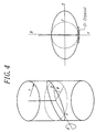
- Figs. 2 and 3 are diagrams explaining a principal method of designing the monochromator embodying the present invention.
- a cylindrical body A made of, for example, copper is first prepared. This cylindrical body A is then cut at a maximum asymmetric angle ⁇ 0 with respect to a plane orthogonal to an center axis of the cylindrical body.
- the maximum asymmetric angle ⁇ 0 means an angle which is 2 to 5 degrees lager than a maximum angle of an asymmetric angel ⁇ between the Bragg plane and a crystal plane.
- an asymmetric factor b representing a change in a ratio of an outgoing X-ray beam to an incident X-ray beam as shown by the following equation (1) is identical with the above mentioned value.
- b sin( ⁇ + ⁇ )/sin( ⁇ - ⁇ ) where ⁇ is an angle of diffraction due to a (111) silicon crystal.
- ⁇ is an angle of diffraction due to a (111) silicon crystal.
- the asymmetric cut surface is shaped along a peripheral surface of an imaginary cylindrical body B having a radius R 0 .
- an azimuth angle around the center axial line of the cylindrical body A is defined by ⁇
- a direction in which a tilt angle of the focusing tilted-surface becomes maximum is defined by ⁇ 0
- the center axial line 1 of the imaginary cylindrical body B (see Fig.
- the above angle ⁇ is referred to as an offset angle, which is required to simultaneously tune, by only the ⁇ -axis rotation, two parameters of the asymmetric angle ⁇ and the radius of curvature R of the asymmetric curved surface.
- the radius of curvature R of the asymmetric cut curved-surface can be calculated as follows:
- the asymmetric angle ⁇ exhibited at the angle ⁇ may be determined as follows:
- the optimum value of the asymmetric angle ⁇ can be obtained by substituting 16.7 for the asymmetric factor b in the above-mentioned equation (1).
- the azimuth angle ⁇ used for obtaining the above ⁇ value on the monochromator can be calculated by the use of the equation (6), and then the radius of curvature R corresponding to this ⁇ value can be obtained by the use of the equation (4).
- the offset angle ⁇ is determined, based on the above-mentioned relationship, in such a manner that the asymmetric angle ⁇ and the radius of curvature R become most suitable for a desired wavelength.
- the monochromator crystal 5 cut at the asymmetric angle ⁇ 0 .
- the monochromator crystal 5 is bonded such that the direction showing the asymmetric angle ⁇ 0 of the crystal is coincided with the azimuth angle ⁇ 0 .
- the axis of the reflecting surface can be coincided with the ⁇ axis, the asymmetric angle ⁇ can be changed in accordance with the equation (6) by the rotation about the ⁇ axis and the radius of curvature R of the focusing curved surface can be changed in accordance with the equation (4). Therefore, a wide wavelength ranged can be covered by only one monochromator crystal. Further, since the monochromator crystal is fixed to the pedestal, a cooling water may be circulated through the pedestal to mitigate the problem of thermal load to a large extent.
- This wavelength range may be set to, for example, 0.87 to 1.9 ⁇ .
- a spacing d 111 is 3.136 ⁇ .
- This ⁇ max value can also be determined as the maximum asymmetric angle ⁇ 0 which is, taking account of design margin, made larger slightly. To this end, for example, the ⁇ 0 value is 19.7.
- the imaginary cylindrical body B used when the reflecting surface is shaped like a cylinder.
- the ⁇ axis is rotated to change the wavelength, and when an amount of the ⁇ axis rotation is increased, the radius of curvature of the reflecting surface of the monochromator becomes larger. Therefore, the minimum radius of the imaginary cylindrical body B obtained when forming the reflecting surface must be R min or less than R min . In this example, the minimum radius is made shorter than R min by 3 m; therefore, R 0 is 38.7 m.
- an average value of ⁇ is 21.8°; therefore, the value of ⁇ may be determined to be 21.8°.
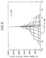
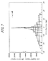
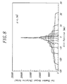
- a monochromator was actually designed and manufactured in accordance with the above-mentioned design conditions, and then performance experiments were carried out. The results will be described below.
- the actual test was carried out for three wavelengths of 1.04, 1.38, and 174 ⁇ which cover a wavelength range required for the heavy atom isomorphism substitution method.
- the respective wavelengths are absorption edges of Au, Cu, Fe.
- Table 3 shows parameters of the monochromator for each of the wavelengths. In actual, the wavelength was first determined by the Bragg plane rotation, and then the focusing was carried out while simultaneously optimizing the asymmetric angle ⁇ and the radius of curvature R by the ⁇ -axis rotation.
- R opt is an ideal radius, and ⁇ represents
- Figs. 6 to 8 reveal that the monochromator embodying the present invention can generate well compressed and focussed beam at respective wavelengths with only one ⁇ -axis rotation just as designed.
Landscapes
- Physics & Mathematics (AREA)
- Spectroscopy & Molecular Physics (AREA)
- Engineering & Computer Science (AREA)
- General Engineering & Computer Science (AREA)
- High Energy & Nuclear Physics (AREA)
- Analysing Materials By The Use Of Radiation (AREA)
Applications Claiming Priority (2)
| Application Number | Priority Date | Filing Date | Title |
|---|---|---|---|
| JP10325189A JP2976029B1 (ja) | 1998-11-16 | 1998-11-16 | モノクロメータ及びその製造方法 |
| JP32518998 | 1998-11-16 |
Publications (2)
| Publication Number | Publication Date |
|---|---|
| EP1001434A2 true EP1001434A2 (fr) | 2000-05-17 |
| EP1001434A3 EP1001434A3 (fr) | 2002-12-18 |
Family
ID=18174014
Family Applications (1)
| Application Number | Title | Priority Date | Filing Date |
|---|---|---|---|
| EP99309083A Withdrawn EP1001434A3 (fr) | 1998-11-16 | 1999-11-16 | Monochromateur et son procédé de fabrication |
Country Status (3)
| Country | Link |
|---|---|
| US (1) | US6229874B1 (fr) |
| EP (1) | EP1001434A3 (fr) |
| JP (1) | JP2976029B1 (fr) |
Cited By (1)
| Publication number | Priority date | Publication date | Assignee | Title |
|---|---|---|---|---|
| EP2328153A3 (fr) * | 2009-11-30 | 2012-02-08 | Canon Kabushiki Kaisha | Monochromateur à rayons x, son procédé de fabrication et spectromètre à rayons x |
Family Cites Families (5)
| Publication number | Priority date | Publication date | Assignee | Title |
|---|---|---|---|---|
| US2853617A (en) * | 1955-01-27 | 1958-09-23 | California Inst Res Found | Focusing crystal for x-rays and method of manufacture |
| NL8501181A (nl) * | 1985-04-24 | 1986-11-17 | Philips Nv | Kristal voor een roentgenanalyse apparaat. |
| NL8801019A (nl) * | 1988-04-20 | 1989-11-16 | Philips Nv | Roentgen spectrometer met dubbel gebogen kristal. |
| US5004319A (en) * | 1988-12-29 | 1991-04-02 | The United States Of America As Represented By The Department Of Energy | Crystal diffraction lens with variable focal length |
| US5923720A (en) * | 1997-06-17 | 1999-07-13 | Molecular Metrology, Inc. | Angle dispersive x-ray spectrometer |
-
1998
- 1998-11-16 JP JP10325189A patent/JP2976029B1/ja not_active Expired - Lifetime
-
1999
- 1999-11-15 US US09/439,283 patent/US6229874B1/en not_active Expired - Fee Related
- 1999-11-16 EP EP99309083A patent/EP1001434A3/fr not_active Withdrawn
Cited By (2)
| Publication number | Priority date | Publication date | Assignee | Title |
|---|---|---|---|---|
| EP2328153A3 (fr) * | 2009-11-30 | 2012-02-08 | Canon Kabushiki Kaisha | Monochromateur à rayons x, son procédé de fabrication et spectromètre à rayons x |
| US8787525B2 (en) | 2009-11-30 | 2014-07-22 | Canon Kabushiki Kaisha | X-ray monochromator, method of manufacturing the same and X-ray spectrometer |
Also Published As
| Publication number | Publication date |
|---|---|
| US6229874B1 (en) | 2001-05-08 |
| EP1001434A3 (fr) | 2002-12-18 |
| JP2000147196A (ja) | 2000-05-26 |
| JP2976029B1 (ja) | 1999-11-10 |
Similar Documents
| Publication | Publication Date | Title |
|---|---|---|
| Dietz et al. | A high flux toroidal grating monochromator for the soft X-ray region | |
| EP2075569B1 (fr) | Dispositif à faisceau de rayons X | |
| EP1234310B1 (fr) | Dispositif optique a double courbure avec plans atomiques a gradient | |
| Eng et al. | Dynamically figured Kirkpatrick Baez x-ray microfocusing optics | |
| US4599741A (en) | System for local X-ray excitation by monochromatic X-rays | |
| EP0635716B1 (fr) | Monochromateur asymétrique à 4 cristaux | |
| US4649557A (en) | X-ray analysis apparatus including a monochromator crystal having crystal lattice surfaces | |
| US4461018A (en) | Diffraction crystal for sagittally focusing x-rays | |
| Ferrer et al. | D2AM, a beamline with a high-intensity point-focusing fixed-exit monochromator for multiwavelength anomalous diffraction experiments | |
| EP0604343A1 (fr) | Méthode de balayage aux rayons X pour rendre une distorsion petite ou constante dans la lithographie de proximité aux rayons X | |
| Follath et al. | Optical design of the ARAMIS-beamlines at SwissFEL | |
| EP1001434A2 (fr) | Monochromateur et son procédé de fabrication | |
| JP2666871B2 (ja) | X線モノクロメータ | |
| US6233096B1 (en) | Pseudo-spherical stepped diffractor constructed under constant step width conditions (multi-stepped monochromator) | |
| Signorato et al. | Performance of the ESRF ID26 beamline reflective optics | |
| JP4710022B2 (ja) | 曲率分布結晶レンズ、曲率分布結晶レンズを有するx線装置及び曲率分布結晶レンズの作製方法 | |
| US6844973B1 (en) | Plane diffraction grating based on surface normal rotation and its application to an optical system | |
| US5047650A (en) | Monochrometer | |
| EP0710857B1 (fr) | Procédé pour augmenter l'indice de réfraction de verre de silice | |
| Schildkamp | Design of a tunable and focusing single crystal monochromator for powerful X-ray sources | |
| JP3440687B2 (ja) | 鏡面修整成形ビームアンテナ | |
| Oestreich et al. | Single-movement fixed-exit channelcut x-ray monochromator based on profiled surfaces | |
| Van Der Hoek et al. | Design, construction and test results of a slitless, high-power, high-resolution double crystal X-ray monochromator for synchrotron radiation | |
| US20020003662A1 (en) | Pseudo-spherical stepped diffractor constructed under constant step width conditions (multi-stepped monochromator) | |
| Smith et al. | Spherical-grating monochromator system with circular-polarization capability for the U5U undulator at Brookhaven |
Legal Events
| Date | Code | Title | Description |
|---|---|---|---|
| PUAI | Public reference made under article 153(3) epc to a published international application that has entered the european phase |
Free format text: ORIGINAL CODE: 0009012 |
|
| AK | Designated contracting states |
Kind code of ref document: A2 Designated state(s): AT BE CH CY DE DK ES FI FR GB GR IE IT LI LU MC NL PT SE |
|
| AX | Request for extension of the european patent |
Free format text: AL;LT;LV;MK;RO;SI |
|
| PUAL | Search report despatched |
Free format text: ORIGINAL CODE: 0009013 |
|
| AK | Designated contracting states |
Kind code of ref document: A3 Designated state(s): AT BE CH CY DE DK ES FI FR GB GR IE IT LI LU MC NL PT SE |
|
| AX | Request for extension of the european patent |
Free format text: AL;LT;LV;MK;RO;SI |
|
| 17P | Request for examination filed |
Effective date: 20030226 |
|
| AKX | Designation fees paid |
Designated state(s): DE FR GB NL |
|
| STAA | Information on the status of an ep patent application or granted ep patent |
Free format text: STATUS: THE APPLICATION IS DEEMED TO BE WITHDRAWN |
|
| 18D | Application deemed to be withdrawn |
Effective date: 20060601 |