EP1001496A2 - Elektrischer Steckverbinder - Google Patents
Elektrischer Steckverbinder Download PDFInfo
- Publication number
- EP1001496A2 EP1001496A2 EP99122590A EP99122590A EP1001496A2 EP 1001496 A2 EP1001496 A2 EP 1001496A2 EP 99122590 A EP99122590 A EP 99122590A EP 99122590 A EP99122590 A EP 99122590A EP 1001496 A2 EP1001496 A2 EP 1001496A2
- Authority
- EP
- European Patent Office
- Prior art keywords
- cavities
- connector
- sealing member
- terminal
- terminals
- Prior art date
- Legal status (The legal status is an assumption and is not a legal conclusion. Google has not performed a legal analysis and makes no representation as to the accuracy of the status listed.)
- Withdrawn
Links
Images

Classifications
-
- H—ELECTRICITY
- H01—ELECTRIC ELEMENTS
- H01R—ELECTRICALLY-CONDUCTIVE CONNECTIONS; STRUCTURAL ASSOCIATIONS OF A PLURALITY OF MUTUALLY-INSULATED ELECTRICAL CONNECTING ELEMENTS; COUPLING DEVICES; CURRENT COLLECTORS
- H01R13/00—Details of coupling devices of the kinds covered by groups H01R12/70 or H01R24/00 - H01R33/00
- H01R13/46—Bases; Cases
- H01R13/52—Dustproof, splashproof, drip-proof, waterproof, or flameproof cases
- H01R13/5205—Sealing means between cable and housing, e.g. grommet
- H01R13/5208—Sealing means between cable and housing, e.g. grommet having at least two cable receiving openings
Definitions
- the present invention relates to an electric connector, in particular a sealed electric connector.
- Electric connectors of the above type are known - for example, from Italian Patent IT 1270371 filed by the present Applicant, and from French Patent FR 2602374 - which comprise an insulating casing defining a number of cavities for housing respective electric terminals connected to respective electric cables; and a sealing member for protection against external agents, and which is normally defined by a mattress made of elastomeric material, connected to the casing on the terminal insertion side into the respective cavities, and having a number of through seats coaxial with the cavities and engaged by the respective electric cables.
- the electric terminals when wiring the connector, the electric terminals, already crimped to the respective electric cables, may be inserted into and withdrawn from the respective cavities several times, e.g. to correct assembly errors; in which case, and particularly when withdrawing the terminals from the respective cavities, any sharp edges or aggressive portions of the terminals, such as the elastic lances engaging the walls of the cavities, may possibly damage the sealing member when fitted through the respective seats in the member, thus resulting in cutting or tearing of the seat edges and so impairing in-service sealing of the connector.
- an electric connector comprising an insulating casing defining a number of cavities for respective electric terminals; and a sealing unit in turn comprising a sealing member connected to said casing, on the side on which said terminals are inserted inside said cavities, and having a number of through seats coaxial with the cavities and engaged by respective electric cables connected to said terminals; characterized in that said sealing unit comprises at least one protection member in sheet form, which is located on one side of said sealing member and has a number of slitted openings coaxial with said cavities and with said seats, and each defined by a number of flexible flaps which are interposed between the respective said terminal and said sealing member during passage of the terminal inside the respective said seat, so as to protect said sealing member from contact with said terminal.
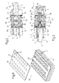
- Number 1 in Figure 1 indicates a sealed electric connector in accordance with the present invention.
- Connector 1 comprises an insulating casing 2 made of plastic material and defining a number of rows of longitudinal cavities 3 having respective axes A parallel to a connection direction B of connector 1 to a complementary connector ( Figures 2 and 3). Cavities 3 are designed to receive respective female electric terminals 4 (only one shown in Figure 1) connected to respective electric cables 5 (only one shown in Figure 1) and retained inside cavities 3 by known primary and secondary retaining means not forming part of the present invention and therefore not described in detail.
- each terminal 4 comprises a substantially cylindrical tubular front contact portion 6 which mates with a corresponding male electric terminal (not shown) of the complementary connector; a rear portion 7 for connection to respective electric cable 5; and an intermediate portion 8 interposed between, and smaller in section than, portions 6 and 7.
- Each terminal 4 is inserted inside respective cavity 3 through a rear opening 9 of the cavity, from which respective electric cable 5 projects in use, and is positioned with contact portion 6 facing a front opening 11 of cavity 3.
- the primary retaining means comprise a retaining seat 15 formed in the lateral wall of respective cavity 3; and an elastic lance 16 projecting outwards from contact portion 6 of terminal 4, substantially in a direction parallel to direction B and towards intermediate portion 8, and which clicks onto seat 15.
- the secondary retaining means comprise a substantially comb-shaped movable member 17 formed separately from casing 2 and which fits onto casing 2 in a direction perpendicular to direction B, and inside a seat 18 intersecting cavities 3.
- movable member 17 comprises a number of arms 19, which cooperate, in pairs and on opposite sides of each row of cavities 3, with intermediate portions 8 of respective terminals 4, to determine correct insertion of terminals 4 inside cavities 3 and prevent withdrawal of the terminals.
- Connector 1 also comprises a sealing unit for protection against external agents and indicated as a whole by 20 in Figure 4.
- Unit 20 comprises a sealing member 21 defined, in the example shown, by a substantially parallelepipedal mattress made of elastomeric material, fitted to casing 2 on the insertion side of terminals 4 inside cavities 3, and having a number of through seats 22 coaxial with cavities 3 and engaged by respective electric cables 5.
- sealing member 21 is fitted inside a rear compartment 23 of casing 2 communicating with cavities 3 through openings 9, and is pressed towards cavities 3 by a grille 24, which clicks onto a lateral wall 25 of compartment 23 and has a number of through holes 26 coaxial with cavities 3 and with seats 22 and which are engaged by respective electric cables 5.
- Sealing member 21 also has a lateral edge defined by a number of - in the example shown, three - superimposed projecting peripheral lips 27, which cooperate with lateral wall 25 of compartment 23.
- Each seat 22 of sealing member 21 has, internally, a number of projecting annular lips 28 - three in the example shown - which cooperate in sealing manner with respective electric cable 5.
- unit 20 also comprises a protection member 30 in sheet form, which is located on one side of sealing member 21 and has a number of slitted openings 31 coaxial with cavities 3 and with seats 22, and each defined by a number of flexible flaps 32 which are interposed between the respective terminal 4 and sealing member 21 during passage of the terminal 4 inside respective seat 22, so as to protect sealing member 21 from contact with terminal 4 ( Figure 3).
- a protection member 30 in sheet form, which is located on one side of sealing member 21 and has a number of slitted openings 31 coaxial with cavities 3 and with seats 22, and each defined by a number of flexible flaps 32 which are interposed between the respective terminal 4 and sealing member 21 during passage of the terminal 4 inside respective seat 22, so as to protect sealing member 21 from contact with terminal 4 ( Figure 3).
- protection member 30 is made of polymer material - in the example shown, mylar - and is interposed between sealing member 21 and openings 9 of cavities 3.
- openings 31 of protection member 30 are each defined by two straight slits 33 intersecting crosswise.
- protection member 30 may be located on the opposite side of sealing member 21 to cavities 3, or two protection members may be provided on either side of sealing member 21.
Landscapes
- Connector Housings Or Holding Contact Members (AREA)
- Coupling Device And Connection With Printed Circuit (AREA)
- Details Of Connecting Devices For Male And Female Coupling (AREA)
Applications Claiming Priority (2)
| Application Number | Priority Date | Filing Date | Title |
|---|---|---|---|
| ITTO980960 | 1998-11-13 | ||
| IT1998TO000960A IT1305180B1 (it) | 1998-11-13 | 1998-11-13 | Connettore elettrico. |
Publications (2)
| Publication Number | Publication Date |
|---|---|
| EP1001496A2 true EP1001496A2 (de) | 2000-05-17 |
| EP1001496A3 EP1001496A3 (de) | 2000-09-27 |
Family
ID=11417181
Family Applications (1)
| Application Number | Title | Priority Date | Filing Date |
|---|---|---|---|
| EP99122590A Withdrawn EP1001496A3 (de) | 1998-11-13 | 1999-11-12 | Elektrischer Steckverbinder |
Country Status (3)
| Country | Link |
|---|---|
| US (1) | US6174200B1 (de) |
| EP (1) | EP1001496A3 (de) |
| IT (1) | IT1305180B1 (de) |
Cited By (7)
| Publication number | Priority date | Publication date | Assignee | Title |
|---|---|---|---|---|
| WO2008012099A1 (en) * | 2006-07-27 | 2008-01-31 | Fci | Electrical connector and method of manufacturing |
| WO2012071079A1 (en) * | 2010-11-22 | 2012-05-31 | Andrew Llc | Laser weld coaxial connector and interconnection method |
| WO2012071080A1 (en) * | 2010-11-22 | 2012-05-31 | Andrew Llc | Friction weld coaxial connector and interconnection method |
| US8479383B2 (en) | 2010-11-22 | 2013-07-09 | Andrew Llc | Friction weld coaxial connector and interconnection method |
| US10665967B2 (en) | 2010-11-22 | 2020-05-26 | Commscope Technologies Llc | Ultrasonic weld interconnection coaxial connector and interconnection with coaxial cable |
| CN113169477A (zh) * | 2018-08-17 | 2021-07-23 | 大众汽车股份公司 | 插接连接器 |
| US11437766B2 (en) | 2010-11-22 | 2022-09-06 | Commscope Technologies Llc | Connector and coaxial cable with molecular bond interconnection |
Families Citing this family (3)
| Publication number | Priority date | Publication date | Assignee | Title |
|---|---|---|---|---|
| US6752668B2 (en) | 2002-08-14 | 2004-06-22 | Konnektech, Ltd. | Electrical connector |
| JP5203094B2 (ja) * | 2008-04-03 | 2013-06-05 | 矢崎総業株式会社 | コネクタ用パッキン構造 |
| US9728926B2 (en) | 2010-11-22 | 2017-08-08 | Commscope Technologies Llc | Method and apparatus for radial ultrasonic welding interconnected coaxial connector |
Family Cites Families (8)
| Publication number | Priority date | Publication date | Assignee | Title |
|---|---|---|---|---|
| DE2008342A1 (de) | 1970-02-23 | 1971-09-02 | Amphenol Tuchel Elect | Mehrpolige Steckvorrichtung fur elek trische Leitungsverbindungen |
| FR2602374A1 (fr) | 1986-08-01 | 1988-02-05 | Drogo Pierre | Connecteur electrique |
| US5360945A (en) * | 1991-05-01 | 1994-11-01 | Raychem Corporation | Cable seal |
| US5090927A (en) | 1991-06-27 | 1992-02-25 | At&T Bell Laboratories | Connectors including lead alignment strips |
| US5588856A (en) * | 1991-09-18 | 1996-12-31 | Raychem Corporation | Sealing member and methods of sealing |
| IT1270371B (it) | 1993-05-21 | 1997-05-05 | Framatome Connectors Italia | Connettore elettrico |
| JP4163263B2 (ja) * | 1995-04-06 | 2008-10-08 | 矢崎総業株式会社 | 防水コネクタ |
| AU6660698A (en) * | 1997-02-20 | 1998-09-09 | Whitaker Corporation, The | Sealed electrical conductor assembly |
-
1998
- 1998-11-13 IT IT1998TO000960A patent/IT1305180B1/it active
-
1999
- 1999-11-12 US US09/438,230 patent/US6174200B1/en not_active Expired - Fee Related
- 1999-11-12 EP EP99122590A patent/EP1001496A3/de not_active Withdrawn
Cited By (22)
| Publication number | Priority date | Publication date | Assignee | Title |
|---|---|---|---|---|
| WO2008012099A1 (en) * | 2006-07-27 | 2008-01-31 | Fci | Electrical connector and method of manufacturing |
| US10819046B2 (en) | 2010-11-22 | 2020-10-27 | Commscope Technologies Llc | Ultrasonic weld interconnection coaxial connector and interconnection with coaxial cable |
| US11437766B2 (en) | 2010-11-22 | 2022-09-06 | Commscope Technologies Llc | Connector and coaxial cable with molecular bond interconnection |
| US8302296B2 (en) | 2010-11-22 | 2012-11-06 | Andrew, Llc | Friction weld coaxial connector and interconnection method |
| US8479383B2 (en) | 2010-11-22 | 2013-07-09 | Andrew Llc | Friction weld coaxial connector and interconnection method |
| US8556655B2 (en) | 2010-11-22 | 2013-10-15 | Andrew Llc | Friction weld coaxial connector |
| US8826525B2 (en) | 2010-11-22 | 2014-09-09 | Andrew Llc | Laser weld coaxial connector and interconnection method |
| US8887379B2 (en) | 2010-11-22 | 2014-11-18 | Andrew Llc | Friction weld coaxial connector interconnection support |
| US10431909B2 (en) | 2010-11-22 | 2019-10-01 | Commscope Technologies Llc | Laser weld coaxial connector and interconnection method |
| US10665967B2 (en) | 2010-11-22 | 2020-05-26 | Commscope Technologies Llc | Ultrasonic weld interconnection coaxial connector and interconnection with coaxial cable |
| WO2012071079A1 (en) * | 2010-11-22 | 2012-05-31 | Andrew Llc | Laser weld coaxial connector and interconnection method |
| WO2012071080A1 (en) * | 2010-11-22 | 2012-05-31 | Andrew Llc | Friction weld coaxial connector and interconnection method |
| US11437767B2 (en) | 2010-11-22 | 2022-09-06 | Commscope Technologies Llc | Connector and coaxial cable with molecular bond interconnection |
| US12113317B2 (en) | 2010-11-22 | 2024-10-08 | Outdoor Wireless Networks LLC | Connector and coaxial cable with molecular bond interconnection |
| US11462843B2 (en) | 2010-11-22 | 2022-10-04 | Commscope Technologies Llc | Ultrasonic weld interconnection coaxial connector and interconnection with coaxial cable |
| US12100925B2 (en) | 2010-11-22 | 2024-09-24 | Outdoor Wireless Networks LLC | Ultrasonic weld interconnection coaxial connector and interconnection with coaxial cable |
| US11735874B2 (en) | 2010-11-22 | 2023-08-22 | Commscope Technologies Llc | Connector and coaxial cable with molecular bond interconnection |
| US11757212B2 (en) | 2010-11-22 | 2023-09-12 | Commscope Technologies Llc | Ultrasonic weld interconnection coaxial connector and interconnection with coaxial cable |
| CN113169477B (zh) * | 2018-08-17 | 2023-09-05 | 大众汽车股份公司 | 插接连接器 |
| US11539159B2 (en) | 2018-08-17 | 2022-12-27 | Volkswagen Aktiengesellschaft | Plug connector |
| CN113169477A (zh) * | 2018-08-17 | 2021-07-23 | 大众汽车股份公司 | 插接连接器 |
| EP3837740B1 (de) * | 2018-08-17 | 2024-10-09 | Volkswagen Aktiengesellschaft | Steckverbinder |
Also Published As
| Publication number | Publication date |
|---|---|
| ITTO980960A1 (it) | 2000-05-13 |
| US6174200B1 (en) | 2001-01-16 |
| EP1001496A3 (de) | 2000-09-27 |
| IT1305180B1 (it) | 2001-04-10 |
Similar Documents
| Publication | Publication Date | Title |
|---|---|---|
| EP0895312B1 (de) | Elektrischer Verbinder mit Kontaktlagessicherungsvorrichtung | |
| EP0306635B1 (de) | Elektrischer Steckverbinder | |
| EP0625807B1 (de) | Elektrischer Verbinder | |
| EP1962390B1 (de) | Verbinder und Verbinderanordnung | |
| EP1193808B1 (de) | Elektrischer Verbinder | |
| EP1104051B1 (de) | Verbinder | |
| EP1137118B1 (de) | Verbinder mit einem Port zum Einführen eines Kontaktstiftes eines Leitungstestwerkzeugs | |
| US7044808B1 (en) | Connector assembly with terminal position assurance device | |
| US7581969B2 (en) | Connector with auxiliary housing having inverted insertion preventing portion | |
| WO2015049691A1 (en) | Electrical connector with sealing structure | |
| US6174200B1 (en) | Electric connector | |
| EP0125786A2 (de) | Elektrischer Verbindungszusammenbau | |
| US6059602A (en) | Shroud for electrical connector | |
| WO2015134447A1 (en) | Electrical connector assembly | |
| US6247966B1 (en) | Electrical connector with exposed molded latches | |
| US20120009809A1 (en) | Connector | |
| EP0955695A2 (de) | Elektrischer Verbinder mit Kontaktverriegelung | |
| CN102544880A (zh) | 连接器 | |
| JP6898220B2 (ja) | コネクタハウジング | |
| EP0510583B2 (de) | Elektrischer Steckverbinder | |
| EP1231676B1 (de) | Verbinder | |
| EP0147075B1 (de) | Stecker mit Kontaktverriegelungselementen | |
| US5820410A (en) | Electric connector | |
| EP0581320A1 (de) | Elektrischer Verbinder | |
| EP0791985A1 (de) | Abgedichteter elektischer Verbinder |
Legal Events
| Date | Code | Title | Description |
|---|---|---|---|
| PUAI | Public reference made under article 153(3) epc to a published international application that has entered the european phase |
Free format text: ORIGINAL CODE: 0009012 |
|
| AK | Designated contracting states |
Kind code of ref document: A2 Designated state(s): AT BE CH CY DE DK ES FI FR GB GR IE IT LI LU MC NL PT SE |
|
| AX | Request for extension of the european patent |
Free format text: AL;LT;LV;MK;RO;SI |
|
| PUAL | Search report despatched |
Free format text: ORIGINAL CODE: 0009013 |
|
| AK | Designated contracting states |
Kind code of ref document: A3 Designated state(s): AT BE CH CY DE DK ES FI FR GB GR IE IT LI LU MC NL PT SE |
|
| AX | Request for extension of the european patent |
Free format text: AL;LT;LV;MK;RO;SI |
|
| RAP1 | Party data changed (applicant data changed or rights of an application transferred) |
Owner name: FRAMATOME CONNECTORS INTERNATIONAL S.A. |
|
| 17P | Request for examination filed |
Effective date: 20010226 |
|
| AKX | Designation fees paid |
Free format text: AT BE CH CY DE DK ES FI FR GB GR IE IT LI LU MC NL PT SE |
|
| RAP1 | Party data changed (applicant data changed or rights of an application transferred) |
Owner name: FCI |
|
| STAA | Information on the status of an ep patent application or granted ep patent |
Free format text: STATUS: THE APPLICATION IS DEEMED TO BE WITHDRAWN |
|
| 18D | Application deemed to be withdrawn |
Effective date: 20040602 |