EP1001508A2 - Frein électromagnétique avec deux disques indépendants - Google Patents
Frein électromagnétique avec deux disques indépendants Download PDFInfo
- Publication number
- EP1001508A2 EP1001508A2 EP99121978A EP99121978A EP1001508A2 EP 1001508 A2 EP1001508 A2 EP 1001508A2 EP 99121978 A EP99121978 A EP 99121978A EP 99121978 A EP99121978 A EP 99121978A EP 1001508 A2 EP1001508 A2 EP 1001508A2
- Authority
- EP
- European Patent Office
- Prior art keywords
- disks
- brake
- sleeve
- brake according
- braking
- Prior art date
- Legal status (The legal status is an assumption and is not a legal conclusion. Google has not performed a legal analysis and makes no representation as to the accuracy of the status listed.)
- Withdrawn
Links
Images


Classifications
-
- H—ELECTRICITY
- H02—GENERATION; CONVERSION OR DISTRIBUTION OF ELECTRIC POWER
- H02K—DYNAMO-ELECTRIC MACHINES
- H02K7/00—Arrangements for handling mechanical energy structurally associated with dynamo-electric machines, e.g. structural association with mechanical driving motors or auxiliary dynamo-electric machines
- H02K7/10—Structural association with clutches, brakes, gears, pulleys or mechanical starters
- H02K7/102—Structural association with clutches, brakes, gears, pulleys or mechanical starters with friction brakes
- H02K7/1021—Magnetically influenced friction brakes
- H02K7/1023—Magnetically influenced friction brakes using electromagnets
- H02K7/1025—Magnetically influenced friction brakes using electromagnets using axial electromagnets with generally annular air gap
-
- F—MECHANICAL ENGINEERING; LIGHTING; HEATING; WEAPONS; BLASTING
- F16—ENGINEERING ELEMENTS AND UNITS; GENERAL MEASURES FOR PRODUCING AND MAINTAINING EFFECTIVE FUNCTIONING OF MACHINES OR INSTALLATIONS; THERMAL INSULATION IN GENERAL
- F16D—COUPLINGS FOR TRANSMITTING ROTATION; CLUTCHES; BRAKES
- F16D55/00—Brakes with substantially-radial braking surfaces pressed together in axial direction, e.g. disc brakes
- F16D55/24—Brakes with substantially-radial braking surfaces pressed together in axial direction, e.g. disc brakes with a plurality of axially-movable discs, lamellae, or pads, pressed from one side towards an axially-located member
-
- F—MECHANICAL ENGINEERING; LIGHTING; HEATING; WEAPONS; BLASTING
- F16—ENGINEERING ELEMENTS AND UNITS; GENERAL MEASURES FOR PRODUCING AND MAINTAINING EFFECTIVE FUNCTIONING OF MACHINES OR INSTALLATIONS; THERMAL INSULATION IN GENERAL
- F16D—COUPLINGS FOR TRANSMITTING ROTATION; CLUTCHES; BRAKES
- F16D59/00—Self-acting brakes, e.g. coming into operation at a predetermined speed
- F16D59/02—Self-acting brakes, e.g. coming into operation at a predetermined speed spring-loaded and adapted to be released by mechanical, fluid, or electromagnetic means
-
- F—MECHANICAL ENGINEERING; LIGHTING; HEATING; WEAPONS; BLASTING
- F16—ENGINEERING ELEMENTS AND UNITS; GENERAL MEASURES FOR PRODUCING AND MAINTAINING EFFECTIVE FUNCTIONING OF MACHINES OR INSTALLATIONS; THERMAL INSULATION IN GENERAL
- F16D—COUPLINGS FOR TRANSMITTING ROTATION; CLUTCHES; BRAKES
- F16D2121/00—Type of actuator operation force
- F16D2121/18—Electric or magnetic
- F16D2121/20—Electric or magnetic using electromagnets
- F16D2121/22—Electric or magnetic using electromagnets for releasing a normally applied brake
-
- F—MECHANICAL ENGINEERING; LIGHTING; HEATING; WEAPONS; BLASTING
- F16—ENGINEERING ELEMENTS AND UNITS; GENERAL MEASURES FOR PRODUCING AND MAINTAINING EFFECTIVE FUNCTIONING OF MACHINES OR INSTALLATIONS; THERMAL INSULATION IN GENERAL
- F16D—COUPLINGS FOR TRANSMITTING ROTATION; CLUTCHES; BRAKES
- F16D2123/00—Multiple operation forces
-
- F—MECHANICAL ENGINEERING; LIGHTING; HEATING; WEAPONS; BLASTING
- F16—ENGINEERING ELEMENTS AND UNITS; GENERAL MEASURES FOR PRODUCING AND MAINTAINING EFFECTIVE FUNCTIONING OF MACHINES OR INSTALLATIONS; THERMAL INSULATION IN GENERAL
- F16D—COUPLINGS FOR TRANSMITTING ROTATION; CLUTCHES; BRAKES
- F16D2127/00—Auxiliary mechanisms
- F16D2127/02—Release mechanisms
- F16D2127/04—Release mechanisms for manual operation
Definitions
- the present invention relates to an electromagnetic brake with two independent front disks.
- a brake The purpose of a brake is to "brake" the torque of a manufacturing machine or power-using machine.
- Conventional electromagnetic brakes operate by means of the pressure of springs which act when there is no power.
- brakes are therefore fail-safe devices which lock the driven shaft when they are in an inactive position and release it when they are actuated electrically: locking occurs by means of a system of springs, whereas disengagement is achieved by supplying power to a coil which generates a contrasting magnetic field suitable to overcome the action of the springs.
- the brakes that are normally in use have an adequate operating principle, they usually have a single braking disk or sometimes a plurality of disks which however do not act independently of each other; conventional brakes, therefore, are often not completely compliant with applicable safety standards related to the elevator sector.
- Applicable standards in fact prescribe at least two mechanical braking elements, for obvious safety reasons, and also prescribe that it must be possible to slow the system if only one of said elements remains active.
- the aim of the present invention is therefore to provide a single braking unit which, by combining two conventional braking units which are appropriately separated from each other, makes the system suitable for use in elevators in compliance with the corresponding standards applicable to the sector.
- an object of the present invention is to provide an electromagnetic brake with two independent front disks which is simple, relatively easy to provide in practice, safe in use, effective in operation and has a relatively low cost.
- an electromagnetic brake with two independent front disks characterized in that it comprises a main assembly which accommodates two separate coils between which a spacer made of non-magnetic material is arranged, said coils being adapted to act independently on two moving cores for pressing against the respective disks.
- the reference sign I designates an electromagnetic brake with two independent front disks according to the present invention.
- the brake I comprises a main assembly II which accommodates two separate coils 19a, 19b between which a spacer 4 made of non-magnetic material is arranged: the coils act independently on two moving cores 5a, 5b for pressing against two respective disks 6a, 6b.
- the brake comprises a flange 7 for fixing to a motor 8 provided with a shaft 9 on which a slotted sleeve 12 is keyed by means of a key 10 and a ring 11; the slotted hubs of the disks 6a, 6b are fitted on the sleeve 12 so that they can slide longitudinally but cannot rotate, and both faces of the disks are covered with friction material 13.
- a corresponding complementary flange 17 is fixed in front of the flange 7 by means of a plurality of stud bolts 14 which are arranged perimetrically and by means of centering bushes 15, nuts and lock nuts 16.
- the fixed main assembly II is fitted between the flange 7 and the complementary flange 17 and is constituted by two coil bodies 18a, 18b within which the two coils 19a, 19b are arranged.
- the coil bodies 18a, 18b are mutually separated by the spacer 4, which is peripherally crossed by the stud bolts 14 and is rigidly coupled thereon by means of nuts and lock nuts.
- the two flat moving cores 5a, 5b are fitted in the two compartments formed between the flange, the central assembly and the complementary flange so that they can slide longitudinally but cannot rotate: sets of compression springs 22a, 22b are mounted in respective sets of seats 21a, 21b which are formed in the coil bodies and are open toward the cores 5a, 5b; the springs are adapted to press the moving cores outward in order to clamp the disks between the movable cores 5a, 5b, the flange 7 and the complementary flange 17: the seats 21 continue with threaded holes for corresponding screws 23 which keep the assembly of the components that constitute the bodies of the two coils 3a, 3b joined to the spacer 4.
- Annular seats 24 for corresponding sealing rings are formed in the bushes 15; such rings are adapted to avoid vibrations during the sliding of the moving cores 5a, 5b, whereas front annular seats 25a, 25b for similar noise damping rings of the type known as O-ring and made of a material such as rubber are formed in the cores 5a, 5b; annular slots 26a, 26b are also formed at the slotted hubs of the disks 6a, 6b in order to accommodate rings of the O-ring type which are adapted to reduce vibration and noise.
- the supply of power to the coils attracts the moving cores toward the central assembly in order to allow the shaft to rotate: by disconnecting the coils from the power supply, the two disks, clamped by the compression springs between the moving cores, the flange and the complementary flange, brake the shaft.
- the sliding blocks 20a, 20b are respectively constituted by a pad 3a, 3b made of antifriction material, by an elastic element 2a, 2b which can be made of spring steel, rubber or other material, and by a registration element 1a, 1b which ensures separation of the respective disk 6a, 6b from the braking plane when the effect of the springs 22a, 22b ceases.
- the reference numeral 27 generally designates an assembly for the manual release of the disks, which comprises a substantially semicircular or horseshoe-shaped bracket 27a which is arranged so as to straddle the main body and has, at its centerline, a lever 28 for manual actuation at right angles to its plane of arrangement (arrow A):
- the bracket 27a has, at its two S-shaped ends, two diametrically mutually opposite holes 30 for articulation to two corresponding pivots which are inserted in the moving core 5b so as to be diametrically aligned;
- the ends 27b of the bracket are provided with two pivots 31 for articulation to one of the ends of respective links 32, the other ends of which are articulated to two diametrical pivots 33 of the other moving core 6b: actuation in the direction of the arrow A of the lever 28 is adapted to produce a relative mutual approach of the two moving cores and therefore to release the brake.
- the ends 27b of the bracket have a further pair of pivots 34 to which it is possible to articulate the links 32 in order to achieve release of the brake when the lever 28 is actuated in the opposite direction with respect to the arrow A.
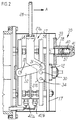
- the reference numeral 35 generally designates an assembly for manually actuating the shaft: the slotted sleeve 12 protrudes at the plane of the outer face of the complementary flange 17; a pivot 37 is fixed laterally with respect to the sleeve on the complementary flange 17, and a hub 38 is fitted thereon so that it can slide axially, a gear 39 being rigidly coupled to the hub 38.
- the gear 39 moves, in contrast with elastic means 40 constituted by a helical compression spring which is interposed between the end face of the hub 38 and the pivot 37, from a position in which it is spaced from the sleeve, as shown in the figure, to a position for meshing with it: the hub 38 has means 41 for interlocking front coupling for the end of a crank which can be actuated manually.
- elastic means 40 constituted by a helical compression spring which is interposed between the end face of the hub 38 and the pivot 37, from a position in which it is spaced from the sleeve, as shown in the figure, to a position for meshing with it: the hub 38 has means 41 for interlocking front coupling for the end of a crank which can be actuated manually.
- Figure 2 illustrates the two independent cable clamps 42a, 42b for supplying the coils 19a, 19b.
- a microswitch 43 which is connected, by means of a bracket 44, to the complementary flange 17 and in which a probe 45 is meant to detect the presence of the gear 39 and notify the control panel that the gear 39 is disengaged from the sleeve 12.
- the moving core 5a may also support, by means of a bracket 46, a microswitch 47 in which the probe is constituted by an elongated screw 48 on which a stroke adjustment nut 49 is screwed.
- the probe 48 is fixed to the core 5b and is adapted to detect the approach of the coils 5a, 5b in order to notify the control panel that the brake is open.
- an electromagnetic brake with two independent front disks is provided in which the disks are independent from the electrical point of view as well, in order to allow to check the efficiency of the braking action of the disks, considered individually; the brake also provides for easy release, suitable accessories for performing manual actuation, and suitable elements for producing safety-related signals.
Landscapes
- Engineering & Computer Science (AREA)
- General Engineering & Computer Science (AREA)
- Physics & Mathematics (AREA)
- Electromagnetism (AREA)
- Mechanical Engineering (AREA)
- Power Engineering (AREA)
- Braking Arrangements (AREA)
Applications Claiming Priority (2)
| Application Number | Priority Date | Filing Date | Title |
|---|---|---|---|
| IT1998BO000635A IT1303970B1 (it) | 1998-11-16 | 1998-11-16 | Freno elettromagnetico a due dischi frontali indipendenti . |
| ITBO980635 | 1998-11-16 |
Publications (2)
| Publication Number | Publication Date |
|---|---|
| EP1001508A2 true EP1001508A2 (fr) | 2000-05-17 |
| EP1001508A3 EP1001508A3 (fr) | 2001-08-22 |
Family
ID=11343505
Family Applications (1)
| Application Number | Title | Priority Date | Filing Date |
|---|---|---|---|
| EP99121978A Withdrawn EP1001508A3 (fr) | 1998-11-16 | 1999-11-10 | Frein électromagnétique avec deux disques indépendants |
Country Status (2)
| Country | Link |
|---|---|
| EP (1) | EP1001508A3 (fr) |
| IT (1) | IT1303970B1 (fr) |
Cited By (9)
| Publication number | Priority date | Publication date | Assignee | Title |
|---|---|---|---|---|
| ES2259865A1 (es) * | 2004-01-26 | 2006-10-16 | Nork 2, S.L. | Freno de seguridad para ascensores. |
| WO2008043655A1 (fr) * | 2006-10-13 | 2008-04-17 | Deere & Company | Frein de blocage pour bloquer par rapport à un boîtier au moins un élément monté à rotation |
| JP2011169385A (ja) * | 2010-02-17 | 2011-09-01 | Sinfonia Technology Co Ltd | 電磁ブレーキ |
| DE102010049744A1 (de) * | 2010-10-29 | 2012-05-03 | Sew-Eurodrive Gmbh & Co. Kg | Bremse |
| US20180017119A1 (en) * | 2014-12-16 | 2018-01-18 | Sew-Eurodrive Gmbh & Co. Kg | Electromagnetically actuable brake device |
| DE102019109654B3 (de) | 2019-04-11 | 2020-01-23 | Kendrion (Villingen) Gmbh | Betätigungseinrichtung sowie elektromagnetische Federdruck-Zweikreisbremse |
| CN111448402A (zh) * | 2017-12-06 | 2020-07-24 | 华纳电气科技有限公司 | 具有用于密封电枢和电磁体之间的接合面的构件的旋转联接装置 |
| EP3760892A1 (fr) * | 2019-07-04 | 2021-01-06 | I&W Engineeering AG | Frein à disques multiples pour dispositif d'entraînement de véhicule |
| JP7249727B1 (ja) | 2022-01-12 | 2023-03-31 | 台達電子工業股▲ふん▼有限公司 | 回転モータのブレーキ装置 |
Family Cites Families (5)
| Publication number | Priority date | Publication date | Assignee | Title |
|---|---|---|---|---|
| US4509620A (en) * | 1982-03-08 | 1985-04-09 | Dresser Industries, Inc. | Hoist or the like |
| JPH0735829B2 (ja) * | 1989-08-18 | 1995-04-19 | 株式会社日立製作所 | エレベータ |
| DE4117095C2 (de) * | 1991-02-21 | 1997-07-10 | Klaue Hermann | Elektrisch zugespannte Vollbelagscheibenbremse, insbesondere für Kraftfahrzeuge |
| US5685398A (en) * | 1996-06-28 | 1997-11-11 | Rexnord Corporation | Fast response adjustable brake |
| DE19737485C1 (de) * | 1997-08-28 | 1999-06-17 | Stromag Ag | Elektromagnetisch betätigbare Bremse und Mehrfachbremsaggregat |
-
1998
- 1998-11-16 IT IT1998BO000635A patent/IT1303970B1/it active
-
1999
- 1999-11-10 EP EP99121978A patent/EP1001508A3/fr not_active Withdrawn
Cited By (19)
| Publication number | Priority date | Publication date | Assignee | Title |
|---|---|---|---|---|
| ES2259865A1 (es) * | 2004-01-26 | 2006-10-16 | Nork 2, S.L. | Freno de seguridad para ascensores. |
| ES2259865B2 (es) * | 2004-01-26 | 2007-12-16 | Nork 2, S.L. | Freno de seguridad para ascensores. |
| WO2008043655A1 (fr) * | 2006-10-13 | 2008-04-17 | Deere & Company | Frein de blocage pour bloquer par rapport à un boîtier au moins un élément monté à rotation |
| EA013959B1 (ru) * | 2006-10-13 | 2010-08-30 | Дир Энд Компани | Фиксирующий тормоз для фиксации по меньшей мере одного установленного с возможностью вращения элемента относительно корпуса |
| JP2011169385A (ja) * | 2010-02-17 | 2011-09-01 | Sinfonia Technology Co Ltd | 電磁ブレーキ |
| DE102010049744B4 (de) * | 2010-10-29 | 2021-04-29 | Sew-Eurodrive Gmbh & Co Kg | Bremse |
| DE102010049744A1 (de) * | 2010-10-29 | 2012-05-03 | Sew-Eurodrive Gmbh & Co. Kg | Bremse |
| US11549562B2 (en) | 2014-12-16 | 2023-01-10 | Sew-Eurodrive Gmbh & Co. Kg | Electromagnetically actuable brake device |
| US10914354B2 (en) * | 2014-12-16 | 2021-02-09 | Sew-Eurodrive Gmbh & Co. Kg | Electromagnetically actuable brake device |
| US20180017119A1 (en) * | 2014-12-16 | 2018-01-18 | Sew-Eurodrive Gmbh & Co. Kg | Electromagnetically actuable brake device |
| CN111448402A (zh) * | 2017-12-06 | 2020-07-24 | 华纳电气科技有限公司 | 具有用于密封电枢和电磁体之间的接合面的构件的旋转联接装置 |
| CN111448402B (zh) * | 2017-12-06 | 2021-08-31 | 华纳电气科技有限公司 | 具有用于密封电枢和电磁体之间的接合面的构件的旋转联接装置 |
| CN111810561A (zh) * | 2019-04-11 | 2020-10-23 | 肯德隆(菲林根)有限公司 | 操纵装置以及电磁的弹簧压力双回路制动器 |
| DE102019109654B3 (de) | 2019-04-11 | 2020-01-23 | Kendrion (Villingen) Gmbh | Betätigungseinrichtung sowie elektromagnetische Federdruck-Zweikreisbremse |
| EP3760892A1 (fr) * | 2019-07-04 | 2021-01-06 | I&W Engineeering AG | Frein à disques multiples pour dispositif d'entraînement de véhicule |
| US11365773B2 (en) | 2019-07-04 | 2022-06-21 | I&W Engineering AG | Multi-disc brake for a vehicle drive, and a vehicle drive |
| JP7249727B1 (ja) | 2022-01-12 | 2023-03-31 | 台達電子工業股▲ふん▼有限公司 | 回転モータのブレーキ装置 |
| JP2023102739A (ja) * | 2022-01-12 | 2023-07-25 | 台達電子工業股▲ふん▼有限公司 | 回転モータのブレーキ装置 |
| US12188531B2 (en) | 2022-01-12 | 2025-01-07 | Delta Electronics, Inc. | Brake device of rotating motor |
Also Published As
| Publication number | Publication date |
|---|---|
| ITBO980635A0 (it) | 1998-11-16 |
| ITBO980635A1 (it) | 2000-05-16 |
| IT1303970B1 (it) | 2001-03-01 |
| EP1001508A3 (fr) | 2001-08-22 |
Similar Documents
| Publication | Publication Date | Title |
|---|---|---|
| US6202804B1 (en) | Electromagnetically releasable friction safety brake | |
| KR0165546B1 (ko) | 승강기용 안전 디스크브레이크 | |
| EP1001508A2 (fr) | Frein électromagnétique avec deux disques indépendants | |
| US7958977B2 (en) | Segment brake | |
| CZ304178B6 (cs) | Seriditelná magnetická spojka s nastavitelnými vzduchovými mezerami | |
| US7714685B2 (en) | Electromagnetically operated unit, in particular a clutch, brake and/or lock | |
| JP5573217B2 (ja) | 電磁ブレーキ | |
| CN214063623U (zh) | 电磁刹车器及车辆 | |
| GB2026110A (en) | Electromagnetically releasable spring-actuated brake | |
| US20060151254A1 (en) | Elevator brake | |
| EP1374368B1 (fr) | Combinaison accouplement et frein | |
| US4362227A (en) | Clutches and brakes | |
| US3878922A (en) | Brake structure | |
| US20060169550A1 (en) | Electromagnetic brake assembly | |
| US2586518A (en) | Mechanical aircraft brake | |
| CN112178076A (zh) | 电磁刹车器及车辆 | |
| JP4837639B2 (ja) | ブレーキ装置 | |
| KR200342425Y1 (ko) | 엘리베이터용 전자브레이크의 전자석부재 | |
| US20060065794A1 (en) | Holding device | |
| CA2472036A1 (fr) | Frein d'ascenseur | |
| GB2032548A (en) | Electromagnetically releasable spring-actuated segmented disc brake | |
| CN219549432U (zh) | 一种方便检修的制动器 | |
| KR100502703B1 (ko) | 전자기적해제가가능한마찰안전브레이크 | |
| CN215444834U (zh) | 复合控制式制动器 | |
| CN224150047U (zh) | 一种电磁制动器 |
Legal Events
| Date | Code | Title | Description |
|---|---|---|---|
| PUAI | Public reference made under article 153(3) epc to a published international application that has entered the european phase |
Free format text: ORIGINAL CODE: 0009012 |
|
| AK | Designated contracting states |
Kind code of ref document: A2 Designated state(s): AT BE CH CY DE DK ES FI FR GB GR IE IT LI LU MC NL PT SE |
|
| AX | Request for extension of the european patent |
Free format text: AL;LT;LV;MK;RO;SI |
|
| PUAL | Search report despatched |
Free format text: ORIGINAL CODE: 0009013 |
|
| AK | Designated contracting states |
Kind code of ref document: A3 Designated state(s): AT BE CH CY DE DK ES FI FR GB GR IE IT LI LU MC NL PT SE |
|
| AX | Request for extension of the european patent |
Free format text: AL;LT;LV;MK;RO;SI |
|
| RIC1 | Information provided on ipc code assigned before grant |
Free format text: 7H 02K 7/102 A, 7F 16D 65/34 B, 7F 16D 59/02 B, 7F 16D 55/24 B |
|
| 17P | Request for examination filed |
Effective date: 20020211 |
|
| AKX | Designation fees paid |
Free format text: AT BE CH CY DE DK ES FI FR GB GR IE IT LI LU MC NL PT SE |
|
| RAP1 | Party data changed (applicant data changed or rights of an application transferred) |
Owner name: ALBERTO SASSI S.P.A |
|
| 17Q | First examination report despatched |
Effective date: 20071220 |
|
| STAA | Information on the status of an ep patent application or granted ep patent |
Free format text: STATUS: THE APPLICATION IS DEEMED TO BE WITHDRAWN |
|
| 18D | Application deemed to be withdrawn |
Effective date: 20080503 |