EP1001539A2 - Méthode de conversion, méthode de restauration, dispositif de conversion, et dispositif de restauration - Google Patents
Méthode de conversion, méthode de restauration, dispositif de conversion, et dispositif de restauration Download PDFInfo
- Publication number
- EP1001539A2 EP1001539A2 EP99120053A EP99120053A EP1001539A2 EP 1001539 A2 EP1001539 A2 EP 1001539A2 EP 99120053 A EP99120053 A EP 99120053A EP 99120053 A EP99120053 A EP 99120053A EP 1001539 A2 EP1001539 A2 EP 1001539A2
- Authority
- EP
- European Patent Office
- Prior art keywords
- subblocks
- information
- original
- inverted
- blocks
- Prior art date
- Legal status (The legal status is an assumption and is not a legal conclusion. Google has not performed a legal analysis and makes no representation as to the accuracy of the status listed.)
- Ceased
Links
Images


Classifications
-
- H—ELECTRICITY
- H03—ELECTRONIC CIRCUITRY
- H03M—CODING; DECODING; CODE CONVERSION IN GENERAL
- H03M5/00—Conversion of the form of the representation of individual digits
- H03M5/02—Conversion to or from representation by pulses
- H03M5/04—Conversion to or from representation by pulses the pulses having two levels
- H03M5/14—Code representation, e.g. transition, for a given bit cell depending on the information in one or more adjacent bit cells, e.g. delay modulation code, double density code
Definitions
- the present invention relates to a conversion method employed to convert sequentially information blocks, each of which is extracted sequentially from information sequence and acts as a conversion unit, into code blocks. More particularly, the present invention relates to a conversion method and a conversion device which are capable of converting the information blocks into the code blocks through simple procedures, while taking account of suppression of a direct current component.
- the present invention also relates to a restoration method and a restoration device which are optimal to restore the code blocks, which are converted by using the above conversion method, to original information blocks.
- the present invention has been made in light of the above circumstances and it is an object of the present invention to provide a conversion method and a conversion device which are capable of converting information blocks into code blocks through simple procedures, while taking account of suppression of a direct current component, by dividing information blocks, each of which is extracted sequentially from information sequence and acts as a conversion unit, into a plurality of original subblocks, then generating inverted subblocks containing inverted information, which are obtained by inverting all original information allocated to one or more segments contained in divided original subblocks, while correlating the original subblocks with the inverted subblocks respectively, and then combining together a plurality of original subblocks and a plurality of generated inverted subblocks.
- a conversion method of converting sequentially information blocks, each of which is extracted sequentially from an information sequence and acts as a conversion unit, into code blocks comprising the steps of: dividing the information blocks into a plurality of original subblocks; generating a plurality of inverted subblocks containing inverted information, which are obtained by inverting all original information being allocated to one or more segments contained in original subblocks, while correlating the original subblocks with the inverted subblocks respectively; and converting the information blocks into the code blocks by combining the plurality of original subblocks and the plurality of generated inverted subblocks together.
- the information blocks are converted into the code blocks by dividing the information blocks which are extracted sequentially from an information sequence and acts as a conversion unit into a plurality of original subblocks, generating a plurality of inverted subblocks containing inverted information, which are obtained by inverting all original information being allocated to one or more segments contained in original subblocks, while correlating the original subblocks with the inverted subblocks respectively, and converting the information blocks into the code blocks by combining the plurality of original subblocks and the plurality of generated inverted subblocks together.
- the information blocks each serving as a conversion unit are converted into the code blocks in which the original information allocated to every segment contained in the information blocks and the inverted information are combined together such that the numbers of the original information in a block acting as a conversion unit and the inverted information are balanced.
- the information blocks can be converted into the code blocks via simple procedures while suppressing the direct current component.
- each of the inverted subblocks is inserted between any original subblocks of the plurality of original subblocks when the plurality of original subblocks and the plurality of inverted subblocks are combined together.
- each of the inverted subblocks is inserted adjacent to the corresponding original subblock of the plurality of original subblocks when the plurality of original subblocks and the plurality of inverted subblocks are combined together.
- a restoration method of restoring code blocks into original information blocks the code blocks being converted from information blocks by dividing the information blocks each of which is extracted sequentially from the information sequence and acts as a conversion unit into a plurality of original subblocks, then generating a plurality of inverted subblocks containing inverted information which are obtained by inverting all original information being allocated to one or more segments contained in the original subblocks respectively while correlating the original subblocks with the inverted subblocks, and then combining the plurality of original subblocks and the plurality of generated inverted subblocks together, the method comprising the step of: restoring the code blocks derived by conversion to the original information blocks by sampling the original information, which are allocated to one or more segments contained in the original subblocks respectively, from respective original subblocks of the code blocks obtained by the conversion.
- the code blocks derived by conversion are restored to the original information blocks by sampling the original information, which are allocated to one or more segments contained in the original subblocks respectively, from respective original subblocks of the code blocks obtained by the conversion. Therefore, the restoration method which is optimal to restore the code blocks converted by using the above conversion method to the original information blocks can be achieved.
- the sender can inform the destination of the generation of the abnormal condition without fail by including forcibly at least one combination, in which the original information and the corresponding inverted information coincide with each other, into the code blocks on the sender side.
- the abnormal state contains transmission error and restoration error.
- the abnormal state contains transmission error and restoration error.
- generation of the code error such as the transmission error, the restoration error, etc. is assumed when the combinations in which the original information and the corresponding inverted information coincide with each other are present, the restoring device which makes it possible to detect the code error easily can be achieved.
- a conversion device for converting sequentially information blocks, each of which is extracted sequentially from an information sequence and acts as a conversion unit, into code blocks
- the device comprising: a dividing means for dividing the information blocks into a plurality of original subblocks; a generating means for generating a plurality of inverted subblocks containing inverted information, which are obtained by inverting all original information being allocated to one or more segments contained in original subblocks, while correlating the original subblocks with the inverted subblocks respectively; and a combining means combining the plurality of original subblocks and the plurality of generated inverted subblocks together to convert the information blocks into the code blocks.
- the dividing means divides the information blocks into a plurality of original subblocks. Then, the generating means generates a plurality of inverted subblocks containing inverted information, which are obtained by inverting all original information being allocated to one or more segments contained in original subblocks, while correlating the original subblocks with the inverted subblocks respectively. Then, the combining means combines the plurality of original subblocks and the plurality of generated inverted subblocks together to convert the information blocks into the code blocks.
- the information blocks each serving as a conversion unit are converted into the code blocks in which the original information allocated to every segment contained in the information blocks and the inverted information are combined together, and thus the original information in a block acting as a conversion unit and the inverted information are balanced in number.
- the information blocks can be converted into the code blocks through simple procedures.
- the combining means inserts each of the inverted subblocks between any original subblocks of the plurality of original subblocks when combining the plurality of original subblocks and the plurality of inverted subblocks together.
- the combining means inserts each of the inverted subblocks adjacent to the corresponding original subblock of the plurality of original subblocks when combining the plurality of original subblocks and the plurality of inverted subblocks together.
- a restoration device for restoring code blocks into original information blocks, the code blocks being converted from information blocks by dividing the information blocks each of which is extracted sequentially from the information sequence and acts as a conversion unit into a plurality of original subblocks, then generating a plurality of inverted subblocks containing inverted information which are obtained by inverting all original information being allocated to one or more segments contained in the original subblocks respectively while correlating the original subblocks with the inverted subblocks, and then combining the plurality of original subblocks and the plurality of generated inverted subblocks together, the device comprising: an original information sampling means for sampling the original information, which are allocated to one or more segments contained in the original subblocks respectively, from respective original subblocks of the code blocks obtained by the conversion.
- the original information sampling means restores the code blocks each serving as the restoration unit to the original information blocks by sampling the original information, which are allocated to one or more segments contained in the original subblocks respectively, from respective original subblocks of the code blocks obtained by the conversion. Therefore, the restoration device which is optimal to restore the code blocks converted by using the above conversion method to the original information blocks can be achieved.
- the restoration device further comprises: an inverted information sampling means for sampling the inverted information, which are allocated to one or more segments contained in the inverted subblocks respectively, from respective inverted subblocks of the code blocks; and a coincidence deciding means for executing coincidence decision to decide whether or not at least one combination in which both information coincide with each other is present in a plurality of combinations of the original information sampled by the original information sampling means and the inverted information sampled by the inverted information sampling means corresponding to the original information; wherein generation of an abnormal condition is deemed when it is decided according to result of the coincidence decision made by the coincidence deciding means that at least one combination in which both information coincide with each other is present.
- the inverted information sampling means samples the inverted information, which are allocated to one or more segments contained in the inverted subblocks respectively, from respective inverted subblocks of the code blocks. Then, the coincidence deciding means executes coincidence decision to decide whether or not at least one combination in which both information coincide with each other is present in a plurality of combinations of the original information sampled by the original information sampling means and the inverted information sampled by the inverted information sampling means corresponding to the original information. Thus, generation of an abnormal condition is deemed when it is decided according to result of the coincidence decision made by the coincidence deciding means that at least one combination in which both information coincide with each other is present.
- the sender can inform the destination of the generation of the abnormal condition without fail by including forcibly at least one combination, in which the original information and the corresponding inverted information coincide with each other, into the code blocks on the sender side.
- the abnormal state contains transmission error and restoration error.
- the abnormal state contains transmission error and restoration error.
- generation of the code error such as the transmission error, the restoration error, etc. is assumed when at least one combination in which the original information and the corresponding inverted information coincide with each other is present, the restoring device which makes it possible to detect the code error easily can be achieved.
- This conversion method is employed to convert information blocks, each of which is extracted sequentially from information sequence and acts as a conversion unit, sequentially into code blocks respectively.
- a feature of the conversion method of the present invention resides in that the information blocks can be converted into the code blocks by dividing the information blocks, each of which is extracted sequentially from the information sequence and acts as a conversion unit, into a plurality of original subblocks, then generating inverted subblocks containing inverted information, which are obtained by inverting all original information allocated to one or more segments contained in divided original subblocks, while correlating the original subblocks with the inverted subblocks respectively, and then combining a plurality of original subblocks and a plurality of generated inverted subblocks together.
- the conversion method of the present invention because the information blocks each acting as a conversion unit are converted into code blocks in which original information, which are allocated to every segment contained in the information blocks, and their inverted information are combined together, the original information in a block acting as a conversion unit and the inverted information can be balanced in number mutually. As a result, it is possible to convert the information blocks into the code blocks through simple procedures, while taking account of suppression of the direct current component.
- This restoration method is employed to restore the code blocks converted from the information blocks into the original information blocks by dividing the information blocks, each of which is extracted sequentially from the information sequence and acts as a conversion unit, into a plurality of original subblocks, then generating inverted subblocks containing inverted information, which are obtained by inverting all original information allocated to one or more segments contained in the divided original subblocks, while correlating the original subblocks with the inverted subblocks respectively, and then combining a plurality of original subblocks and a plurality of generated inverted subblocks together.
- a feature of the restoration method of the present invention resides in that the code blocks being derived by the conversion can be restored into the original information blocks by sampling the original information, which are allocated to one or more segments contained in the original subblocks respectively, from respective original subblocks of the code blocks obtained by the conversion.
- the restoration method of the present invention it is feasible to achieve a restoration method which is optimal to employ in restoring the code blocks which are converted by using the above conversion method to the original information blocks.
- the first conversion device 11 and the second conversion device 51 can be constructed by embodying the conversion method according to the present invention with mutually different configurations.
- a conversion device according to another embodiment of the present invention can be constructed by embodying the conversion method according to the present invention with a configuration which is different from those of the first conversion device 11 and the second conversion device 51.
- the conversion device according to another embodiment has a configuration similar to those of the first conversion device 11 and the second conversion device 51, its illustration and explanation will be omitted in this disclosure.
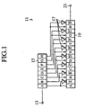
- the first conversion device 11 comprises an information input terminal 13 for sequentially inputting in serial the information blocks each of which is extracted sequentially from information sequence and acts as a conversion unit, a serial/parallel converter (referred to as an "S/P converter” hereinafter) 15 acting as a dividing means, a plurality of NOT circuits 17 each acting as a generating means to execute a logical NOT operation, a parallel/ serial converter (referred to as an "P/S converter” hereinafter) 19 acting as a combining means, and a code output terminal 21 for sequentially outputting in serial information allocated to every segment contained in the code blocks.
- S/P converter serial/parallel converter
- P/S converter parallel/ serial converter
- the S/P converter 15 divides 8-bit information blocks, for example, which are input serially via the information input terminal 13, into eight original subblocks A, B, C,...,H having a equal size and has a serial/parallel converting function for outputting original information, which are allocated to every segment contained in the original subblocks A, B, C,...,H, in parallel.
- Each of a plurality of NOT circuits 17 has a generating function for generating inverted subblocks containing inverted information, which are obtained by inverting all original information, while correlating the original subblocks with the inverted subblocks respectively.
- Such all original information are allocated to every segment contained in the divided original subblocks A, B, C,..., H, which are divided by the S/P converter 15.
- the P/S converter 19 has a combining function for combining a plurality of original subblocks A, B, C,...,H with a plurality of inverted subblocks, which are generated by a plurality of NOT circuits 17, together to thus convert 8-bit information blocks into 16-bit code blocks.
- the information allocated to every segment contained in the combined code blocks are output serially via the code output terminal 21.
- the P/S converter 19 is constructed to insert each inverted information corresponding to each original information into a next position adjacent to each original information such that the inverted information are correlated with the original information, which are allocated to every segment contained in a plurality of original subblocks A, B, C, ..., H, respectively.
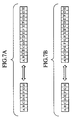
- the information in the code blocks are aligned such that, as shown in FIG.3, the original information and the inverted information corresponding to the original information are positioned alternatively.
- the S/P converter 15 divides 8-bit information blocks, which are input serially via the information input terminal 13 and each of which acts as a conversion unit, into eight equal original subblocks A, B, C,...,H and then outputs in parallel the original information, which are allocated to every segment contained in the original subblocks A, B, C, ..., H, respectively.
- each of a plurality of NOT circuits 17 generates the inverted subblocks containing inverted information, which are obtained by inverting all original information, while correlating the original subblocks A, B, C..., H with the inverted subblocks respectively. All original information are allocated to every segment contained in the original subblocks A, B, C,..., H, which are divided by the S/P converter 15.
- the P/S converter 19 combines a plurality of original subblocks A, B, C,...,H with a plurality of inverted subblocks, which are generated by a plurality of NOT circuits 17, together to thus convert the 8-bit information blocks into the 16-bit code blocks. Then, the information allocated to every segment contained in the combined code blocks are output serially via the code output terminal 21.
- the information blocks each serving as a conversion unit are converted into the code blocks in which the original information allocated to every segment contained in the information blocks and the inverted information are combined together such that the numbers of the original information in a block acting as a conversion unit and the inverted information are balanced.
- the information blocks can be converted into the code blocks via simple procedures while suppressing the direct current component.
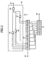
- the first restoration device 31 comprises a code input terminal 33 for inputting sequentially the code blocks which are extracted sequentially from the code sequence, which are converted by the first conversion device 11 and then sent out via a transmission line (not shown), for example, and each of which acts as a restoration unit; an S/P converter 35 for storing once the information, which are allocated to each segment contained in the 16-bit code blocks being input serially via the code input terminal 33, for example, and then outputting stored information in parallel by distributing such stored information to a P/S converter 37 and an error detection circuit 41 both described later; a P/S converter 37 serving as an original information sampling means; an information output terminal 39 for outputting serially the original information which are allocated to every segment contained in the original information blocks restored by the P/S converter 37; and an error detection circuit 41 serving as the original information sampling means, an inverted information sampling means, and a coincidence deciding means.
- the P/S converter 37 has an original information sampling function for sampling the original information, which are allocated to every segment contained in the original subblocks, from each of the original subblocks of the code blocks which are stored in the S/P converter 35 and each of which serves as a restoration unit. More particularly, the P/S converter 37 is constructed to restore the code blocks to the original information blocks by sampling selectively the original information from the information which are stored in the S/P converter 35 and contain the original information and the inverted information.
- the error detection circuit 41 is composed of a plurality of exclusive OR circuits 43 for executing an exclusive OR operation respectively, and an AND circuit 45 for executing an AND operation of outputs from a plurality of exclusive OR circuits 43.
- An output of the AND circuit 45 is output via a state output terminal 47.
- a plurality of exclusive OR circuits 43 have an original information sampling function and an inverted information sampling function.
- the information sampling function samples the original information, which are allocated to every segment contained in the original subblocks, from each of the original subblocks of the code blocks which are stored in the S/P converter 35 and serve as a restoration unit respectively.
- the inverted information sampling function samples the inverted information, which are allocated to every segment contained in the inverted subblocks, from each of the inverted subblocks of the code blocks each acting as a restoration unit.
- each of the plurality of exclusive OR circuits 43 is constructed to verify coincidence between the original information and the corresponding inverted information by sampling selectively a combination of mutually corresponding information from the information, which are stored in the S/P converter 35 and contain the original information and the inverted information, and then executing the exclusive OR operation of the information contained in the sampled combination.
- the AND circuit 45 has a coincidence deciding function for executing a coincidence decision to decide whether or not at least one combination in which both the original information and the inverted information coincide with each other is present in the combinations of the original information and the corresponding inverted information. More particularly, the AND circuit 45 is constructed to decide whether or not at least one combination in which both the original information and the inverted information coincide with each other exists, by applying the logical product operation to the result of the exclusive OR operation which is output from each of a plurality of exclusive OR circuits 43.
- the S/P converter 35 stores once the information, which are allocated to every segment contained in the 16-bit code blocks being input serially via the code input terminal 33, for example, and then outputs stored information in parallel by distributing such stored information to the P/S converter 37 and the error detection circuit 41.
- the P/S converter 37 restores the code blocks to the original information blocks by sampling the original information, which are allocated to every segment contained in the original subblocks, from each of the original subblocks of the code blocks which are stored in the S/P converter 35 and each of which serves as a restoration unit, and then outputs the restored information via the information output terminal 39.
- the first restoration device 31 a restoration device which is optimal to restore the code blocks obtained by the conversion into the original information blocks can be achieved.
- each of a plurality of exclusive OR circuits 43 verifies the coincidence between the original information and the corresponding inverted information by sampling selectively a combination of mutually corresponding information from the information which are stored in the S/P converter 35 and contain the original information and the inverted information, and then executing the exclusive OR operation of the information contained in the sampled combination. More particularly, the exclusive OR circuits 43 output "1" when the information contained in the combination are different like “0” and “1", and output "0" when the information contained in the combination coincide mutually like “1” and “1", or "0" and "0". As a result, error occurring locations, in which the original information and the corresponding inverted information coincide with each other, can be identified easily by monitoring respective outputs from a plurality of exclusive OR circuits 43.
- the AND circuit 45 executes the coincidence decision to decide whether or not at least one combination in which the original information coincide with the corresponding inverted information is present, by executing the AND operation of the results of the exclusive OR operation. Then, this result of the coincidence decision, i.e., the error detection result is output via the state output terminal 47. In other words, since the AND circuit 45 outputs "1" under the normal condition and outputs "0" under the abnormal condition, the effect of generation of the abnormal condition can be easily recognized by monitoring this output.
- the first restoration device 31 deems that the abnormal condition is caused, and then outputs such effect.
- the sender can inform the destination of the generation of the abnormal condition without fail by including forcibly at least one combination, in which the original information and the corresponding inverted information coincide with each other, into the code blocks on the sender side.
- the transmission error and the restoration error are contained in the abnormal condition.
- generation of the code error such as the transmission error, the restoration error, etc. is assumed when at least one combination in which the original information and the corresponding inverted information coincide with each other is present, the restoring device which makes it possible to detect the code error easily can be achieved.
- the error detecting process in addition to the above monitoring of the outputs of a plurality of exclusive OR circuits 43 and the output of the AND circuit 45, for example, the error detecting process can also be accomplished by counting the numbers of the original information and the inverted information respectively because the original information and the inverted information, which are contained in the code block acting as the restoration unit are balanced in number.
- the higher precision error detecting process can be realized if the already known cyclic redundancy check (CRC), the parity check, etc. are applied in combination.
- CRC cyclic redundancy check
- parity check etc.
- an error code correction circuit (not shown), for example, the error code correcting process is applied to the error occurring locations in which the original information and the corresponding inverted information coincide with each other.
- the error code correcting process for example, in view of the fact that the original information and the inverted information which are contained in the code block acting as the restoration unit are balanced in number, it is possible to identify that the error is caused in either the original information or the inverted information, by referring to both the code error locations detected by the error detecting process and the counted result of the numbers of the original information and the inverted information. Then, the error code correcting process for correcting the false information can be carried out based on this identification result.
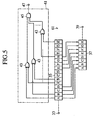
- the second conversion device 51 comprises the information input terminal 13, the S/P converter 15, a plurality of NOT circuits 17, the P/S converter 19, and the code output terminal 21.
- the S/P converter 15 divides 8-bit information blocks, for example, which are input serially via the information input terminal 13, into two original subblocks P 1 , P 2 having a equal size, and has a serial/parallel converting function for outputting the original information, which are allocated to every segment contained in the original subblocks P 1 , P 2 , in parallel.
- Each of a plurality of NOT circuits 17 has a generating function for generating inverted subblocks P 1 *, P 2 * containing inverted information, which are obtained by inverting all original information, while correlating the original subblocks P 1 , P 2 with the inverted subblocks P 1 *, P 2 * respectively.
- Such all original information are allocated to every segment contained in the original subblocks P 1 , P 2 , which are divided by the S/P converter 15.
- the P/S converter 19 has a combining function for combining a plurality of original subblocks P 1 , P 2 with a plurality of inverted subblocks P 1 *, P 2 *, which are generated by a plurality of NOT circuits 17, together to thus convert the 8-bit information blocks into the 16-bit code blocks.
- the information allocated to every segment contained in the combined code blocks are output serially via the code output terminal 21.
- the P/S converter 19 is constructed to insert each of a plurality of concerned inverted subblocks P 1 *, P 2 * into a next position adjacent to each of the original subblocics P 1 , P 2 such that the inverted subblocks P 1 *, P 2 * are correlated with a plurality of original subblocks P 1 , P 2 respectively.
- the information in the code blocks are aligned such that, as shown in FIG. 6, the original subblocks P 1 , P 2 and the inverted subblocks P 1 *, P 2 * corresponding to the original subblocics P 1 , P 2 are positioned alternatively.
- the S/P converter 15 divides the 8-bit information blocks, which are input serially via the information input terminal 13 and each of which acts as a conversion unit, into two equal original subblocks P 1 , P 2 and then outputs in parallel the original information, which are allocated to every segment contained in the original subblocks P 1 , P 2 , respectively.
- each of a plurality of NOT circuits 17 generates the inverted subblocks P 1 *, P 2 * containing inverted information, which are obtained by inverting all original information, while correlating the original subblocks P 1 , P 2 with the inverted subblocks P 1 *, P 2 * respectively. All original information are allocated to every segment contained in the original subblocks P 1 , P 2 which are divided by the S/P converter 15.
- the P/S converter 19 combines a plurality of original subblocks P 1 , P 2 with a plurality of inverted subblocks P 1 *, P 2 *, which are generated by a plurality of NOT circuits 17, together to thus convert the 8-bit information blocks into the 16-bit code blocks. Then, the information allocated to every segment contained in the combined code blocks are output serially via the code output terminal 21.
- the information blocks each serving as a conversion unit are converted into the code blocks in which the original information allocated to every segment contained in the information blocks and the inverted information are combined together, and thus the original information in a block acting as a conversion unit and the inverted information are balanced in number.
- the information blocks can be converted into the code blocks through simple procedures.
- the second restoration device 61 comprises the code input terminal 33, the S/P converter 35, the P/S converter 37, the information output terminal 39, and the error detection circuit 41.
- the P/S converter 37 is constructed to restore the code blocks to the original information blocks by sampling selectively the original information from the information which are stored in the S/P converter 35 and contain the original information and the inverted information.
- the error detection circuit 41 is constructed to include a plurality of exclusive OR circuits 43, and the AND circuit 45.
- the output of the AND circuit 45 is output via the state output terminal 47.
- the S/P converter 35 stores once the information, which are allocated to every segment contained in the 16-bit code blocks being input serially via the code input terminal 33, for example, and then outputs stored information in parallel to distribute such stored information to the P/S converter 37 and the error detection circuit 41.
- the P/S converter 37 restores the code blocks to the original information blocks by sampling the original information, which are allocated to every segment contained in the original subblocks P 1 , P 2 , from each of the original subblocks P 1 , P 2 of the code blocks which are stored in the S/P converter 35 and each of which serves as a restoration unit, and then outputs the restored information via the information output terminal 39.
- the second restoration device 61 like the first restoration device 31, a restoration device which is optimal to restore the code blocks obtained by the conversion into the original information blocks can be achieved.
- predetermined conversion or restoration can be achieved by using the same procedures as those in the conversion devices and the restoration devices, explained above in detail.
- the conversion device or the restoration device is applied to the situation that, for example, the code blocks which are converted from the information blocks by the conversion device are transmitted to the restoration device via the transmission line and then the received code blocks are restored to the original information blocks by the restoration device. Since the simple device configuration is adopted in the present invention, the high speed operation can be easily affected. As a result, the operation of the device can be extremely stabilized even if the operating frequency of the code blocks is increased twice the operating frequency of the information blocks, so that no problem is caused.
- the driving of respective devices by the low voltage is implemented in the prior art.
- the reception error due to variation in the direct current component is ready to occur.
- the direct current component is completely removed in the present invention, there is no necessity that the above harmful influence due to the variation in the direct current component must be considered.
- the electromagnetic interference (EMI) due to the high operating frequency can be reduced without the reception error by driving respective devices by the low voltage.
- the information alignment in the code blocks is explained such that, after the information are converted by the conversion device, the original information and the inverted information corresponding to the original information are positioned alternatively.
- the present invention is not limited to such embodiments. It is needless to say that the original information and the inverted information corresponding to the original information can be arranged freely to have any positional relation within the range of the code blocks acting as conversion objects.
Landscapes
- Engineering & Computer Science (AREA)
- Theoretical Computer Science (AREA)
- Compression, Expansion, Code Conversion, And Decoders (AREA)
- Dc Digital Transmission (AREA)
Applications Claiming Priority (2)
| Application Number | Priority Date | Filing Date | Title |
|---|---|---|---|
| JP29714098 | 1998-10-19 | ||
| JP29714098A JP3578645B2 (ja) | 1998-10-19 | 1998-10-19 | 変換方法、復調方法、変換装置、及び復調装置 |
Publications (2)
| Publication Number | Publication Date |
|---|---|
| EP1001539A2 true EP1001539A2 (fr) | 2000-05-17 |
| EP1001539A3 EP1001539A3 (fr) | 2001-04-25 |
Family
ID=17842735
Family Applications (1)
| Application Number | Title | Priority Date | Filing Date |
|---|---|---|---|
| EP99120053A Ceased EP1001539A3 (fr) | 1998-10-19 | 1999-10-19 | Méthode de conversion, méthode de restauration, dispositif de conversion, et dispositif de restauration |
Country Status (3)
| Country | Link |
|---|---|
| US (1) | US6373405B1 (fr) |
| EP (1) | EP1001539A3 (fr) |
| JP (1) | JP3578645B2 (fr) |
Families Citing this family (4)
| Publication number | Priority date | Publication date | Assignee | Title |
|---|---|---|---|---|
| DE19738362B4 (de) * | 1997-09-02 | 2006-11-02 | Siemens Ag | Schaltungsanordnung und Verfahren zur Minimierung von Bitfehlern |
| JP4578328B2 (ja) * | 2005-06-02 | 2010-11-10 | 東芝三菱電機産業システム株式会社 | シリアル信号伝送方法 |
| JP5644570B2 (ja) | 2011-02-16 | 2014-12-24 | ミツミ電機株式会社 | 通信方法、通信システム及びそのデバイス |
| JP2017076854A (ja) * | 2015-10-14 | 2017-04-20 | 富士通株式会社 | 電子装置、及びデータ検証方法 |
Family Cites Families (9)
| Publication number | Priority date | Publication date | Assignee | Title |
|---|---|---|---|---|
| JPS5013046B1 (fr) * | 1970-07-31 | 1975-05-16 | ||
| US3742199A (en) * | 1970-09-21 | 1973-06-26 | Larse Corp | Binary code communication system |
| JPH0714145B2 (ja) | 1983-04-26 | 1995-02-15 | ソニー株式会社 | 情報変換方法 |
| US4598326A (en) | 1983-10-18 | 1986-07-01 | Honeywell Inc. | Digital recording apparatus with disparity reducing encoder |
| JPH0683271B2 (ja) * | 1983-10-27 | 1994-10-19 | ソニー株式会社 | 情報変換方式 |
| DE69328642T2 (de) * | 1992-02-19 | 2001-01-11 | Mitsubishi Denki K.K., Tokio/Tokyo | Datenumsetzungsverfahren und Aufzeichnungs-/Wiedergabegerät zur Durchführung desselben |
| US5537112A (en) * | 1994-01-12 | 1996-07-16 | Seagate Technology, Inc. | Method and apparatus for implementing run length limited codes in partial response channels |
| US5781133A (en) * | 1996-08-05 | 1998-07-14 | Seagate Technology, Inc. | Method and apparatus for implementing run length limited codes |
| US6211801B1 (en) * | 1998-04-17 | 2001-04-03 | Netergy Networks | Data communication arrangement having variable length coding and method therefor |
-
1998
- 1998-10-19 JP JP29714098A patent/JP3578645B2/ja not_active Expired - Fee Related
-
1999
- 1999-10-18 US US09/419,634 patent/US6373405B1/en not_active Expired - Fee Related
- 1999-10-19 EP EP99120053A patent/EP1001539A3/fr not_active Ceased
Also Published As
| Publication number | Publication date |
|---|---|
| US6373405B1 (en) | 2002-04-16 |
| EP1001539A3 (fr) | 2001-04-25 |
| JP2000124960A (ja) | 2000-04-28 |
| JP3578645B2 (ja) | 2004-10-20 |
Similar Documents
| Publication | Publication Date | Title |
|---|---|---|
| EP0443754A2 (fr) | Méthode et appareil de détection d'un mot d'alignement de trame dans un courant de données | |
| US6601210B1 (en) | Data integrity verification in a switching network | |
| EP0692167A1 (fr) | Appareil et procede de transmission d'informations entre des composants doubles et redondants a l'aide de quatre chemins de signaux | |
| US5148453A (en) | Parallel sync detection | |
| US6373405B1 (en) | Conversion method, restoration method, conversion device, and restoration device | |
| US6369723B1 (en) | Replacement of special characters in a data stream | |
| EP0474241B1 (fr) | Détection de violation de code HDB3 | |
| US6886126B1 (en) | Apparatus and protocol for detected error propagation in serial-transport block-coded interfaces | |
| US5671228A (en) | System for detecting non-coincidence of codes | |
| KR970007264B1 (ko) | 멀티 채널 디코더 및 디코딩방법 | |
| JP3095407B2 (ja) | 多重分離装置 | |
| KR19990038709U (ko) | 패리트 비트를 이용한 에러 검출 장치 | |
| KR100299849B1 (ko) | 시디엠에이 이동통신 시스템의 기지국용 모뎀 출력 디지털조합기 | |
| JPH03159421A (ja) | データ伝送システムにおける最適誤り訂正符号化選択方式 | |
| JPH10222386A (ja) | パリティエラー検出方式 | |
| KR950004241B1 (ko) | 패리티 검사에 의한 데이타오류 검출장치 | |
| JP2555582B2 (ja) | Cmi符号誤り検出回路 | |
| EP0257414A2 (fr) | Détection et correction rapide d'erreur pour des signaux de commande | |
| JP2006270211A (ja) | シリアル信号伝送システム | |
| JP2759607B2 (ja) | 同期信号検出装置 | |
| JPS62115936A (ja) | エラ−レ−ト検出方式 | |
| JP3410993B2 (ja) | 誤り訂正装置 | |
| JPS5868343A (ja) | 巡回符号検定方式による伝送デ−タのエラ−検定方式 | |
| IL148262A (en) | Data integrity verification in a switching network | |
| JPH05300117A (ja) | フレーム変換エラー検出回路 |
Legal Events
| Date | Code | Title | Description |
|---|---|---|---|
| PUAI | Public reference made under article 153(3) epc to a published international application that has entered the european phase |
Free format text: ORIGINAL CODE: 0009012 |
|
| 17P | Request for examination filed |
Effective date: 19991019 |
|
| AK | Designated contracting states |
Kind code of ref document: A2 Designated state(s): DE FR GB |
|
| AX | Request for extension of the european patent |
Free format text: AL;LT;LV;MK;RO;SI |
|
| PUAL | Search report despatched |
Free format text: ORIGINAL CODE: 0009013 |
|
| RIC1 | Information provided on ipc code assigned before grant |
Free format text: 7H 03M 5/14 A, 7G 11B 5/09 B |
|
| AK | Designated contracting states |
Kind code of ref document: A3 Designated state(s): AT BE CH CY DE DK ES FI FR GB GR IE IT LI LU MC NL PT SE |
|
| AX | Request for extension of the european patent |
Free format text: AL;LT;LV;MK;RO;SI |
|
| AKX | Designation fees paid |
Free format text: DE FR GB |
|
| 17Q | First examination report despatched |
Effective date: 20020425 |
|
| STAA | Information on the status of an ep patent application or granted ep patent |
Free format text: STATUS: THE APPLICATION HAS BEEN REFUSED |
|
| 18R | Application refused |
Effective date: 20050411 |