EP1001577A1 - Archtitektur eines Sprache über Internet Protokoll Netz - Google Patents
Archtitektur eines Sprache über Internet Protokoll Netz Download PDFInfo
- Publication number
- EP1001577A1 EP1001577A1 EP99308872A EP99308872A EP1001577A1 EP 1001577 A1 EP1001577 A1 EP 1001577A1 EP 99308872 A EP99308872 A EP 99308872A EP 99308872 A EP99308872 A EP 99308872A EP 1001577 A1 EP1001577 A1 EP 1001577A1
- Authority
- EP
- European Patent Office
- Prior art keywords
- nodes
- tunnel
- signalling
- network
- tunnels
- Prior art date
- Legal status (The legal status is an assumption and is not a legal conclusion. Google has not performed a legal analysis and makes no representation as to the accuracy of the status listed.)
- Granted
Links
- 230000011664 signaling Effects 0.000 claims abstract description 24
- 239000012092 media component Substances 0.000 claims abstract description 8
- 238000000034 method Methods 0.000 claims description 15
- 230000000052 comparative effect Effects 0.000 description 3
- 239000004248 saffron Substances 0.000 description 3
- 230000005540 biological transmission Effects 0.000 description 2
- 239000004744 fabric Substances 0.000 description 2
- 230000008569 process Effects 0.000 description 2
- 238000013519 translation Methods 0.000 description 2
- 230000014616 translation Effects 0.000 description 2
- 235000008694 Humulus lupulus Nutrition 0.000 description 1
- 230000006978 adaptation Effects 0.000 description 1
- 238000004891 communication Methods 0.000 description 1
- 238000000354 decomposition reaction Methods 0.000 description 1
- 230000004069 differentiation Effects 0.000 description 1
- 238000012423 maintenance Methods 0.000 description 1
- 230000007246 mechanism Effects 0.000 description 1
- 238000012986 modification Methods 0.000 description 1
- 230000004048 modification Effects 0.000 description 1
- 238000012545 processing Methods 0.000 description 1
- 230000004044 response Effects 0.000 description 1
- 238000005204 segregation Methods 0.000 description 1
- 230000007727 signaling mechanism Effects 0.000 description 1
Images


Classifications
-
- H—ELECTRICITY
- H04—ELECTRIC COMMUNICATION TECHNIQUE
- H04Q—SELECTING
- H04Q3/00—Selecting arrangements
- H04Q3/0016—Arrangements providing connection between exchanges
- H04Q3/0029—Provisions for intelligent networking
- H04Q3/0045—Provisions for intelligent networking involving hybrid, i.e. a mixture of public and private, or multi-vendor systems
-
- H—ELECTRICITY
- H04—ELECTRIC COMMUNICATION TECHNIQUE
- H04Q—SELECTING
- H04Q3/00—Selecting arrangements
- H04Q3/0016—Arrangements providing connection between exchanges
- H04Q3/0025—Provisions for signalling
Definitions
- This invention relates to systems and methods for providing and managing Internet protocol (IP) connection oriented services.
- IP Internet protocol
- connectionless services These services normally operate on a best effort basis.
- voice services normally operate on a best effort basis.
- costs are significantly less than those associated with the conventional PSTN.
- adaptation of what is effectively a high priority connection oriented service to a 'best effort' connectionless or packet system has introduced a number of significant problems.
- an Internet voice service is to obtain universal acceptance, it must provide a quality of service similar to that currently provided by conventional voice networks.
- the current Internet Ipv4 protocol includes a TOS (type of service) octet, and Ipv6 a traffic class octet which allows a number of priority levels to be defined to support some degree of traffic engineering in an IP network.
- the IETF Differentiated Services Working Group has recently defined a method whereby traffic is classified at a priority level and is policed on entry to an IP network. Traffic behaviour on internal links (per hop behaviour) is specified. It is expected that using these methods then service level agreements can be offered to users provided that the number of internal hops is low and also provided that the percentage of high priority traffic is a small percentage of the total traffic.
- Connection orientation is of particular value in the provision of carrier network services to individual users or to user networks. In particular it simplifies the tasks of:-
- An object of the invention is to minimise or to overcome the above disadvantage.
- ITU Signalling System No 7 is of considerable value in Voice over IP networks as it allows access to Intelligent Network applications of the PSTN/ISDN and also provides service transparency whereby services such as Call Waiting can operate consistently for ISDN to ISDN, VoIP to ISDN and VoIP to VoIP calls.
- the invention provides an arrangement for providing voice and media service components over an IP network incorporating a plurality of nodes and in which connection oriented traffic is transported in tunnels via said nodes, the arrangement comprising means for providing signalling between said nodes, and means for multiplexing the voice and media components to form a point to point protocol (PPP) session, and means for switching said PPP session end to end across the network under the control of said signalling.
- PPP point to point protocol
- the invention provides a method of providing voice and media service components over an IP network incorporating a plurality of nodes, the method comprising providing signalling between said nodes, and multiplexing the voice and media components to form a point to point protocol (PPP) session which session is switched end to end across the network under the control of said signalling.
- PPP point to point protocol
- the signalling comprises SS7 signalling.
- the network tunnels comprise Layer 2 Tunnelling Protocol (L2TP) tunnels and Multi Protocol Label Switching (MPLS) tunnels.
- L2TP Layer 2 Tunnelling Protocol
- MPLS Multi Protocol Label Switching
- gatekeepers are provided at either end of each tunnel so as to control the number of calls admitted to that tunnel. This enables the provision of quality of service guarantees to the admitted traffic.
- This invention thus provides a network architecture for Voice over IP services in which e.g. SS7 signalling is used between Voice over IP nodes and the media components between the VoIP terminals are multiplexed to form a PPP Session which is switched end to end across the wide area network.
- SS7 signalling is used between Voice over IP nodes and the media components between the VoIP terminals are multiplexed to form a PPP Session which is switched end to end across the wide area network.
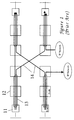
- FIG 1 which is introduced for explanatory and comparative purposes, this shows a prior art MPLS network.
- the network comprises a number of MPLS edge routers 11 and MPLS switching nodes 12.
- Such a network allows tunnels to be defined and used for explicit end to end routing of packets. Packet traffic contained within a tunnel passing through a switching node is effectively ignored by that node as far as routing is concerned.
- the tunnels can be defined at several layers, and tunnels of one layer can be carried within tunnels of other layers.
- engineering tunnels 13a, 13b etc. are defined for an engineering layer which is used to divide up capacity in the physical network, and user tunnels 14, which utilise capacity of the engineering tunnels, are defined in order to provide end user services.
- An engineering tunnel may of course accommodate a number of user tunnels, and a user tunnel will, in general, pass through more than one engineering tunnel.
- the user tunnel 14 is contained in the engineering tunnels 13a and 13b.
- a typical end user service would be a guaranteed bandwidth service between two VPN user nodes.
- an engineering tunnel is a permanent or semi-permanent entity that is set up across a number of network nodes, but which does not in general provide a complete end to end route across the network.
- a user tunnel is a temporary entity that is set up within an appropriate number of engineering tunnels to provide end to end connectivity for the duration of a network transaction, and which is torn down when that transaction has been completed.
- the purpose of a tunnel is to facilitate routing of packets.
- a packet within a tunnel can pass through a node without that node needing to have any knowledge of the destination of that packet, nor even of the next node at which the packet will arrive, as the packet can remain within the tunnel until emerging at its final destination.
- the only information required by the node is the identity of the tunnel via which the packet is transported. It will be understood that an IP network incorporating the tunnel concept may carry both tunnelled packet traffic and conventional packet traffic that is routed at each system node through which it passes.
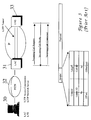
- the multi protocol label switching (MPLS) operation of the network of figure 1 is depicted in figure 2 which illustrates the typical packet format P1-P6 at each of the stages in the routing of an IP packet payload end to end across the network of figure 1.
- a typical MPLS packet comprises the original IP packet together with a stack of labels which are used by the MPLS nodes 12 through which the packet passes to control the onward routing of the packet.
- the current packet label is used to determine the onward routing of the packet, i.e. the tunnel to which the packet is allocated.
- the labels are typically each of 4 bytes length comprising a 20 bit label value, a 3 bit class of service field, used to maintain QoS differentiation, a 1 bit "bottom of stack” indicator and an 8 bit "time to live” field, which is used to detect packet forwarding loops.
- the packet formats P1-P6 are selected in order to achieve explicit forwarding of the packet over a user tunnel which is itself contained within first and second engineering tunnels in order to reach the destination edge router.
- MPLS is designed such that it is possible, at each node, to forward the packet based on the label at the top of the stack.
- the packet format P1 has labels L-d, L-u1, and L-ex.
- the label L-d is significant to the destination edge router 11b and is a label exchanged by the label distribution protocol over the user tunnel.
- L-u1 is the first label of a series used for the user tunnel and is exchanged over the first engineering tunnel 13a.
- L-ex is a label for the engineering tunnel 13a.
- the packet format P2 is used by the first node 12 to determine that this is the penultimate node for the first engineering tunnel 13a. This leads to a "pop" of the stack so that the labels L-d and L-u1 are forwarded to the next node. It will be understood that the term “popping" of a label stack refers to the removal of the label currently at the head of the stack, and that the term “pushing" of a label refers to the addition of a label to the stack.
- the label L-u1 of the packet format P3 is used to forward the packet and is translated to the label L-u2 for the next hop.
- the label L-u2 of the packet format P4 is used for forwarding. It is determined that this is the penultimate hop from the perspective of the user tunnel so label L-u2 is popped. It is also determined that the second engineering tunnel 13b is used, L-ey being a label for the engineering tunnel 13b. The packet is therefore forwarded with the labels L-d and L-ey.
- the label L-ey of the packet format P5 is popped so the packet arrives at the destination edge router 11b with the label L-d only.
- the original IP packet (format P6) is forwarded to the final destination on the Lan.
- L2TP layer 2 tunnelling Protocol
- L2TP is used for dial-up services where the point of network service is different from the point at which the original dialup call is made.
- An example is Internet service provider (ISP) roaming whereby the dialup is terminated at the nearest ISP but the network service is provided by the original or home ISP.
- ISP Internet service provider
- L2TP provides a connection signalling mechanism so that point to point protocol (PPP) sessions can be dynamically multiplexed within the tunnel.
- PPP payload packets have a short header prepended thereto so that the original PPP packets can be identified and forwarded as appropriate.
- FIG 3 further illustrates a new call from a user terminal 30 arriving at a L2TP access concentrator (LAC) 31 from a dial-up modem connection set up via a PSTN 32.
- LAC L2TP access concentrator
- the associated messaging is illustrated in figure 3a. It is determined that the call is destined for a remote L2TP network server (LNS) 33 coupled to IP network 35.
- LNS L2TP network server
- a user tunnel 34 is thus established across the IP network between the concentrator 31 and the remote server 33.
- An exchange of messages within the L2TP tunnel 34 leads to an allocation of a call ID within the tunnel 34 which can be used to identify packets in both directions related to this call.
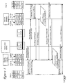
- the switch incorporates an inner core 40 comprising a set of ingress functions 45 coupled to respective ingress ports 47, and a set of egress functions 46 coupled to respective egress ports 48.
- Any ingress function can route a received packet to any egress function.
- the ingress and egress ports coupled to the respective ingress and egress functions handle packet traffic that is routed from node to node, i.e. not contained within a tunnel.
- Tunnel based traffic is received e.g. from tunnel T41 which either terminates at or passes through the node.
- the tunnel T41 may be an engineering tunnel accommodating a number of user tunnels.
- the lower half of figure 4 shows a decomposition of the ingress and egress functions of the switch.
- a Tunnel Status store provides an identification of whether the tunnel type is MPLS or L2TP and also the maintenance status of the tunnel. This is used by the L2TP/label header discriminator to access the header information and to execute any required Push/Pop operation.
- the header information is used to access the Call Id translation & segregation function in order to identify the required egress function and to modify the L2TP headers for onward transmission.
- the packet is then forwarded on a link to the required egress function. In the typical switch fabrics, e.g. ATM, the packet will have been segmented for transport purposes.
- the packet is reassembled in the egress function for egress control purposes, the header of the packet as modified by the ingress function providing all the control information required for egress.
- the tunnel status store discriminates between MPLS and L2TP operation.
- the header can be further processed by additional push/pop operations or by Tunnel id/Call id translations.
- the packet is then passed to the scheduler for transmission.
- the scheduler includes a weighted fair queuing function in order to maintain a fair discard operation in the event of overload.
- IP packets that are received at the switch from tunnel T41 are output into tunnel T42. If the IP packets are already in MPLS format then they are directly forwarded to the inner core 41 of the switch.
- an additional function is required to process the IP address and establish an MPLS label according to the forwarding equivalence class, i.e. the set of IP addresses which share a common MPLS label. The provision of such a function will be understood by those skilled in the art.
- a switch on a single card is typically made up from four VLSI components, each of which provides 622 MB/s of switching capacity. Each VLSI component comprises an ingress function 45 and an egress function 46.
- the ingress function 45 processes the initial MPLS label. For normal MPLS packets, a treatment indicator determines whether to PUSH/POP the label stack and/or translate the label. Where the initial MPLS label indicates that an L2TP tunnel is contained within the label, then a second pass is performed interpreting the second header as an L2TP header with its own treatment indicator.
- the initial ingress function 45 selects an egress port 48 for forwarding. The packet is segmented by the ingress port 44 and forwarded typically as 64 byte segments to the egress port. The egress port reassembles the packet and has an additional treatment indicator, which it uses to prepend the final headers and labels before forwarding the packet on to the next switching node.
- the switch architecture of figure 4 embodies a connection control architecture which provides a range of connection oriented services in Internet Protocol (IP) networks.
- IP Internet Protocol
- This architecture which applies recursively at multiple levels, can be used to establish engineering tunnels in the physical network and user tunnels within these engineering tunnels.
- the architecture can also be used to establish PPP Sessions within a succession of L2TP tunnels.
- the L2TP tunnels can be mapped onto MPLS tunnels, and the MPLS tunnels can hide details of the IP network topology from the L2TP layer network.
- FIGS 5 and 5a these figures illustrate an exemplary embodiment in which two system nodes generally indicated as 10, each incorporating a respective L2TP tunnel switch 11, are interconnected through an ATM network 12.
- Each tunnel switch 11 is associated with a respective session manager 13.
- An application server 14 associated with the TM network 12 operates on a proxy signalling basis and requests point to point protocol (PPP) sessions on behalf of its clients.
- PPP point to point protocol
- Each PPP session request identifies its respective endpoints using layer 2 tunnelling protocol (L2TP) addressing with the address space covering a full E164 number.
- L2TP layer 2 tunnelling protocol
- the system operates on a source routed basis as in the case of the ATM Forum PNNI signalling system.
- the system nodes 10 exchange topology state packets identifying the network topology and reporting on available bandwidth or congestion so that each node has a picture of the current status of the network.
- a session request (A, B , DTL(N1,N2)) is a request for a PPP session between users A and B with a designated transit list (DTL) for network nodes N1 and N2.
- DTL transit list
- the topology state packets that are exchanged between the nodes provide sufficient information on bandwidth availability to ensure that the nodes N1 and N2 have a high probability to provide a successful routing.
- each L2TP Tunnel exchanges the standard sequence of messages defined for L2TP; i.e. Call Request, Call Reply and Call Connected. These messages may relate to outgoing calls or incoming calls.
- the session managers link the partial PPP sessions on each tunnel in order to provide an end to end PPP session via the tunnel.
- each gatekeeper 22 incorporates a call server function which is able to operate SS7 signalling with other gatekeepers or with PSTN/ISDN switches (not shown) in the external network.
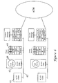
- the message sequence chart of figure 7 illustrates the end to end operation for a successful call set up in the network of figure 6.
- H.323 clients with E164 numbers A and B have respective proxy servers with E164 numbers P A and P B where A and P A are algorithmically related.
- user terminal A sends a set-up message (set-up(A,B)) for a call to user terminal B.
- DPC destination point code
- the circuit identification code designates a PPP session that is to be created on an L2TP Tunnel between the two tunnel switches.
- the terminating gatekeeper On receipt of the alerting message from the called user terminal B in response to the set-up request, the terminating gatekeeper requests a PPP session. This proceeds as described with reference to figure 1a above.
- the PPP session identifier of the proxy server P A (Tunnel ID, Call ID) is passed back to the terminating gatekeeper. This information is also passed to the originating gatekeeper as user to user information in the SS7 answer message ANM. This information allows the originating gatekeeper to complete the end to end connection.
- the L2TP signalling sequences exchange physical channel Ids, typically IP addresses, to enable packets to be exchanged between the proxy servers.
- H.245 capability messages are exchanged followed by requests to establish logical channels for communication.
- the H.245 messages are exchanged via the gatekeepers so that bandwidth accounting on the tunnels between the tunnel switches is possible.
- the media channels are routed end to end via the proxies using the IP addresses exchanged during set-up of the PPP sessions.
- the L2TP tunnel between the two tunnel switches behaves as an SS7 trunk group.
- the gatekeepers at either end of the tunnel are able to control the number of calls admitted allowing the network to be dimensioned for a grade of service as in normal telephony where all calls accepted have a guaranteed quality of service.
- the gatekeepers are also able to account for the total media components set up on the tunnel, this allows the available bandwidth to be dynamically shared amongst users and controlled by policies which can be based on congestion, user priorities and etc.
Landscapes
- Engineering & Computer Science (AREA)
- Computer Networks & Wireless Communication (AREA)
- Data Exchanges In Wide-Area Networks (AREA)
- Telephonic Communication Services (AREA)
Applications Claiming Priority (2)
| Application Number | Priority Date | Filing Date | Title |
|---|---|---|---|
| US190082 | 1998-11-12 | ||
| US09/190,082 US6507577B1 (en) | 1998-11-12 | 1998-11-12 | Voice over internet protocol network architecture |
Publications (2)
| Publication Number | Publication Date |
|---|---|
| EP1001577A1 true EP1001577A1 (de) | 2000-05-17 |
| EP1001577B1 EP1001577B1 (de) | 2006-03-22 |
Family
ID=22699952
Family Applications (1)
| Application Number | Title | Priority Date | Filing Date |
|---|---|---|---|
| EP99308872A Expired - Lifetime EP1001577B1 (de) | 1998-11-12 | 1999-11-08 | Architektur eines Sprache über Internet Protokoll Netz |
Country Status (4)
| Country | Link |
|---|---|
| US (1) | US6507577B1 (de) |
| EP (1) | EP1001577B1 (de) |
| CA (1) | CA2289394C (de) |
| DE (1) | DE69930482T2 (de) |
Cited By (6)
| Publication number | Priority date | Publication date | Assignee | Title |
|---|---|---|---|---|
| EP1246407A1 (de) * | 2001-03-22 | 2002-10-02 | Alcatel | Netzwerkeinheit und Verfahren zur Etikettenvermittlung |
| AU753098B2 (en) * | 1999-05-10 | 2002-10-10 | Distribution Systems Research Institute, The | Integrated IP network |
| WO2002069596A3 (en) * | 2001-02-21 | 2002-11-21 | Nokia Intelligent Edge Routers | Service tunnel over a connectionless network |
| US6934280B1 (en) | 2000-05-04 | 2005-08-23 | Nokia, Inc. | Multiple services emulation over a single network service |
| WO2007061465A1 (en) * | 2005-11-16 | 2007-05-31 | Sbc Knowledge Ventures, L.P. | Digital subscriber link interconnection to a virtual private network |
| KR100748312B1 (ko) | 2004-09-24 | 2007-08-09 | 주식회사 케이티 | 범용 단말기에서 서비스 품질 보장을 위한 어플리케이션트래픽 전송 방법 |
Families Citing this family (87)
| Publication number | Priority date | Publication date | Assignee | Title |
|---|---|---|---|---|
| US20020118671A1 (en) * | 1995-11-15 | 2002-08-29 | Data Race, Inc. | Extending office telephony and network data services to a remote client through the internet |
| US7283561B1 (en) * | 1997-12-12 | 2007-10-16 | Level 3 Communications, Llc | Secure network architecture with quality of service |
| EP1074150B1 (de) * | 1998-04-22 | 2002-12-04 | Siemens Aktiengesellschaft | Signalisierungseinrichtung in einem signalisierungssystem |
| US6973057B1 (en) * | 1999-01-29 | 2005-12-06 | Telefonaktiebolaget L M Ericsson (Publ) | Public mobile data communications network |
| GB9905509D0 (en) * | 1999-03-10 | 1999-05-05 | Northern Telecom Ltd | Label switched media gateway and network |
| US6275470B1 (en) * | 1999-06-18 | 2001-08-14 | Digital Island, Inc. | On-demand overlay routing for computer-based communication networks |
| US6701439B1 (en) * | 1999-06-30 | 2004-03-02 | Lucent Technologies Inc. | Call rejection interface for internet protocols |
| US6882643B1 (en) * | 1999-07-16 | 2005-04-19 | Nortel Networks Limited | Supporting multiple services in label switched networks |
| US7359960B1 (en) * | 1999-07-20 | 2008-04-15 | Net2Phone, Inc. | Telecommunications control system using data interchange |
| US7136387B2 (en) * | 1999-08-09 | 2006-11-14 | Mci, Llc | Method of and system for providing quality of service in IP telephony |
| KR100326332B1 (ko) * | 1999-09-06 | 2002-03-08 | 윤종용 | 패킷 교환 형태 네트워크의 단말기와 원격 접근 서버를 통해접속하는 단말기간의 통화 방법 |
| US6674760B1 (en) * | 1999-09-28 | 2004-01-06 | Extreme Networks, Inc. | Method and system for implementing end-to-end QoS in packet-switched networks |
| US6687243B1 (en) * | 1999-09-29 | 2004-02-03 | Cisco Technology, Inc. | Method and apparatus for integrated wireless communications in private and public network environments |
| US7046786B2 (en) * | 1999-10-19 | 2006-05-16 | Cisco Technology, Inc. | Method and apparatus for transporting data using label switching |
| JP4031894B2 (ja) * | 1999-10-29 | 2008-01-09 | 富士通株式会社 | Mpls通信方式における通信データ確認試験方法及びその方法を利用するルータ,交換機,通信システム |
| US7016973B1 (en) * | 1999-11-19 | 2006-03-21 | At&T Corp. | Apparatus and methods for providing translucent proxies in a communications network |
| US6707813B1 (en) * | 2000-02-21 | 2004-03-16 | Telefonaktiebolaget L M Ericsson (Publ) | Method of call control to minimize delays in launching multimedia or voice calls in a packet-switched radio telecommunications network |
| US6614809B1 (en) * | 2000-02-29 | 2003-09-02 | 3Com Corporation | Method and apparatus for tunneling across multiple network of different types |
| JP3479908B2 (ja) * | 2000-03-24 | 2003-12-15 | 日本電気株式会社 | VoIP用通信品質保証パス設定方法とネットワーク管理システム |
| EP1269736B1 (de) * | 2000-04-06 | 2008-12-17 | Nokia Siemens Networks Gmbh & Co. Kg | Bereitstellung von centrex-diensten in einem paketvermittelnden kommunikationsnetz |
| WO2001078416A1 (de) * | 2000-04-06 | 2001-10-18 | Siemens Aktiengesellschaft | Verarbeitung von signalisierungsdaten und verbindungssteuerung von teilnehmern eines paketvermittelnden kommunikationsnetzes |
| JP3855595B2 (ja) * | 2000-04-25 | 2006-12-13 | 株式会社日立製作所 | 通信システム、通信方法及び通信装置 |
| US6601186B1 (en) * | 2000-05-20 | 2003-07-29 | Equipe Communications Corporation | Independent restoration of control plane and data plane functions |
| US6765915B1 (en) * | 2000-05-25 | 2004-07-20 | Conexant Systems, Inc. | Packet communication scheduling with hierarchical tunnels |
| AU2001267320A1 (en) * | 2000-06-07 | 2001-12-17 | Siemens Aktiengesellschaft | Method for transmitting voice information via an internet protocol |
| US7325058B1 (en) | 2000-11-13 | 2008-01-29 | Cisco Technology, Inc. | Method and system for controlling subscriber access in a network capable of establishing connections with a plurality of domain sites |
| US6874030B1 (en) | 2000-11-13 | 2005-03-29 | Cisco Technology, Inc. | PPP domain name and L2TP tunnel selection configuration override |
| US6650909B1 (en) * | 2000-11-22 | 2003-11-18 | Winphoria Networks, Inc. | System and method of preserving point codes in a mobile network having a proxy switch |
| US6625449B1 (en) * | 2000-11-22 | 2003-09-23 | Winphoria Netwroks, Inc. | System and method of siphoning messages from a mobile network to an alternative network |
| US20030003960A1 (en) * | 2000-12-01 | 2003-01-02 | Takahiro Shoji | Base station apparatus and channel access control method |
| US7325030B2 (en) | 2001-01-25 | 2008-01-29 | Yahoo, Inc. | High performance client-server communication system |
| US20020110087A1 (en) * | 2001-02-14 | 2002-08-15 | David Zelig | Efficient setup of label-switched connections |
| US7180855B1 (en) * | 2001-04-19 | 2007-02-20 | At&T Corp. | Service interface for QoS-driven HPNA networks |
| US7139276B1 (en) | 2001-02-27 | 2006-11-21 | Cisco Technology, Inc. | Load sharing between L2TP tunnels |
| US6847641B2 (en) * | 2001-03-08 | 2005-01-25 | Tellabs San Jose, Inc. | Apparatus and methods for establishing virtual private networks in a broadband network |
| US7023879B1 (en) * | 2001-03-09 | 2006-04-04 | Cisco Technology, Inc. | Dynamic multi-hop ingress to egress L2TP tunnel mapping |
| WO2002098075A1 (en) * | 2001-05-25 | 2002-12-05 | Mitsubishi Denki Kabushiki Kaisha | Internet communication system, internet communication method, session control server, communication adapter, communication relay server and program |
| US6816890B2 (en) * | 2001-05-28 | 2004-11-09 | Hitachi, Ltd. | Gateway apparatus with LAC function |
| US7117267B2 (en) * | 2001-06-28 | 2006-10-03 | Sun Microsystems, Inc. | System and method for providing tunnel connections between entities in a messaging system |
| US7206932B1 (en) | 2003-02-14 | 2007-04-17 | Crystalvoice Communications | Firewall-tolerant voice-over-internet-protocol (VoIP) emulating SSL or HTTP sessions embedding voice data in cookies |
| US7369537B1 (en) | 2001-07-18 | 2008-05-06 | Global Ip Solutions, Inc. | Adaptive Voice-over-Internet-Protocol (VoIP) testing and selecting transport including 3-way proxy, client-to-client, UDP, TCP, SSL, and recipient-connect methods |
| US7107344B2 (en) * | 2001-08-16 | 2006-09-12 | International Business Machines Corporation | Connection allocation technology |
| US7103671B2 (en) * | 2002-03-14 | 2006-09-05 | Yahoo! Inc. | Proxy client-server communication system |
| US7483399B2 (en) * | 2002-06-05 | 2009-01-27 | David Zelig | Signaling MPLS over RPR rings |
| DE10241197A1 (de) * | 2002-09-05 | 2004-03-25 | Siemens Ag | Verfahren zum Weiterleiten von Signalisierungsnachrichten und zugehörige Komponenten |
| DE10245562A1 (de) * | 2002-09-30 | 2004-04-15 | Siemens Ag | Datenkommunikationssystem, Rechner, sowie Datenkommunikatonsverfahren zum parallelen Betrieb von Standard-basierten und proprietären Ressourcen |
| US7792991B2 (en) * | 2002-12-17 | 2010-09-07 | Cisco Technology, Inc. | Method and apparatus for advertising a link cost in a data communications network |
| US7707307B2 (en) * | 2003-01-09 | 2010-04-27 | Cisco Technology, Inc. | Method and apparatus for constructing a backup route in a data communications network |
| US7869350B1 (en) | 2003-01-15 | 2011-01-11 | Cisco Technology, Inc. | Method and apparatus for determining a data communication network repair strategy |
| US7515605B2 (en) * | 2003-03-24 | 2009-04-07 | Corrigent Systems Ltd | Efficient transport of TDM services over packet networks |
| US7330440B1 (en) * | 2003-05-20 | 2008-02-12 | Cisco Technology, Inc. | Method and apparatus for constructing a transition route in a data communications network |
| US7864708B1 (en) | 2003-07-15 | 2011-01-04 | Cisco Technology, Inc. | Method and apparatus for forwarding a tunneled packet in a data communications network |
| US7466661B1 (en) | 2003-09-22 | 2008-12-16 | Cisco Technology, Inc. | Method and apparatus for establishing adjacency for a restarting router during convergence |
| US7580360B2 (en) * | 2003-10-14 | 2009-08-25 | Cisco Technology, Inc. | Method and apparatus for generating routing information in a data communications network |
| US7554921B2 (en) * | 2003-10-14 | 2009-06-30 | Cisco Technology, Inc. | Method and apparatus for generating routing information in a data communication network |
| US7710882B1 (en) | 2004-03-03 | 2010-05-04 | Cisco Technology, Inc. | Method and apparatus for computing routing information for a data communications network |
| US7551599B2 (en) * | 2004-03-29 | 2009-06-23 | Corrigent Systems Ltd. | Layer-3 network routing with RPR layer-2 visibility |
| CA2567303C (en) * | 2004-05-20 | 2015-03-24 | Freebit Co., Ltd. | Server for routing connection to client device |
| US7848240B2 (en) * | 2004-06-01 | 2010-12-07 | Cisco Technology, Inc. | Method and apparatus for forwarding data in a data communications network |
| US7577106B1 (en) | 2004-07-12 | 2009-08-18 | Cisco Technology, Inc. | Method and apparatus for managing a transition for a class of data between first and second topologies in a data communications network |
| US8374121B2 (en) * | 2004-08-13 | 2013-02-12 | Research In Motion Limited | Methods and apparatus for efficiently establishing and maintaining a data connection between a mobile station and a wireless network |
| US7330431B2 (en) * | 2004-09-03 | 2008-02-12 | Corrigent Systems Ltd. | Multipoint to multipoint communication over ring topologies |
| CN100450077C (zh) * | 2004-09-15 | 2009-01-07 | 华为技术有限公司 | 一种在网络中路由转发的方法 |
| US7630298B2 (en) * | 2004-10-27 | 2009-12-08 | Cisco Technology, Inc. | Method and apparatus for forwarding data in a data communications network |
| US7496644B2 (en) * | 2004-11-05 | 2009-02-24 | Cisco Technology, Inc. | Method and apparatus for managing a network component change |
| US7974223B2 (en) * | 2004-11-19 | 2011-07-05 | Corrigent Systems Ltd. | Virtual private LAN service over ring networks |
| US7933197B2 (en) * | 2005-02-22 | 2011-04-26 | Cisco Technology, Inc. | Method and apparatus for constructing a repair path around a non-available component in a data communications network |
| WO2006116396A2 (en) * | 2005-04-26 | 2006-11-02 | Anders Joseph C | Voice over internet protocol system and method for processing of telephonic voice over a data network |
| US7848224B2 (en) * | 2005-07-05 | 2010-12-07 | Cisco Technology, Inc. | Method and apparatus for constructing a repair path for multicast data |
| US7515536B2 (en) * | 2005-07-11 | 2009-04-07 | Corrigent Systems Ltd. | Transparent transport of fibre channel traffic over packet-switched networks |
| US7835312B2 (en) * | 2005-07-20 | 2010-11-16 | Cisco Technology, Inc. | Method and apparatus for updating label-switched paths |
| US7693043B2 (en) * | 2005-07-22 | 2010-04-06 | Cisco Technology, Inc. | Method and apparatus for advertising repair capability |
| US7463580B2 (en) * | 2005-12-15 | 2008-12-09 | Corrigent Systems, Ltd. | Resource sharing among network tunnels |
| US7596088B2 (en) * | 2006-01-24 | 2009-09-29 | Corrigent Systems Ltd. | Route selection with bandwidth sharing optimization over rings |
| US20070242676A1 (en) * | 2006-04-13 | 2007-10-18 | Corrigent Systems Ltd. | Interface between a synchronous network and high-speed ethernet |
| US7701845B2 (en) | 2006-09-25 | 2010-04-20 | Cisco Technology, Inc. | Forwarding data in a data communications network |
| US20080309665A1 (en) * | 2007-06-13 | 2008-12-18 | 3D Systems, Inc., A California Corporation | Distributed rapid prototyping |
| US7940776B2 (en) * | 2007-06-13 | 2011-05-10 | Cisco Technology, Inc. | Fast re-routing in distance vector routing protocol networks |
| US8542578B1 (en) | 2010-08-04 | 2013-09-24 | Cisco Technology, Inc. | System and method for providing a link-state path to a node in a network environment |
| US11451464B2 (en) | 2019-05-13 | 2022-09-20 | 128 Technology, Inc. | Central authority for service and topology exchange |
| US11005749B2 (en) | 2019-05-13 | 2021-05-11 | 128 Technology, Inc. | Multicast source and receiver access control |
| US10999182B2 (en) | 2019-05-13 | 2021-05-04 | 128 Technology, Inc. | Routing using segment-based metrics |
| US12137045B2 (en) | 2019-05-13 | 2024-11-05 | Juniper Networks, Inc. | Metric-based multi-hop path selection |
| US11070465B2 (en) | 2019-05-13 | 2021-07-20 | 128 Technology, Inc. | Distribution of multicast information in a routing system |
| US11153202B2 (en) * | 2019-05-13 | 2021-10-19 | 128 Technology, Inc. | Service and topology exchange protocol |
| US11329912B2 (en) | 2019-05-13 | 2022-05-10 | 128 Technology, Inc. | Source-based routing |
| WO2021263047A1 (en) | 2020-06-24 | 2021-12-30 | Juniper Networks, Inc. | Layer-2 network extension over layer-3 network using encapsulation |
Citations (4)
| Publication number | Priority date | Publication date | Assignee | Title |
|---|---|---|---|---|
| EP0776107A2 (de) * | 1995-11-06 | 1997-05-28 | Xerox Corporation | Multimediakoordinationssystem |
| WO1998039934A2 (en) * | 1997-03-04 | 1998-09-11 | Northern Telecom Limited | Call redirection methods in a packet based communications network |
| WO1998054913A1 (en) * | 1997-05-30 | 1998-12-03 | Telefonaktiebolaget Lm Ericsson | A method and arrangement in communication networks for managing user related features through a user interface |
| EP0912027A2 (de) * | 1997-10-14 | 1999-04-28 | Lucent Technologies Inc. | System für das Übergreifen von Funktionsselektierung in einem Netzwerk |
Family Cites Families (5)
| Publication number | Priority date | Publication date | Assignee | Title |
|---|---|---|---|---|
| US5918019A (en) * | 1996-07-29 | 1999-06-29 | Cisco Technology, Inc. | Virtual dial-up protocol for network communication |
| CA2206616A1 (en) * | 1997-05-30 | 1998-11-30 | Robert Hugh Holt | Centralized call control in a data access transport service |
| US6084956A (en) * | 1997-09-19 | 2000-07-04 | Nortel Networks Corporation | SS7 mediation for data network call setup and services interworking |
| US6094437A (en) * | 1998-10-09 | 2000-07-25 | Asc - Advanced Switching Communications | Layer two tunneling protocol (L2TP) merging and management |
| US6349336B1 (en) * | 1999-04-26 | 2002-02-19 | Hewlett-Packard Company | Agent/proxy connection control across a firewall |
-
1998
- 1998-11-12 US US09/190,082 patent/US6507577B1/en not_active Expired - Lifetime
-
1999
- 1999-11-08 DE DE69930482T patent/DE69930482T2/de not_active Expired - Fee Related
- 1999-11-08 EP EP99308872A patent/EP1001577B1/de not_active Expired - Lifetime
- 1999-11-12 CA CA002289394A patent/CA2289394C/en not_active Expired - Fee Related
Patent Citations (4)
| Publication number | Priority date | Publication date | Assignee | Title |
|---|---|---|---|---|
| EP0776107A2 (de) * | 1995-11-06 | 1997-05-28 | Xerox Corporation | Multimediakoordinationssystem |
| WO1998039934A2 (en) * | 1997-03-04 | 1998-09-11 | Northern Telecom Limited | Call redirection methods in a packet based communications network |
| WO1998054913A1 (en) * | 1997-05-30 | 1998-12-03 | Telefonaktiebolaget Lm Ericsson | A method and arrangement in communication networks for managing user related features through a user interface |
| EP0912027A2 (de) * | 1997-10-14 | 1999-04-28 | Lucent Technologies Inc. | System für das Übergreifen von Funktionsselektierung in einem Netzwerk |
Cited By (8)
| Publication number | Priority date | Publication date | Assignee | Title |
|---|---|---|---|---|
| AU753098B2 (en) * | 1999-05-10 | 2002-10-10 | Distribution Systems Research Institute, The | Integrated IP network |
| US6934280B1 (en) | 2000-05-04 | 2005-08-23 | Nokia, Inc. | Multiple services emulation over a single network service |
| WO2002069596A3 (en) * | 2001-02-21 | 2002-11-21 | Nokia Intelligent Edge Routers | Service tunnel over a connectionless network |
| US7225259B2 (en) | 2001-02-21 | 2007-05-29 | Nokia Inc. | Service tunnel over a connectionless network |
| EP1246407A1 (de) * | 2001-03-22 | 2002-10-02 | Alcatel | Netzwerkeinheit und Verfahren zur Etikettenvermittlung |
| US7385979B2 (en) | 2001-03-22 | 2008-06-10 | Alcatel | Network-unit, and telecommunication network, and method |
| KR100748312B1 (ko) | 2004-09-24 | 2007-08-09 | 주식회사 케이티 | 범용 단말기에서 서비스 품질 보장을 위한 어플리케이션트래픽 전송 방법 |
| WO2007061465A1 (en) * | 2005-11-16 | 2007-05-31 | Sbc Knowledge Ventures, L.P. | Digital subscriber link interconnection to a virtual private network |
Also Published As
| Publication number | Publication date |
|---|---|
| CA2289394A1 (en) | 2000-05-12 |
| DE69930482D1 (de) | 2006-05-11 |
| US6507577B1 (en) | 2003-01-14 |
| DE69930482T2 (de) | 2006-12-28 |
| CA2289394C (en) | 2009-01-13 |
| EP1001577B1 (de) | 2006-03-22 |
Similar Documents
| Publication | Publication Date | Title |
|---|---|---|
| EP1001577B1 (de) | Architektur eines Sprache über Internet Protokoll Netz | |
| US6522627B1 (en) | Managing internet protocol connection oriented services | |
| US7154889B1 (en) | Peer-model support for virtual private networks having potentially overlapping addresses | |
| EP1069742B1 (de) | Verfahren und Architektur zur Unterstüzung von mehreren Diensten in einem Etikettvermittlungsnetzwerk | |
| US6886043B1 (en) | Communications network | |
| US6765921B1 (en) | Communications network | |
| US7369556B1 (en) | Router for virtual private network employing tag switching | |
| US7983281B2 (en) | VPN composing method, interwork router, packet communication method, data communication apparatus, and packet relaying apparatus | |
| EP1213881B1 (de) | System und Verfahren zum Herstellen eines Kommunikationsweges auf einer ATM Plattform | |
| US6021263A (en) | Management of ATM virtual circuits with resources reservation protocol | |
| US6009097A (en) | System for routing packet switched traffic | |
| US5134610A (en) | Network transit prevention | |
| WO2000056113A1 (en) | Internet protocol switch and method | |
| US20050238001A1 (en) | Virtual ethernet mac switching | |
| US7023860B1 (en) | Communications network | |
| Busschbach | Toward QoS‐capable virtual private networks | |
| JP4181303B2 (ja) | コネクション型通信ネットワークにおいて使用可能なサービス品質特徴のコネクションレス型通信ネットワークへのマッピング方法およびその逆の方法 | |
| KR100204046B1 (ko) | 공중망 비동기 전달모드 교환시스템에서 광대역 전달 능력 정보요소 필드의 파라미터 설정 방법 | |
| CN1732652A (zh) | 虚拟以太网mac交换 | |
| Cocca et al. | Interaction of RSVP with ATM for the support of shortcut QoS Virtual Channels | |
| De Praetere et al. | Data networks integration | |
| KR20020081197A (ko) | Mpls 시스템에 사용되는 프로토콜의 구조 | |
| Nagami et al. | RFC2129: Toshiba's Flow Attribute Notification Protocol (FANP) Specification | |
| Veeraraghavan et al. | Exploiting the advantages of connectionless and connection-oriented networks | |
| Matsuzawa et al. | Network Working Group K. Nagami Request for Comments: 2129 Y. Katsube Category: Informational Y. Shobatake A. Mogi |
Legal Events
| Date | Code | Title | Description |
|---|---|---|---|
| PUAI | Public reference made under article 153(3) epc to a published international application that has entered the european phase |
Free format text: ORIGINAL CODE: 0009012 |
|
| AK | Designated contracting states |
Kind code of ref document: A1 Designated state(s): DE FR GB |
|
| AX | Request for extension of the european patent |
Free format text: AL;LT;LV;MK;RO;SI |
|
| RAP1 | Party data changed (applicant data changed or rights of an application transferred) |
Owner name: NORTEL NETWORKS LIMITED |
|
| 17P | Request for examination filed |
Effective date: 20001117 |
|
| AKX | Designation fees paid |
Free format text: DE FR GB |
|
| RAP1 | Party data changed (applicant data changed or rights of an application transferred) |
Owner name: NORTEL NETWORKS LIMITED |
|
| 17Q | First examination report despatched |
Effective date: 20040421 |
|
| GRAP | Despatch of communication of intention to grant a patent |
Free format text: ORIGINAL CODE: EPIDOSNIGR1 |
|
| GRAS | Grant fee paid |
Free format text: ORIGINAL CODE: EPIDOSNIGR3 |
|
| GRAA | (expected) grant |
Free format text: ORIGINAL CODE: 0009210 |
|
| AK | Designated contracting states |
Kind code of ref document: B1 Designated state(s): DE FR GB |
|
| REG | Reference to a national code |
Ref country code: GB Ref legal event code: FG4D |
|
| REF | Corresponds to: |
Ref document number: 69930482 Country of ref document: DE Date of ref document: 20060511 Kind code of ref document: P |
|
| PGFP | Annual fee paid to national office [announced via postgrant information from national office to epo] |
Ref country code: GB Payment date: 20060901 Year of fee payment: 8 |
|
| ET | Fr: translation filed | ||
| PLBE | No opposition filed within time limit |
Free format text: ORIGINAL CODE: 0009261 |
|
| STAA | Information on the status of an ep patent application or granted ep patent |
Free format text: STATUS: NO OPPOSITION FILED WITHIN TIME LIMIT |
|
| 26N | No opposition filed |
Effective date: 20061227 |
|
| PG25 | Lapsed in a contracting state [announced via postgrant information from national office to epo] |
Ref country code: DE Free format text: LAPSE BECAUSE OF NON-PAYMENT OF DUE FEES Effective date: 20070601 |
|
| REG | Reference to a national code |
Ref country code: FR Ref legal event code: ST Effective date: 20070731 |
|
| PG25 | Lapsed in a contracting state [announced via postgrant information from national office to epo] |
Ref country code: FR Free format text: LAPSE BECAUSE OF NON-PAYMENT OF DUE FEES Effective date: 20061130 |
|
| GBPC | Gb: european patent ceased through non-payment of renewal fee |
Effective date: 20071108 |
|
| PG25 | Lapsed in a contracting state [announced via postgrant information from national office to epo] |
Ref country code: GB Free format text: LAPSE BECAUSE OF NON-PAYMENT OF DUE FEES Effective date: 20071108 |