EP1001616A2 - Taktgenerator sowie Verfahren und Vorrichtung zur Bildanzeige - Google Patents
Taktgenerator sowie Verfahren und Vorrichtung zur Bildanzeige Download PDFInfo
- Publication number
- EP1001616A2 EP1001616A2 EP99308921A EP99308921A EP1001616A2 EP 1001616 A2 EP1001616 A2 EP 1001616A2 EP 99308921 A EP99308921 A EP 99308921A EP 99308921 A EP99308921 A EP 99308921A EP 1001616 A2 EP1001616 A2 EP 1001616A2
- Authority
- EP
- European Patent Office
- Prior art keywords
- signal
- division ratio
- frequency division
- frequency
- format
- Prior art date
- Legal status (The legal status is an assumption and is not a legal conclusion. Google has not performed a legal analysis and makes no representation as to the accuracy of the status listed.)
- Withdrawn
Links
Images



Classifications
-
- H—ELECTRICITY
- H04—ELECTRIC COMMUNICATION TECHNIQUE
- H04N—PICTORIAL COMMUNICATION, e.g. TELEVISION
- H04N5/00—Details of television systems
- H04N5/44—Receiver circuitry for the reception of television signals according to analogue transmission standards
- H04N5/455—Demodulation-circuits
-
- H—ELECTRICITY
- H04—ELECTRIC COMMUNICATION TECHNIQUE
- H04N—PICTORIAL COMMUNICATION, e.g. TELEVISION
- H04N5/00—Details of television systems
- H04N5/44—Receiver circuitry for the reception of television signals according to analogue transmission standards
- H04N5/46—Receiver circuitry for the reception of television signals according to analogue transmission standards for receiving on more than one standard at will
-
- H—ELECTRICITY
- H04—ELECTRIC COMMUNICATION TECHNIQUE
- H04N—PICTORIAL COMMUNICATION, e.g. TELEVISION
- H04N5/00—Details of television systems
- H04N5/04—Synchronising
- H04N5/12—Devices in which the synchronising signals are only operative if a phase difference occurs between synchronising and synchronised scanning devices, e.g. flywheel synchronising
- H04N5/126—Devices in which the synchronising signals are only operative if a phase difference occurs between synchronising and synchronised scanning devices, e.g. flywheel synchronising whereby the synchronisation signal indirectly commands a frequency generator
-
- H—ELECTRICITY
- H04—ELECTRIC COMMUNICATION TECHNIQUE
- H04N—PICTORIAL COMMUNICATION, e.g. TELEVISION
- H04N7/00—Television systems
- H04N7/01—Conversion of standards, e.g. involving analogue television standards or digital television standards processed at pixel level
- H04N7/0117—Conversion of standards, e.g. involving analogue television standards or digital television standards processed at pixel level involving conversion of the spatial resolution of the incoming video signal
- H04N7/0122—Conversion of standards, e.g. involving analogue television standards or digital television standards processed at pixel level involving conversion of the spatial resolution of the incoming video signal the input and the output signals having different aspect ratios
-
- H—ELECTRICITY
- H04—ELECTRIC COMMUNICATION TECHNIQUE
- H04N—PICTORIAL COMMUNICATION, e.g. TELEVISION
- H04N9/00—Details of colour television systems
- H04N9/64—Circuits for processing colour signals
Definitions
- the present invention relates to clock generators, for example (though not exclusively) generators operable to generate different dot clock signals correspondingly to formats, respectively, of more than one video signal, formatted differently from each other, and image displaying apparatus and methods in which clock generators are used.
- clock generators for example (though not exclusively) generators operable to generate different dot clock signals correspondingly to formats, respectively, of more than one video signal, formatted differently from each other, and image displaying apparatus and methods in which clock generators are used.
- the video signal formats adopted for the purpose of image display include those used in the television systems, such as HDTV (high-definition television) system and NTSC (National Television Standards Committee) double-speed system, which can implement a high resolution of image display with more than 1000 horizontal scanning lines (525 to 625 scanning lines in the conventional TV systems).
- HDTV high-definition television
- NTSC National Television Standards Committee
- the above HD signal and NTSC double-speed signal are video signals, respectively, formatted as shown in FIGS. 1 and 2, respectively.
- the HD signal has a total of 1125 vertical lines per frame as shown in FIG. 1, while the NTSC double-speed signal has a total of 1050 vertical lines per frame as shown in FIG. 2.
- the number of vertical lines in the NTSC double-speed signal is increased up to 1125 as shown in FIG. 3 for the NTSC double-speed signal to have a horizontal scanning frequency of 33.75 kHz.
- a video signal supplied for display is, HD signal or NTSC double-speed signal
- it will be displayed on the assumption that it has a horizontal scanning frequency of 33.75 kHz.
- magnified NTSC double-speed signal an NTSC double-speed signal whose number of vertical scanning lines is increased as mentioned above.
- the ratio of 1920 effective horizontal pixels to the total of 2200 horizontal pixels (1920/2200) is approximately 0.87
- the ratio of 1440 effective horizontal pixels to the total of 1716 horizontal pixels is about 0.84. Since the ratio of the effective horizontal pixels to the total of horizontal pixels in the HD signal is larger than that of the effective horizontal pixels to the total of horizontal pixels in the NTSC double-speed signal, the effective horizontal pixels will occupy a larger part of the total of horizontal pixels in the HD signal than in the NTSC double-speed signal, which means that the retrace ratio for the HD signal is smaller than that for the NTSC double-speed signal.
- the deflection system provided for the above-mentioned reason and adapted to operate correspondingly to the HD and NTSC double-speed signals, respectively, adds to the manufacturing costs of the TV set or image displaying apparatus because of the difference in retrace ratio between the HD and NTSC double-speed signals. To avoid such an additional cost, it has been proposed to increase the total number of horizontal pixels in the HD signal so that the retrace ratio for the HD signal is nearly the same as that for the NTSC double-speed signal.
- the total of horizontal pixels in the HD signal required for the above purpose, will count 2280 in number because 1920/total number of horizontal pixels is 0.84 as in the above.
- a video signal is adopted which is formatted to include a total of 2280 horizontal pixels as shown in FIG. 4.
- the video signal formatted as shown in FIG. 4 will be referred to as "magnified-retrace HD horizontal signal" hereinafter.
- a TV set in which 33.75 kHz is fixed as the horizontal deflection frequency will display images represented by an HD signal as shown in FIG. 1, magnified NTSC double-speed vertical signal as shown in FIG. 3 and a magnified-retrace HD horizontal signal as shown in FIG. 4, respectively.
- Dot clock is a signal having a frequency derived from multiplication of the horizontal scanning frequency by the total number of horizontal pixels.
- Output format Horizontal deflection frequency Dot clock HD signal 1920 (2200) ⁇ 1080 (1125) 33.75 kHz 74.25 MHz
- Magnified-retrace HD horizontal signal 1920 (2280) ⁇ 1080 (1125) 33.75 kHz 76.95 MHz
- a clock generator is used to generate a dot clock signal by multiplying a horizontal scanning frequency by a total number of horizontal pixels.
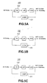
- the PLL circuit is generally indicated with a reference 100.
- the PLL circuit designed as shown in FIG. 5 selects a frequency division ratio in a frequency divider 101 according to the video signal format. More particularly, in the PLL circuit 100, the frequency division ratio is changed to 2200 as shown in FIG. 5A to generate a dot clock signal for display of the HD signal as an image, to 1716 as shown in FIG. 5B to generate a dot clock signal for display of the magnified NTSC vertical signal, and to 2280 as shown in FIG. 5C to generate a dot clock signal for display of the magnified-retrace HD horizontal signal.
- a select signal is supplied from outside to the frequency divider 101.
- the PLL circuit 100 For display of the HD signal, the PLL circuit 100 generates a dot clock signal of 74.25 MHz from the reference signal of 33.75 kHz. For display of the magnified NTSC vertical signal, the PLL circuit 100 generates a dot clock signal of 57.915 MHz from the reference signal. For display of the magnified-retrace HD horizontal signal, the PLL circuit 100 generates a dot clock signal of 76.95 MHz from the reference signal.
- the frequency divider 101 in the PLL circuit 100 shown in FIG. 5 has a high frequency division ratio, however, a dot clock signal generated as in the above is likely to have many jitters.
- the reference signal supplied to a phase comparator 102 has a frequency as low as 33.75 kHz. Therefore, the PLL circuit 100 cannot generate a reference signal by a crystal oscillator.
- a crystal oscillator is used to generate a signal of about 10 to 25 MHz, for example, in frequency and the signal is divided in frequency.
- the PLL circuit 100 is designed to generate a horizontal deflection frequency by further passing the dot clock signal through other frequency divider.
- the other frequency divider for generation of a signal having the horizontal deflection frequency has a frequency division ratio L which is determined based on a number of scanning lines in all horizontal directions.
- the frequency division ratio N will be any one of the above prime factor combinations (1) to (3).
- each of the expressions (1) to (3) is divided by a greatest common divisor to provide a frequency division ratio N.
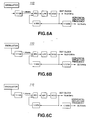
- FIG. 6 shows PLL circuits capable of providing frequency division ratios N for the above signals, respectively.
- the PLL circuit is generally indicated with a reference 110.
- the PLL circuits 110 are configured for the frequency division ratios N for the above signals, as shown in FIGS. 6A to 6C, respectively.
- the PLL circuits 110 shown in FIG. 6 have frequency division ratios L of 2200, 1716 and 2280 determined depending upon the number of vertical scanning lines and dot clock signals for the signal formats, respectively, to provide a horizontal deflection frequency of 33.75 kHz.
- the frequency division ratio used to generate a signal for supply to the phase comparator is still high and the reference signal supplied to the phase comparator is as low as 135 kHz, so that a dot clock signal thus generated will have many jitters. Therefore, the PLL circuit 110 shown in FIG. 6 is not advantageous when processing an HD signal for display of a high-definition image.
- FIG. 7 shows PLL circuits designed to provide frequency division ratios N of less than 100 and in which the reference frequency for supply to the phase comparator is in MHz.
- the PLL circuit is generally indicated with a reference 120.
- the PLL circuit 120 provides a frequency division ratio N of 55 for the HD signal as in FIG. 7A, a frequency division ratio N of 39 for the magnified NTSC vertical signal as in FIG. 7B, and a frequency division ratio N of 57 for the magnified-retrace HD horizontal signal as shown in FIG. 7C, respectively.
- the reference signal for generation of dot clock signals for the HD signal and magnified-retrace HD horizontal signal should have a frequency of 1.35 MHz, and that for generation of a dot clock signal for the magnified NTSC vertical signal should have a frequency of 1.485 MHz.
- Embodiments of the present invention can overcome or at least alleviate the above-mentioned drawbacks of the prior art by providing a clock generator adapted to generate jitter-less dot clock signals for video signals different in format from each other, an image displaying apparatus and method, in which the clock generator is used.
- Embodiments of the invention provide a clock generator adapted to different dot clock signals correspondingly to formats, respectively, of video signals to be displayed as images, comprising according to the present invention:
- the frequency division ratio setting means for setting the frequency division ratio for the frequency dividing means to less than a quotient resulted from division of a total number of horizontal pixels in each of the video signals by a greatest common divisor of the total number of horizontal pixels in the video signal having one format and total number of horizontal pixels in the video signal having the other format, is used to generate a dot clock signal for a video signal by changing the number of horizontal pixels in an image represented by the video signal to set a necessary frequency division ratio for the video signal.
- Embodiments of the invention provide an image displaying apparatus to display an image using a video signal converted according to a dot clock signal generated at a frequency division ratio set to less than a quotient resulted from division of a total number of horizontal pixels in each of the video signals by a greatest common divisor of the total number of horizontal pixels in the video signal having one format and total number of horizontal pixels in the video signal having the other format.
- Embodiments of the invention provide an image displaying method in which an image is displayed using a video signal converted according to a dot clock signal generated at a frequency division ratio set to less than a quotient resulted from division of a total number of horizontal pixels in each of the video signals by a greatest common divisor of the total number of horizontal pixels in the video signal having one format and total number of horizontal pixels in the video signal having the other format.
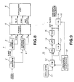
- the image displaying apparatus 1 comprises a Y/C separator 2 to which a video signal including a luminance signal (Y), color signal (C) and a sync signal.
- the Y/C separator 2 separates the video signal into the luminance signal (Y) and color signal (C), and provides the luminance signal (Y) to a sync signal separator 3 while providing the color signal (C) to a chroma decoder 4.
- the video signals for input to the Y/C separator 2 include a magnified NTSC vertical signal having a format as shown in FIG. 3, HD signal having a format as shown in FIG. 1, and a magnified-retrace HD horizontal signal having a format as shown in FIG. 4. As will be seen, these signals are different in format from each other.
- the image displaying apparatus 1 processes these input video signals according to their respective formats to display the images represented by the input video signals, respectively.
- the sync signal separator 3 is supplied with the luminance signal (Y) and sync signal from the Y/C separator 2, and separates the luminance signal (Y) and sync signal from each other.
- the sync signal is formed into a horizontal sync signal and a vertical sync signal.
- the sync signal separator 3 provides to a format converter 5 the horizontal and vertical sync signals along with the luminance signal (Y).
- the chroma decoder 4 generates chrominance signals (Cb) and (Cr) from the color signal (C) supplied from the Y/C separator 2, and provides the chrominance signals (Cb) and (Cr) to the format converter 5.
- the format converter 5 is provided to convert video signals having different formats, supplied to the Y/C separator 2 from outside. Thus the format converter 5 provide the luminance signal (Y), chrominance signals (Cb) and (Cr), and horizontal and vertical sync signals to a deflection/CRT unit 6. The format converter 5 generates a dot clock signal for delivery to the deflection/CRT unit 6.
- the format converter 5 incorporates a clock generator generally indicated with a reference 10 as shown in FIG. 9.
- the clock generator 10 incorporated in the format converter 5 functions as will be described below:
- the deflection/CRT unit 6 displays an image based on the luminance signal (Y), chrominance signals (Cb) and (Cr) supplied from the format converter 5. Specifically, the deflection/CRT unit 6 displays an image according to the format of its corresponding video signal using the horizontal and vertical sync signals and dot clock signal.
- the clock generator 10 included in the format converter 5 as shown in FIG. 9 includes a crystal oscillator 11 which applies a voltage to a crystal to generate a reference signal having about 10 to 25 MHz.
- the crystal oscillator 11 provides the reference signal thus generated to a frequency divider 12.
- the frequency divider 12 divides a reference signal supplied from the crystal oscillator 11 to provide a reference signal of 1.35 MHz, for example. More specifically, th frequency divider 12 will divide a reference signal supplied from the crystal oscillator 11, at a frequency division ratio M designated by a frequency division ratio controller 18, and provides the reference signal to a phase comparator 13.
- the phase comparator 13 is supplied with the reference signal from the frequency divider 12 and also with a signal from another frequency divider 17. Detecting a phase difference between the reference signal and the signal supplied from the frequency divider 17, the phase comparator 13 provides an LPF (low pass filter) 14 with a signal corresponding to the detected phase difference.
- LPF low pass filter
- the LPF 14 filters the signal corresponding to the phase difference, supplied from the phase comparator 13, and provides the filtered signal to a VCO (voltage control oscillator) 15.
- VCO voltage control oscillator
- the VCO 15 generates a dot clock signal based on the signal supplied from the LPF 14. More specifically, the VCO 15 generates a dot clock signal corresponding to the format of a video signal supplied to the Y/C separator 2 and provides it to the deflection/CRT unit 6. Also, the VCO 15 provides the generated dot clock signal to a still another frequency divider 16 and the frequency divider 17.
- the frequency divider 16 divides the frequency of the dot clock signal supplied from the VCO 15 at a frequency division ratio L designated by the frequency division ratio controller 18, to generate a signal of a horizontal deflection frequency and provides it to the deflection/CRT unit 6.
- the frequency divider 17 divides the frequency of the dot clock signal supplied from the VCO 15 at a frequency division ratio N designated by the frequency division ratio controller 18, to generate a signal of the same frequency, 1.35 MHz, for example, as that of the reference signal.
- the frequency divider 17 provides the signal to the phase comparator 13.
- the frequency division ratio controller 18 generates, based on the format of a video signal supplied to the Y/C separator 2, a control signal which is used to change the frequency division ratio of each of the frequency dividers 12, 16 and 17.
- the frequency division ratio controller 18 will set the frequency division ratio N to less than a quotient resulted from division of the total number of horizontal pixels in each of the video signals by a greatest common divisor of the total number of horizontal pixels in the video signal in consideration and that in a video signal having the other format.
- the frequency division ratio controller 18 will set the frequency division ratio N to 1720 by increasing the total number of 1716 horizontal pixels in the signal as shown in FIG. 1.
- the total numbers of horizontal pixels in the formats of the HD signal, magnified NTSC double-speed vertical signal and magnified-retrace HD horizontal signal are 1717, 2200 and 2280, respectively.
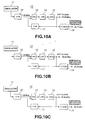
- the frequency division ratio controller 18 sets a frequency division ratio N of 55 (5*11) for generation of a dot clock signal for the HD signal as shown in FIG. 10A, and generates a dot clock signal having a frequency of 74.25 MHz. Also, the frequency division ratio controller 18 sets a frequency division ratio N of 43 for generation of a dot clock signal for the magnified NTSC double-speed vertical signal as shown in FIG. 10B, and generates a dot clock signal having a frequency of 58.05 MHz. Further, the frequency division ratio controller 18 sets a frequency division ratio N of 57 (3*19) for generation of a dot clock signal for the magnified-retrace HD horizontal signal as shown in FIG. 10C. In this case, the dot clock signal will have a frequency of 76.95 MHz.
- the frequency division ratio controller 18 will judge the format of the video signal and generates a control signal for changing the frequency division ratio of the frequency divider 17, to thereby control the frequency division ratios of the frequency dividers 12, 16 and 17.
- the frequency division ratio M of the frequency divider 12 is set to 1/16, whereby the reference signal of 21.6 MHz from the crystal oscillator 11 is supplied as a reference signal having a frequency of 1.35 MHz to the phase comparator 13, as will be seen from FIG. 10. Also, in the clock generator 10, the frequency division ratio N of the frequency divider 17 is changed for the format of each video signal correspondingly to a control signal supplied from the frequency division ratio controller 18 as shown in FIG. 10A to 10C, to thereby generate a dot clock signal.
- the frequency division ratio L of the frequency divider 16 is set by the frequency division ratio controller 18 by changing the number of vertical scanning lines, it is changed to 2200, 1720 or 2280 for the format of each video signal, thereby generating a signal having a horizontal deflection frequency of 33.75 kHz.
- the magnified NTSC double-speed vertical signal can be displayed with the dot clock signal of 58.05 MHz larger than the dot clock signal of 57.915 MHz in the prior art, the number of horizontal pixels displayed on the deflection/CRT unit 6 will be larger than the number of pixels displayed with the dot clock signal of 57.915 MHz.
- the clock generator 10 sets a frequency division ratio N for each of the input video signals by adjusting the total number of horizontal pixels for display of an image represented by each of the video signals and calculating the greatest common divisor of the numbers of pixels in the signal formats.
- the clock generator 10 permits to set a small frequency division ratio, so that a dot clock signal having less jitters can be generated.
- the clock generator 10 permits to set a reference signal having a frequency as high as 1.35 MHz for input to the phase comparator 13.
- the clock generator 10 can generate a dot clock signal using the common crystal oscillator 11 even when the image displaying apparatus according to the present invention is supplied with video signals having different formats.
- the frequency division ratio controller 18 may select an appropriate frequency division ratio L by changing the number of vertical scanning lines as in changing the total number of horizontal pixels.
- the image displaying apparatus 1 has been described concerning an example in which a plurality of video signals different in format from each other, such as the HD signal, magnified NTSC double-speed vertical signal and magnified-retrace HD horizontal signal, is supplied to the Y/C separator 2 and dot clock signals are generated for display of the video signals.
- the dot clock signals can be generated by changing the total number of horizontal pixels for a smaller frequency division ratio N even when video signals of different formats are processed for display.
- the image displaying apparatus is adapted such that a composite signal is supplied to the image display apparatus and subjected to the Y/C separation.
- the image displaying apparatus may be adapted so that a video signal compressed as in MPEG such as a digital TV broadcast signal is supplied to the apparatus and decoded as in MPEG before it is supplied to the format converter 5.
- the frequency division ratio controller provided in the clock generator according to the present invention controls the frequency division ratios of the frequency dividing means by changing the number of horizontal pixels of an image represented by an input video signal, calculating a dot clock signal and setting, based on the dot clock signal, a frequency division ratio at which a frequency division is made by the frequency dividers. Therefore, it is possible to generate a dot clock signal by setting a frequency division ratio through changing of the number of horizontal pixels of an image represented by the input video signal.
- the frequency division ratio for generation of a dot clock signal can be set low correspondingly to video signals having different formats, and thus it is possible to generate a dot clock signal having less jitters. Because of this clock generator, a common oscillator can be used for generation of dot clock signals for video signals having different formats, which contributes to a reduction of the manufacturing costs for the image displaying apparatus.
- the numbers of horizontal pixels in images represented by two or more video signals equal in horizontal scanning frequency to each other and different in number of horizontal pixels from each other are changed to set frequency division ratios, the frequency division ratios are used to generate dot clock signals, the video signals are converted according to the dot clock signals, and the converted video signals are used to display the images. So, it is possible to set smaller frequency division ratios for generation of dot clock signals for video signals having different formats and generate the dot clock signals having less jitters.
Landscapes
- Engineering & Computer Science (AREA)
- Multimedia (AREA)
- Signal Processing (AREA)
- Controls And Circuits For Display Device (AREA)
- Transforming Electric Information Into Light Information (AREA)
- Details Of Television Scanning (AREA)
- Stabilization Of Oscillater, Synchronisation, Frequency Synthesizers (AREA)
- Synchronizing For Television (AREA)
- Liquid Crystal Display Device Control (AREA)
Applications Claiming Priority (2)
| Application Number | Priority Date | Filing Date | Title |
|---|---|---|---|
| JP10323757A JP2000152121A (ja) | 1998-11-13 | 1998-11-13 | クロック生成回路、画像表示装置及び方法 |
| JP32375798 | 1998-11-13 |
Publications (2)
| Publication Number | Publication Date |
|---|---|
| EP1001616A2 true EP1001616A2 (de) | 2000-05-17 |
| EP1001616A3 EP1001616A3 (de) | 2002-07-10 |
Family
ID=18158298
Family Applications (1)
| Application Number | Title | Priority Date | Filing Date |
|---|---|---|---|
| EP99308921A Withdrawn EP1001616A3 (de) | 1998-11-13 | 1999-11-09 | Taktgenerator sowie Verfahren und Vorrichtung zur Bildanzeige |
Country Status (5)
| Country | Link |
|---|---|
| US (1) | US6515708B1 (de) |
| EP (1) | EP1001616A3 (de) |
| JP (1) | JP2000152121A (de) |
| KR (1) | KR100662219B1 (de) |
| AU (1) | AU5940999A (de) |
Cited By (4)
| Publication number | Priority date | Publication date | Assignee | Title |
|---|---|---|---|---|
| WO2008099948A1 (en) * | 2007-02-08 | 2008-08-21 | Nec Display Solutions, Ltd. | Image display apparatus and frequency adjustment method thereof |
| WO2009072015A3 (en) * | 2007-12-05 | 2009-10-15 | Arcelik Anonim Sirketi | A receiver and a control method |
| CN101312035B (zh) * | 2007-05-07 | 2012-01-11 | 瑞萨电子株式会社 | 点时钟产生电路、半导体器件以及点时钟产生方法 |
| WO2012100946A2 (en) | 2011-01-27 | 2012-08-02 | Deutsche Telekom Ag | Method for the use of a gsm/umts mobile communication network by a user equipment attached to a core network of an evolved packet system (eps) mobile communication network |
Families Citing this family (10)
| Publication number | Priority date | Publication date | Assignee | Title |
|---|---|---|---|---|
| JP2001094823A (ja) * | 1999-09-22 | 2001-04-06 | Sony Corp | マルチスキャン対応水平同期信号生成システム |
| US7032121B2 (en) * | 2002-01-10 | 2006-04-18 | Hatteras Networks | System for deriving desired output frequency by successively dividing clock signal frequency by ratios obtained by dividing clock signal frequency by common divisor and specific integer |
| KR100907100B1 (ko) * | 2003-03-29 | 2009-07-09 | 엘아이지넥스원 주식회사 | 영상 수평 동기신호에 대한 도트 클록신호 발생장치 |
| KR100502932B1 (ko) * | 2003-08-01 | 2005-07-21 | 삼성에스디아이 주식회사 | 주파수 변환 장치 및 이를 이용한 플라즈마 디스플레이패널의 구동 장치 |
| JP4572144B2 (ja) * | 2005-07-06 | 2010-10-27 | Necディスプレイソリューションズ株式会社 | 表示パネル駆動装置および表示パネル駆動方法 |
| JP4972907B2 (ja) * | 2005-10-12 | 2012-07-11 | パナソニック株式会社 | ドットクロック再生回路 |
| KR100790984B1 (ko) | 2006-03-03 | 2008-01-02 | 삼성전자주식회사 | Dot 클럭 신호의 주파수에 관계없이 일정한 주파수의시스템 클럭 신호를 생성하는 디스플레이용 구동 집적회로및 시스템 클럭 신호 생성 방법 |
| US8554815B1 (en) * | 2006-11-09 | 2013-10-08 | Applied Micro Circuits Corporation | Frequency generation using a single reference clock and a primitive ratio of integers |
| WO2013150698A1 (ja) * | 2012-04-03 | 2013-10-10 | パナソニック株式会社 | 映像信号送信装置及び受信装置 |
| US10595075B2 (en) * | 2017-08-04 | 2020-03-17 | Disney Enterprises, Inc. | Automatic timing of production devices in an internet protocol environment |
Family Cites Families (14)
| Publication number | Priority date | Publication date | Assignee | Title |
|---|---|---|---|---|
| US3559092A (en) * | 1968-09-09 | 1971-01-26 | Tektronix Inc | Frequency dividing system |
| JPH05207326A (ja) * | 1992-01-28 | 1993-08-13 | Matsushita Electric Ind Co Ltd | 水平圧縮pll回路 |
| JP3307750B2 (ja) * | 1993-12-28 | 2002-07-24 | キヤノン株式会社 | 表示制御装置 |
| JPH07210670A (ja) * | 1994-01-21 | 1995-08-11 | Fuji Xerox Co Ltd | 画像処理装置 |
| JPH08154183A (ja) * | 1994-11-28 | 1996-06-11 | Sanyo Electric Co Ltd | 映像縮小方法 |
| KR0172486B1 (ko) * | 1995-01-16 | 1999-03-20 | 김광호 | 샘플링율 변환방법 및 그 장치 |
| US6097440A (en) * | 1995-11-17 | 2000-08-01 | Sony Corporation | Synchronous processing device |
| KR100194922B1 (ko) * | 1996-04-29 | 1999-06-15 | 윤종용 | 화면비 변환장치 |
| JP4022935B2 (ja) * | 1997-01-21 | 2007-12-19 | ソニー株式会社 | 画像処理装置および処理方法 |
| US5739867A (en) * | 1997-02-24 | 1998-04-14 | Paradise Electronics, Inc. | Method and apparatus for upscaling an image in both horizontal and vertical directions |
| KR100238673B1 (ko) * | 1997-05-30 | 2000-01-15 | 윤종용 | 고선명 텔레비젼 수상기의 모니터 출력장치 |
| US5977836A (en) * | 1997-06-16 | 1999-11-02 | Ati International Srl | Method and apparatus for controlling an output frequency of a phase locked loop |
| JP3638762B2 (ja) * | 1997-09-03 | 2005-04-13 | 株式会社ルネサステクノロジ | 同期信号生成装置およびそれを用いたフィールド判定装置 |
| US6069666A (en) * | 1998-03-13 | 2000-05-30 | Sarnoff Corporation | Broadcast studio synchronization distribution system and method |
-
1998
- 1998-11-13 JP JP10323757A patent/JP2000152121A/ja not_active Withdrawn
-
1999
- 1999-11-09 EP EP99308921A patent/EP1001616A3/de not_active Withdrawn
- 1999-11-12 KR KR1019990050142A patent/KR100662219B1/ko not_active Expired - Fee Related
- 1999-11-12 US US09/439,592 patent/US6515708B1/en not_active Expired - Fee Related
- 1999-11-12 AU AU59409/99A patent/AU5940999A/en not_active Abandoned
Cited By (6)
| Publication number | Priority date | Publication date | Assignee | Title |
|---|---|---|---|---|
| WO2008099948A1 (en) * | 2007-02-08 | 2008-08-21 | Nec Display Solutions, Ltd. | Image display apparatus and frequency adjustment method thereof |
| CN101542586B (zh) * | 2007-02-08 | 2011-12-28 | Nec显示器解决方案株式会社 | 图像显示装置及其频率调整方法 |
| US8310431B2 (en) | 2007-02-08 | 2012-11-13 | Nec Display Solutions, Ltd. | Image display apparatus and frequency adjustment method thereof |
| CN101312035B (zh) * | 2007-05-07 | 2012-01-11 | 瑞萨电子株式会社 | 点时钟产生电路、半导体器件以及点时钟产生方法 |
| WO2009072015A3 (en) * | 2007-12-05 | 2009-10-15 | Arcelik Anonim Sirketi | A receiver and a control method |
| WO2012100946A2 (en) | 2011-01-27 | 2012-08-02 | Deutsche Telekom Ag | Method for the use of a gsm/umts mobile communication network by a user equipment attached to a core network of an evolved packet system (eps) mobile communication network |
Also Published As
| Publication number | Publication date |
|---|---|
| US6515708B1 (en) | 2003-02-04 |
| EP1001616A3 (de) | 2002-07-10 |
| JP2000152121A (ja) | 2000-05-30 |
| KR20000035436A (ko) | 2000-06-26 |
| KR100662219B1 (ko) | 2007-01-02 |
| AU5940999A (en) | 2000-05-18 |
Similar Documents
| Publication | Publication Date | Title |
|---|---|---|
| US5534934A (en) | Television receiver capable of enlarging and compressing image | |
| KR100195358B1 (ko) | 라인 메모리 및 제어 시스템 | |
| US5134479A (en) | NTSC high resolution television converting apparatus for converting television signals of an NTSC system into high resolution television signals | |
| US6441860B1 (en) | Video signal processing apparatus | |
| EP1001616A2 (de) | Taktgenerator sowie Verfahren und Vorrichtung zur Bildanzeige | |
| US6927801B2 (en) | Video signal processing apparatus and video displaying apparatus | |
| WO1998020670A2 (en) | System for converting computer graphics to television format with scaling requiring no frame buffers | |
| US7486334B2 (en) | Image display system | |
| EP1727121B1 (de) | Anzeigevorrichtung und Steuerverfahren dafür | |
| US6532042B1 (en) | Clock supply device for use in digital video apparatus | |
| JP2914140B2 (ja) | テレビジョン受像装置 | |
| EP0185503A2 (de) | Digitale Abtastungsumwandler | |
| US5912714A (en) | Clock generator for a video signal processing apparatus | |
| US7327401B2 (en) | Display synchronization signal generation apparatus and method in analog video signal receiver | |
| JP3638443B2 (ja) | ディジタル放送用テレビジョン受信機 | |
| JP3291190B2 (ja) | Tv受像機の複数の多画面準動画ディスプレイ装置 | |
| JP2832789B2 (ja) | テレビジョン映像信号用タイミング信号発生回路及び映像信号処理装置 | |
| JP2006227442A (ja) | 映像信号処理装置、及び該装置を備えた映像表示装置 | |
| JPH09214998A (ja) | 同期信号処理回路 | |
| JPS6281892A (ja) | コンポジツト信号発生方法 | |
| JPH05207395A (ja) | 映像表示装置 | |
| JPH06319090A (ja) | 子画面発生装置 | |
| JPH0998354A (ja) | デジタルテレビジョン信号処理装置 | |
| JPH10215416A (ja) | 映像信号処理装置 | |
| JPH0856294A (ja) | 暗部検出装置 |
Legal Events
| Date | Code | Title | Description |
|---|---|---|---|
| PUAI | Public reference made under article 153(3) epc to a published international application that has entered the european phase |
Free format text: ORIGINAL CODE: 0009012 |
|
| AK | Designated contracting states |
Kind code of ref document: A2 Designated state(s): AT BE CH CY DE DK ES FI FR GB GR IE IT LI LU MC NL PT SE |
|
| AX | Request for extension of the european patent |
Free format text: AL;LT;LV;MK;RO;SI |
|
| PUAL | Search report despatched |
Free format text: ORIGINAL CODE: 0009013 |
|
| AK | Designated contracting states |
Kind code of ref document: A3 Designated state(s): AT BE CH CY DE DK ES FI FR GB GR IE IT LI LU MC NL PT SE |
|
| AX | Request for extension of the european patent |
Free format text: AL;LT;LV;MK;RO;SI |
|
| RIC1 | Information provided on ipc code assigned before grant |
Free format text: 7H 04N 7/01 A, 7G 06F 1/08 B, 7H 04N 5/12 B, 7H 04N 5/46 B, 7H 03L 7/06 B |
|
| AKX | Designation fees paid | ||
| REG | Reference to a national code |
Ref country code: DE Ref legal event code: 8566 |
|
| STAA | Information on the status of an ep patent application or granted ep patent |
Free format text: STATUS: THE APPLICATION IS DEEMED TO BE WITHDRAWN |
|
| 18D | Application deemed to be withdrawn |
Effective date: 20030111 |