EP1001653A2 - Haut-parleur piezoélectrique - Google Patents
Haut-parleur piezoélectrique Download PDFInfo
- Publication number
- EP1001653A2 EP1001653A2 EP99120895A EP99120895A EP1001653A2 EP 1001653 A2 EP1001653 A2 EP 1001653A2 EP 99120895 A EP99120895 A EP 99120895A EP 99120895 A EP99120895 A EP 99120895A EP 1001653 A2 EP1001653 A2 EP 1001653A2
- Authority
- EP
- European Patent Office
- Prior art keywords
- piezoelectric
- visco
- elastic member
- diaphragm
- piezoelectric vibrator
- Prior art date
- Legal status (The legal status is an assumption and is not a legal conclusion. Google has not performed a legal analysis and makes no representation as to the accuracy of the status listed.)
- Granted
Links
Images
















Classifications
-
- H—ELECTRICITY
- H04—ELECTRIC COMMUNICATION TECHNIQUE
- H04R—LOUDSPEAKERS, MICROPHONES, GRAMOPHONE PICK-UPS OR LIKE ACOUSTIC ELECTROMECHANICAL TRANSDUCERS; ELECTRIC HEARING AIDS; PUBLIC ADDRESS SYSTEMS
- H04R17/00—Piezoelectric transducers; Electrostrictive transducers
- H04R17/005—Piezoelectric transducers; Electrostrictive transducers using a piezoelectric polymer
Definitions
- the present invention relates to a piezoelectric loudspeaker having flat reproduced sound volume characteristics in a wide range of frequencies.
- the visco-elastic member includes first and second visco-elastic members which are provided on opposite sides of the piezoelectric vibrator.
- the piezoelectric loudspeaker further includes an element provided in a central portion of the visco-elastic member, at least one of specific gravity and elastic modulus of the element being larger than specific gravity and/or elastic modulus of the visco-elastic member.
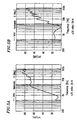
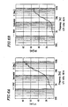
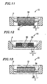
- the piezoelectric loudspeaker includes : a piezoelectric vibrator including a diaphragm and a piezoelectric member provided on at least one face of the diaphragm, the diaphragm being vibrated by the piezoelectric member; a frame for supporting the piezoelectric vibrator; and a visco-elastic member provided on at least one face of the piezoelectric vibrator, wherein the visco-elastic member is disposed in a substantial center of the piezoelectric vibrator, wherein the visco-elastic member has a bottom face area which accounts for about 11% to about 80% of a bottom face area of the diaphragm, and wherein the bottom face area of the visco-elastic member is equal to or greater than the bottom face area of the piezoelectric member, and a diameter of the visco-elastic member is smaller than the inner diameter of the frame.
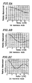
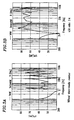
- the visco-elastic member 5A is attached to at least one side of the piezoelectric vibrator 3 so that the bottom face area of the visco-elastic member 5A accounts for about 11% to about 80% of the bottom face area of the diaphragm 1 .
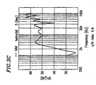
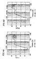
- the piezoelectric loudspeaker 10 operates so as to prevent the occurrence of a plurality of resonance modes. Thus, flat sound volume-frequency characteristics can be attained.
- the frame 4B used to affix or support the piezoelectric vibrator 3 has a horn-like configuration such that its opening has gradually increasing cross-sectional area (taken along a direction perpendicular to the plane of Figure 16 ) away from the diaphragm 1 and toward the final opening (shown at the uppermost portion of Figure 16 ).
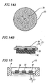
- the visco-elastic member 5D has a conical configuration which has largest cross-sectional area where it is in contact with the piezoelectric vibrator 3 and gradually decreases in cross-sectional area away from the piezoelectric vibrator 3 .
- the visco-elastic member 5D acts to control the resonance modes of the piezoelectric vibrator 3 .
- FIG 17 is a cross-sectional view showing a piezoelectric loudspeaker 10 according to Example 11 of the present invention.
- the piezoelectric loudspeaker 10 includes a diaphragm 1 , a thin piezoelectric member 2B , a frame 4B , and a visco-elastic member 5E .
- a piezoelectric vibrator 3 is composed of the diaphragm 1 and the thin piezoelectric member 2B attached thereto.
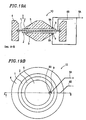
- visco-elastic members 5E , 5F , 5D , and 5E shown in Figures 14A , 14B , 15 , 16 , and 17 are illustrated as being attached to only one side of the respective piezoelectric vibrator 3 , they may be attached to opposite sides of the respective piezoelectric vibrator 3 for enhanced resonance control.
- each piezoelectric loudspeaker 10 shares the same basic structure as that described in the foregoing examples (e.g., the piezoelectric vibrator 3 being composed of a diaphragm and a thin piezoelectric member attached thereto). Accordingly, for conciseness, detailed description of such elements is omitted in the descriptions of the following examples.
- the piezoelectric loudspeaker 10 As an electric input is applied across lead wires 6A and 6B , the piezoelectric vibrator 3 vibrates in a bending mode owing to the action of a piezoelectric member 2 attached to a diaphragm 1 . Although the diaphragm 1 and the piezoelectric member 2 have very small internal losses and a large resonance peak Q at their respective resonance points, the visco-elastic members 5 which are attached to the piezoelectric vibrator 3 control its Q value.
- the piezoelectric vibrator 3 may have a large amplitude in the central portion even with the visco-elastic members 5 attached thereto, possibly causing the peeling of the piezoelectric member 2 from the diaphragm 1 during periods of excessive amplitude. Accordingly, the elements 7 , at least one of whose specific gravity and elastic modulus is larger than the specific gravity and/or elastic modulus of the visco-elastic member 5 , are used to control the amplitude.
- the elements 7 serve to minimize the excessive amplitude occurring in the central portion of the piezoelectric vibrator 3 while maintaining flat reproduced sound volume-frequency characteristics provided by the damping effect of the visco-elastic members 5 .
- the piezoelectric loudspeaker 10 attains an improved withstand input level without deterioration in the reproduced sound volume-frequency characteristics.
- the piezoelectric loudspeaker 10 When an electric input is applied across lead wires 6A and 6B , the piezoelectric vibrator 3 vibrates in a bending mode owing to the action of a piezoelectric member 2 attached to a diaphragm 1 . Although the diaphragm 1 and the piezoelectric member 2 have very small internal losses and a large resonance peak Q at their respective resonance points, the visco-elastic members 5 which are attached to the piezoelectric vibrator 3 control its Q value.
- the positive lead wire 6A is typically coupled to the piezoelectric member 2 by use of solder or adhesive, which may form a bump at each junction portion 9 between the positive lead wire 6A and the piezoelectric member 2
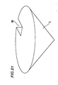
- the notches 8A allow the visco-elastic members 5 to be in close contact with the piezoelectric vibrator 3 in much a manner that the visco-elastic members 5 do not entirely cover the junction portions 9 .
- the damping effect on the piezoelectric vibrator 3 provided by the visco-elastic members 5 can be fully realized, thereby providing stable, flat reproduced sound volume-frequency characteristics without substantial fluctuation.
- Figure 22 is a cross-sectional view showing a piezoelectric loudspeaker 10 according to Example 14 of the present invention. As shown, a support element 22 is provided at the substantial center of a piezoelectric vibrator 3 . The support element 22 is at least partially composed of a conductive material, and also acts as a positive (+) electrode.
- the operation of the piezoelectric loudspeaker 10 will now be described.
- the input electric signal is transmitted to a piezoelectric member 2 via the partially conductive support element 22 , causing the piezoelectric vibrator 3 to vibrate in a bending mode.
- a visco-elastic member 5 attached to the piezoelectric vibrator 3 controls the resonance peak Q at the resonance points of the piezoelectric vibrator 3 , thereby providing flat reproduced sound volume-frequency characteristics.
- the support element 22 supports the piezoelectric vibrator 3 at its substantial center, the excessive amplitude which may occur in the central portion of the piezoelectric vibrator 3 responsive to a large electric input is minimized, thereby improving the withstand input level; this effect is similar to that provided by Example 13.
- the conductive support element 22 doubles as a positive electrode for the piezoelectric vibrator 3 , there is no need for a separate positive lead wire. As a result, the malfunctioning possibilities due to severance or entanglement of lead wires are minimized. The omission of a separate positive lead wire also makes for improved production yield and improved appearances.
- the piezoelectric loudspeaker 10 can also be implemented without a visco-elastic member 5 and still minimize the excessive amplitude occurring in the central portion of the piezoelectric vibrator 3 .
- the support element 22 does not need to be conductive; in the case where the support element 22 is non-conductive, a positive lead wire will be provided.
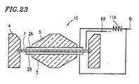
- Figure 23 is a cross-sectional view showing a piezoelectric loudspeaker 10 according to Example 15 of the present invention.
- piezoelectric member 2A and 2B are provided on an upper face and a lower face, respectively, of a diaphragm 1 .
- An electrical resistance 11A is inserted between the piezoelectric member 2A and a positive (+) lead wire 6A .
- the operation of the piezoelectric loudspeaker 10 according to the present example will now be described. As shown in the graph of Figure 24 , due to the electrical resistance 11A inserted between the piezoelectric member 2A and the positive lead wire 6A , the electrical impedance of the piezoelectric loudspeaker 10 as seen from the lead wires 6A and 6B is shifted upward in the higher frequency band as compared to that of the same piezoelectric loudspeaker 10 which lacks the electrical resistance 11A .
- visco-elastic members 5 are illustrated in Figure 23 , the present example can also be implemented without visco-elastic members 5 .
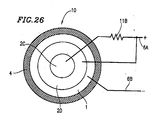
- FIG 26 is a schematic plan view illustrating a piezoelectric loudspeaker 10 according to Example 16 of the present invention.
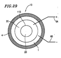
- the piezoelectric loudspeaker 10 includes a piezoelectric member 2 which is split in two sections 2C and 2D , with an electrical resistance 11B inserted between the piezoelectric section 2C and a positive lead wire 6A .
- a low pass filter is created which includes the electrical resistance 11B inserted between the piezoelectric section 2C and the positive lead wire 6A ; this effect is similar to that provided by Example 15 .
- the other piezoelectric section 2D operates as a normal piezoelectric loudspeaker (i.e., without low-pass filtering capabilities).
- the piezoelectric sections 2C and 2D may provide sound volume characteristics as exemplified by curves A and B , respectively, in the graph of Figure 27 . Accordingly, the overall characteristics of the piezoelectric loudspeaker 10 is equal to a sum of the characteristics A and B in Figure 27 . Thus, the reproducible frequency range of the piezoelectric loudspeaker 10 can be expanded.
- Figures 26 , 28 , and 29 do not illustrate any visco-elastic members, it is also applicable to provide a visco-elastic member 5 on the piezoelectric loudspeaker 10 according to Example 16 of the invention.
- the aforementioned piezoelectric member 2 composed of discrete piezoelectric sections may be implemented as a combination of annular piezoelectric members or stacked disk-shaped piezoelectric members.
- a plurality of electrical resistance elements, or a plurality of conductive elements to serve as electrical resistance, may be employed so long as they are capable of applying different voltages to the plurality of piezoelectric sections.
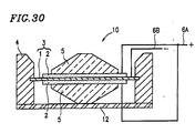
- FIG 30 is a cross-sectional view showing a piezoelectric loudspeaker 10 according to Example 17 of the present invention.
- the piezoelectric loudspeaker 10 includes a plate 12 for interconnecting a frame 4 to one of a pair of visco-elastic members 5 .
- a piezoelectric vibrator 3 vibrates in a bending mode.
- a diaphragm 1 and a piezoelectric member 2 have very small internal losses and a large resonance peak Q at their respective resonance points, the visco-elastic members 5 which are attached to the piezoelectric vibrator 3 control its Q value.
- the central portion of the piezoelectric vibrator 3 (at which the piezoelectric vibrator 3 may be adhered to the visco-elastic member 5 ) is prevented from having an excessive amplitude.
- the plate 12 for interconnecting one of the visco-elastic members 5 to frame 4 serves to minimize the excessive amplitude occurring in the central portion of the piezoelectric vibrator 3 while maintaining flat reproduced sound volume-frequency characteristics due to the damping effect provided by the visco-elastic members 5 .
- the piezoelectric loudspeaker 10 attains an improved withstand input level.
- the lowest resonance frequency of a given loudspeaker which defines the lowest reproducible frequency of the loudspeaker, is determined by the mass of a diaphragm 1 and a spring factor against the diaphragm. Therefore, it is possible to adjust the lowest resonance frequency of the piezoelectric loudspeaker 10 by employing the physical volume within the enclosed space as a parameter in the loudspeaker design.
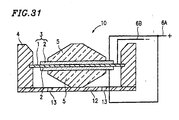
- through-holes 13 in the plate 12 for allowing air passage, as shown in Figure 31 .
- the through-holes 13 act as acoustic resistance against the piezoelectric vibrator 3 .
- Such through-holes 13 may be utilized to enhance the damping effects beyond what is attained by the visco-elastic members 5 , thereby improving the flatness of the sound volume characteristics.
- the plate 12 also serves as a means for protecting the piezoelectric vibrator 3 from extrinsic impacts or shocks, and/or preventing foreign articles from straying into the speaker system.
- an electrode 14 which is affixed to the plate 12 and penetrates the visco-elastic member 5 so as to achieve electrical contact with the piezoelectric vibrator 3 , the electrode 14 serving as an electric input terminal. Since this eliminates the need for at least one lead wire, malfunctioning possibilities due to severance or entanglement of lead wires are minimized. A reduced number of lead wires also makes for improved production yield and improved appearances.
- the piezoelectric vibrators 3 shown in Figures 30 to 33 are of a bimorph type composed essentially of a diaphragm 1 and piezoelectric members 2 attached to opposite sides thereof.
- piezoelectric vibrators 3 of a monomorph type composed essentially of a diaphragm 1 and a piezoelectric member 2 attached to one side thereof; in this case, the positive lead wire 6A for the upper piezoelectric member 2 can be omitted, thereby making for much improved production yield and appearances.
- the above example illustrates two visco-elastic members 5 provided on opposite sides of the piezoelectric vibrator 3 , it is also applicable to provide one visco-elastic member 5 on only one side of the piezoelectric vibrator 3 .
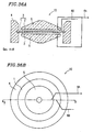
- Figures 34A and 34B are a cross-sectional view and a plan view, respectively, showing a piezoelectric loudspeaker 10 according to Example 18 of the present invention.
- a diaphragm 1 has a through-hole 15 , through which one of positive (+) lead wires 6A is coupled to a piezoelectric vibrator 3 .
- the lead wires can be gathered on the back side (shown as the lower side in Figure 34A ), which makes for improved appearances. Less complex wiring also leads to improved production yield.
- Figures 35A and 35B are a cross-sectional view and a plan view, respectively, showing a piezoelectric loudspeaker 10 according to Example 19 of the present invention.
- a conductive electrode 16 is provided which is affixed to a frame 4 and penetrates the visco-elastic member 5 so as to achieve electrical contact with a piezoelectric vibrator 3 .
- a cover 17 is provided for connecting the electrode 16 to the frame 4 .
- the cover 17 serves as a means for protecting the piezoelectric vibrator 3 and the visco-elastic members 5 from being damaged by extrinsic impacts or shocks. Furthermore, the cover 17 serves as an acoustic equalizer for the soundwaves which are generated by the vibration of the piezoelectric vibrator 3 , thereby broadening the directivity in the higher frequency range and providing flatter reproduction characteristics.
- cover 17 illustrated in Figures 35A and 35B is only provided on one side of the piezoelectric vibrator 3 , it is also possible to provide a cover 17 on each side of the piezoelectric vibrator 3 . In this case, separate positive lead wires 6A would not be required.
- the cover 17 By at least partially constructing the cover 17 from a conductive material in such a manner that the cover 17 is insulated from a diaphragm 1 (to which a negative (-) electrical input is applied), all of the electric input terminals can be provided in the vicinity of the junction between the cover 17 and the frame 4 . This makes for improved appearances and facility of use, and also substantially eliminates malfunctioning possibilities due to severance or entanglement of lead wires.
- cover 17 as illustrated in Figure 35B includes three fans, any number of fans may be provided in accordance with the desired acoustic equalizer configuration.
- Figures 36A and 36B are a cross-sectional view and a plan view, respectively, showing a piezoelectric loudspeaker 10 according to Example 20 of the present invention.
- visco-elastic members 5 provided upon a piezoelectric member 2 each have a bottom face area which is equal to or greater than the bottom face area of the piezoelectric member 2 and yet small enough to fit within the inner diameter of the frame 4 (i.e., the diameter of the visco-elastic member 5 is smaller than the inner diameter of the frame 4 ).
- the visco-elastic members 5 serve as means for protecting the piezoelectric member 2 from extrinsic impacts or shocks, and/or preventing foreign articles from straying into the speaker system to cause peeling of, or inflict damage to, the piezoelectric member 2 .
- FIG 37 is a cross-sectional view showing a piezoelectric loudspeaker 10 according to Example 21 of the present invention.
- a negative (-) electric terminal 18 which is composed of a conductive material is provided in a portion of a frame 4 so as to be in electrical contact with a diaphragm 1 .
- the negative electric terminal 18 eliminates the need for a separate negative lead wire, thereby eliminating malfunctioning possibilities due to severance or entanglement of lead wires. Since the negative electric terminal is constructed simply by affixing the diaphragm 1 to the frame 4 , the number of manufacture steps can be reduced, thereby facilitating ease of assembly.
- the appearances of the piezoelectric loudspeaker 10 can also be improved according to the present example.
- any of the structures shown in Figures 22 , 32 , 33 , 35A and 35B , in which there is no need for at least one of the positive lead wires, can suitably incorporate the negative electric terminal 18 according to the present example for the aforementioned effects. It is also possible to provide a positive electric terminal(s) within the frame 4 in addition to the negative electric terminal 18 .
- two visco-elastic members 5 are illustrated as being provided on opposite sides of the piezoelectric vibrator 3 , one visco-elastic member 5 may be provided on only one side of the piezoelectric vibrator 3 .
- the configuration of the diaphragm, piezoelectric member, frame, and visco-elastic member of the piezoelectric loudspeaker 10 according to the present invention may be disk-like or annular. However, they may alternatively have polygonal shapes. It is also possible that some of these elements have one shape while others have another. By appropriately selecting the configurations, materials, positions, etc. for the respective constituent elements of the piezoelectric loudspeaker 10 according to the present invention, it is possible to design a loudspeaker which provides the desired characteristics, good space economy, and good appearances.
- a visco-elastic member is attached to a central portion of a piezoelectric vibrator which is composed essentially of a diaphragm and a piezoelectric member(s) attached to one side or both sides of the diaphragm, such that the bottom face area of the visco-elastic member accounts for about 11% to about 80% of the bottom face area of the diaphragm.
- the present invention provides the outstanding advantages, such as ability to control the resonance modes of a piezoelectric vibrator without allowing the vibratory energy to be leaked to a supporting frame or the like, thereby realizing a piezoelectric loudspeaker which has a high sound volume level and flat reproduced sound volume-frequency characteristics.
- the excessive amplitude occurring in the central portion of the piezoelectric vibrator can be minimized, thereby providing for improved withstand input level. This results in a reduced number of lead wires, which reduces malfunctioning possibilities and improves production yield.
- a low-pass filter By inserting an electrical resistance between a piezoelectric vibrator and at least one lead wire, a low-pass filter can be constructed for controlling the reproduction band width.
- a low-pass filter By dividing a piezoelectric vibrator into concentric sections or vertically split sections, and inserting an electrical resistance or a conductive material having high resistance between such sections, a low-pass filter can be constructed in the split piezoelectric vibrator so that the piezoelectric vibrator operates as a composite loudspeaker. As a result, the reproduction band width can be expanded.
- the excessive amplitude in the central portion of the piezoelectric vibrator can be minimized, and an acoustic element can be constructed within the space between the plate, the piezoelectric vibrator, and the frame, thereby enabling adjustment of sound volume characteristics.
- the sound volume characteristics can be improved, the piezoelectric loudspeaker can be protected from extrinsic impacts or shocks, and a reduced number of lead wires decreases malfunctioning possibilities and improves the appearances of the piezoelectric loudspeaker.
- the visco-elastic member By ensuring that the visco-elastic member has a bottom face area which is equal to or greater than the bottom face area of the piezoelectric member and yet small enough to fit within the inner diameter of the frame, the visco-elastic member can serve as a means for protecting the piezoelectric member.
- a negative lead wire can be omitted, thereby making for improved appearances and production facility and substantially eliminating malfunctioning possibilities.
- member e.g., "visco-elastic member”, “piezoelectric member”, etc.
- a “member” refers to any piece or amount of material taking a definite or indefinite shape such that the “member” satisfies the aforementioned dimensional requirements as appropriate.
Landscapes
- Physics & Mathematics (AREA)
- Engineering & Computer Science (AREA)
- Acoustics & Sound (AREA)
- Signal Processing (AREA)
- Piezo-Electric Transducers For Audible Bands (AREA)
Applications Claiming Priority (6)
| Application Number | Priority Date | Filing Date | Title |
|---|---|---|---|
| JP31177098 | 1998-11-02 | ||
| JP31177098 | 1998-11-02 | ||
| JP25441699 | 1999-09-08 | ||
| JP11254416A JP2000201399A (ja) | 1998-11-02 | 1999-09-08 | 圧電スピ―カ |
| JP25857799A JP2001086592A (ja) | 1999-09-13 | 1999-09-13 | 圧電型スピーカ |
| JP25857799 | 1999-09-13 |
Publications (3)
| Publication Number | Publication Date |
|---|---|
| EP1001653A2 true EP1001653A2 (fr) | 2000-05-17 |
| EP1001653A3 EP1001653A3 (fr) | 2001-11-14 |
| EP1001653B1 EP1001653B1 (fr) | 2008-07-16 |
Family
ID=27334331
Family Applications (1)
| Application Number | Title | Priority Date | Filing Date |
|---|---|---|---|
| EP99120895A Expired - Lifetime EP1001653B1 (fr) | 1998-11-02 | 1999-10-28 | Haut-parleur piezoélectrique |
Country Status (3)
| Country | Link |
|---|---|
| US (1) | US6747395B1 (fr) |
| EP (1) | EP1001653B1 (fr) |
| DE (1) | DE69939096D1 (fr) |
Cited By (2)
| Publication number | Priority date | Publication date | Assignee | Title |
|---|---|---|---|---|
| CN103181194A (zh) * | 2010-11-01 | 2013-06-26 | Nec卡西欧移动通信株式会社 | 电子设备 |
| KR20160015348A (ko) * | 2016-01-22 | 2016-02-12 | 한국전자통신연구원 | 압전 스피커 |
Families Citing this family (17)
| Publication number | Priority date | Publication date | Assignee | Title |
|---|---|---|---|---|
| US8334637B2 (en) * | 2006-09-18 | 2012-12-18 | Liposonix, Inc. | Transducer with shield |
| US7652411B2 (en) * | 2006-09-18 | 2010-01-26 | Medicis Technologies Corporation | Transducer with shield |
| CN101611538A (zh) * | 2007-01-12 | 2009-12-23 | 日本电气株式会社 | 压电致动器和电子装置 |
| JP5279726B2 (ja) * | 2007-12-19 | 2013-09-04 | パナソニック株式会社 | 圧電型音響変換器 |
| CN101820567A (zh) * | 2009-02-27 | 2010-09-01 | 宁波升亚电子有限公司 | 扬声器及其制造方法 |
| KR101622632B1 (ko) * | 2009-08-26 | 2016-05-20 | 엘지전자 주식회사 | 이동 단말기 |
| JP5409925B2 (ja) * | 2011-09-30 | 2014-02-05 | 京セラ株式会社 | 圧電振動装置およびそれを用いた携帯端末 |
| US9445200B2 (en) * | 2012-05-14 | 2016-09-13 | Electronics And Telecommunications Research Institute | Piezoelectric speaker having weight and method of producing the same |
| KR101630353B1 (ko) * | 2012-05-14 | 2016-06-24 | 한국전자통신연구원 | 질량체를 가진 압전 스피커 및 그 제조 방법 |
| JP6117945B2 (ja) * | 2014-01-11 | 2017-04-19 | 京セラ株式会社 | 音響発生器,音響発生装置,電子機器 |
| US9848268B2 (en) * | 2014-01-11 | 2017-12-19 | Kyocera Corporation | Acoustic generator, acoustic generation device, and electronic apparatus |
| US11190881B2 (en) * | 2019-06-04 | 2021-11-30 | uBeam Inc. | Piezoelectric transducer |
| CN110381428B (zh) * | 2019-08-30 | 2025-01-07 | 湖南捷力泰科技有限公司 | 新型压电扬声器 |
| JP7148481B2 (ja) | 2019-12-04 | 2022-10-05 | エルジー ディスプレイ カンパニー リミテッド | 表示装置 |
| JP7649639B2 (ja) * | 2020-10-28 | 2025-03-21 | エルジー ディスプレイ カンパニー リミテッド | 音響装置 |
| JP7714492B2 (ja) * | 2022-03-17 | 2025-07-29 | 株式会社東芝 | 音発生装置 |
| US12256208B2 (en) * | 2022-05-31 | 2025-03-18 | Polk Audio, Llc | Loudspeaker transducers |
Citations (4)
| Publication number | Priority date | Publication date | Assignee | Title |
|---|---|---|---|---|
| US4654554A (en) | 1984-09-05 | 1987-03-31 | Sawafuji Dynameca Co., Ltd. | Piezoelectric vibrating elements and piezoelectric electroacoustic transducers |
| JPS62137000A (ja) | 1985-12-10 | 1987-06-19 | Sawafuji Dainameka Kk | ド−ム形圧電スピ−カ |
| JPS6381595U (fr) | 1986-11-14 | 1988-05-28 | ||
| JPH01135299A (ja) | 1987-11-20 | 1989-05-26 | Iwatsu Electric Co Ltd | 圧電型スピーカ |
Family Cites Families (14)
| Publication number | Priority date | Publication date | Assignee | Title |
|---|---|---|---|---|
| US2427062A (en) * | 1944-06-02 | 1947-09-09 | Brush Dev Co | Vibrational energy transmitter or receiver |
| US3846650A (en) * | 1970-10-08 | 1974-11-05 | Dynamics Corp Massa Div | Electroacoustic transducer of the vibratile diaphragm type with controlled uniformity of performance characteristics and method for controlling uniformity |
| JPS61150500A (ja) * | 1984-12-24 | 1986-07-09 | Sawafuji Dainameka Kk | 複合形圧電スピ−カ |
| FR2574609A1 (fr) * | 1984-09-05 | 1986-06-13 | Sawafuji Dynameca Co Ltd | Elements piezoelectriques vibrants et transducteurs piezoelectriques electroacoustiques utilisant de tels elements |
| JPS6214600A (ja) * | 1985-07-12 | 1987-01-23 | Sawafuji Dainameka Kk | 圧電振動素子 |
| JPS6381595A (ja) | 1986-09-25 | 1988-04-12 | 松下電工株式会社 | イオン化式感知器 |
| JPH0258998A (ja) * | 1988-08-24 | 1990-02-28 | Toshiba Ceramics Co Ltd | 圧電型スピーカ |
| US5161200A (en) * | 1989-08-04 | 1992-11-03 | Alesis Corporation | Microphone |
| JPH03175800A (ja) * | 1989-12-04 | 1991-07-30 | Onkyo Corp | 圧電型スピーカ |
| US5321761A (en) * | 1990-05-26 | 1994-06-14 | Kyocera Corporation | Piezoelectric sound generator and method of its manufacture |
| DE4120681A1 (de) * | 1990-08-04 | 1992-02-06 | Bosch Gmbh Robert | Ultraschallwandler |
| JP3175800B2 (ja) | 1993-04-23 | 2001-06-11 | 川崎製鉄株式会社 | 金属ストリップの間紙挿入装置 |
| US5577319A (en) * | 1995-03-31 | 1996-11-26 | Motorola, Inc. | Method of encapsulating a crystal oscillator |
| US6278790B1 (en) * | 1997-11-11 | 2001-08-21 | Nct Group, Inc. | Electroacoustic transducers comprising vibrating panels |
-
1999
- 1999-10-28 EP EP99120895A patent/EP1001653B1/fr not_active Expired - Lifetime
- 1999-10-28 DE DE69939096T patent/DE69939096D1/de not_active Expired - Lifetime
- 1999-11-01 US US09/431,201 patent/US6747395B1/en not_active Expired - Lifetime
Patent Citations (4)
| Publication number | Priority date | Publication date | Assignee | Title |
|---|---|---|---|---|
| US4654554A (en) | 1984-09-05 | 1987-03-31 | Sawafuji Dynameca Co., Ltd. | Piezoelectric vibrating elements and piezoelectric electroacoustic transducers |
| JPS62137000A (ja) | 1985-12-10 | 1987-06-19 | Sawafuji Dainameka Kk | ド−ム形圧電スピ−カ |
| JPS6381595U (fr) | 1986-11-14 | 1988-05-28 | ||
| JPH01135299A (ja) | 1987-11-20 | 1989-05-26 | Iwatsu Electric Co Ltd | 圧電型スピーカ |
Cited By (2)
| Publication number | Priority date | Publication date | Assignee | Title |
|---|---|---|---|---|
| CN103181194A (zh) * | 2010-11-01 | 2013-06-26 | Nec卡西欧移动通信株式会社 | 电子设备 |
| KR20160015348A (ko) * | 2016-01-22 | 2016-02-12 | 한국전자통신연구원 | 압전 스피커 |
Also Published As
| Publication number | Publication date |
|---|---|
| DE69939096D1 (de) | 2008-08-28 |
| US6747395B1 (en) | 2004-06-08 |
| EP1001653A3 (fr) | 2001-11-14 |
| EP1001653B1 (fr) | 2008-07-16 |
Similar Documents
| Publication | Publication Date | Title |
|---|---|---|
| EP1001653B1 (fr) | Haut-parleur piezoélectrique | |
| US6404896B1 (en) | Electric-acoustic transducer having dual voice coil drivers | |
| US7247976B2 (en) | Piezoelectric vibrator | |
| US4751419A (en) | Piezoelectric oscillation assembly including several individual piezoelectric oscillation devices having a common oscillation plate member | |
| US4045695A (en) | Piezoelectric electro-acoustic transducer | |
| KR101156053B1 (ko) | 마이크로 스피커 | |
| KR20160048638A (ko) | 전기 음향 변환 장치 및 전자 기기 | |
| US5517574A (en) | Dual function transducer housing | |
| KR20120064984A (ko) | 압전 스피커 | |
| JPH0416558Y2 (fr) | ||
| US4379211A (en) | Arcuately tensioned piezoelectric diaphragm microphone | |
| US4531608A (en) | High frequency compression driver | |
| JP7103765B2 (ja) | 電気音響変換装置及び電気音響変換装置の製造方法 | |
| US5805726A (en) | Piezoelectric full-range loudspeaker | |
| US4454386A (en) | Piezoelectric transducer for piezoelectric loud speaker | |
| US5608810A (en) | Loudspeaker structure | |
| JP2005204215A (ja) | 電気音響変換器 | |
| JPS635354Y2 (fr) | ||
| JP2001119793A (ja) | 圧電スピーカ | |
| KR20180007699A (ko) | 전기 음향 변환 장치 | |
| US5406161A (en) | Piezoelectric composite receiver | |
| JP2001086592A (ja) | 圧電型スピーカ | |
| JP6792979B2 (ja) | 電気音響変換装置 | |
| US6563930B1 (en) | Speaker | |
| JPH09307996A (ja) | 圧電スピーカ |
Legal Events
| Date | Code | Title | Description |
|---|---|---|---|
| PUAI | Public reference made under article 153(3) epc to a published international application that has entered the european phase |
Free format text: ORIGINAL CODE: 0009012 |
|
| AK | Designated contracting states |
Kind code of ref document: A2 Designated state(s): AT BE CH CY DE DK ES FI FR GB GR IE IT LI LU MC NL PT SE Kind code of ref document: A2 Designated state(s): DE FR GB |
|
| AX | Request for extension of the european patent |
Free format text: AL;LT;LV;MK;RO;SI |
|
| PUAL | Search report despatched |
Free format text: ORIGINAL CODE: 0009013 |
|
| AK | Designated contracting states |
Kind code of ref document: A3 Designated state(s): AT BE CH CY DE DK ES FI FR GB GR IE IT LI LU MC NL PT SE |
|
| AX | Request for extension of the european patent |
Free format text: AL;LT;LV;MK;RO;SI |
|
| 17P | Request for examination filed |
Effective date: 20020402 |
|
| AKX | Designation fees paid |
Free format text: DE FR GB |
|
| 17Q | First examination report despatched |
Effective date: 20050614 |
|
| GRAP | Despatch of communication of intention to grant a patent |
Free format text: ORIGINAL CODE: EPIDOSNIGR1 |
|
| GRAS | Grant fee paid |
Free format text: ORIGINAL CODE: EPIDOSNIGR3 |
|
| GRAA | (expected) grant |
Free format text: ORIGINAL CODE: 0009210 |
|
| AK | Designated contracting states |
Kind code of ref document: B1 Designated state(s): DE FR GB |
|
| REG | Reference to a national code |
Ref country code: GB Ref legal event code: FG4D |
|
| REF | Corresponds to: |
Ref document number: 69939096 Country of ref document: DE Date of ref document: 20080828 Kind code of ref document: P |
|
| RAP2 | Party data changed (patent owner data changed or rights of a patent transferred) |
Owner name: PANASONIC CORPORATION |
|
| PLBE | No opposition filed within time limit |
Free format text: ORIGINAL CODE: 0009261 |
|
| STAA | Information on the status of an ep patent application or granted ep patent |
Free format text: STATUS: NO OPPOSITION FILED WITHIN TIME LIMIT |
|
| 26N | No opposition filed |
Effective date: 20090417 |
|
| PGFP | Annual fee paid to national office [announced via postgrant information from national office to epo] |
Ref country code: DE Payment date: 20101020 Year of fee payment: 12 |
|
| PGFP | Annual fee paid to national office [announced via postgrant information from national office to epo] |
Ref country code: GB Payment date: 20101027 Year of fee payment: 12 |
|
| PGFP | Annual fee paid to national office [announced via postgrant information from national office to epo] |
Ref country code: FR Payment date: 20111103 Year of fee payment: 13 |
|
| GBPC | Gb: european patent ceased through non-payment of renewal fee |
Effective date: 20121028 |
|
| REG | Reference to a national code |
Ref country code: FR Ref legal event code: ST Effective date: 20130628 |
|
| PG25 | Lapsed in a contracting state [announced via postgrant information from national office to epo] |
Ref country code: DE Free format text: LAPSE BECAUSE OF NON-PAYMENT OF DUE FEES Effective date: 20130501 Ref country code: GB Free format text: LAPSE BECAUSE OF NON-PAYMENT OF DUE FEES Effective date: 20121028 |
|
| REG | Reference to a national code |
Ref country code: DE Ref legal event code: R119 Ref document number: 69939096 Country of ref document: DE Effective date: 20130501 |
|
| PG25 | Lapsed in a contracting state [announced via postgrant information from national office to epo] |
Ref country code: FR Free format text: LAPSE BECAUSE OF NON-PAYMENT OF DUE FEES Effective date: 20121031 |