EP1002154B1 - Verfahren zum konditionieren von faserigem lignozellulosematerial für zellstoffherstellung - Google Patents
Verfahren zum konditionieren von faserigem lignozellulosematerial für zellstoffherstellung Download PDFInfo
- Publication number
- EP1002154B1 EP1002154B1 EP98934586A EP98934586A EP1002154B1 EP 1002154 B1 EP1002154 B1 EP 1002154B1 EP 98934586 A EP98934586 A EP 98934586A EP 98934586 A EP98934586 A EP 98934586A EP 1002154 B1 EP1002154 B1 EP 1002154B1
- Authority
- EP
- European Patent Office
- Prior art keywords
- pressure
- compression
- environment
- pulp
- wood chips
- Prior art date
- Legal status (The legal status is an assumption and is not a legal conclusion. Google has not performed a legal analysis and makes no representation as to the accuracy of the status listed.)
- Expired - Lifetime
Links
- 238000000034 method Methods 0.000 title claims abstract description 81
- 239000000463 material Substances 0.000 title claims abstract description 56
- 230000008569 process Effects 0.000 title claims abstract description 51
- 239000000835 fiber Substances 0.000 title claims abstract description 45
- 230000003750 conditioning effect Effects 0.000 claims abstract description 34
- 238000004182 chemical digestion Methods 0.000 claims abstract description 5
- 230000006835 compression Effects 0.000 claims description 127
- 238000007906 compression Methods 0.000 claims description 127
- 238000010438 heat treatment Methods 0.000 claims description 21
- 230000001143 conditioned effect Effects 0.000 claims description 18
- 239000000126 substance Substances 0.000 claims description 18
- 229920006395 saturated elastomer Polymers 0.000 claims description 17
- 238000007670 refining Methods 0.000 claims description 14
- 230000010006 flight Effects 0.000 claims description 13
- 238000003860 storage Methods 0.000 claims description 13
- 238000012545 processing Methods 0.000 claims description 10
- 238000004891 communication Methods 0.000 claims description 9
- 229920005610 lignin Polymers 0.000 claims description 7
- 239000002655 kraft paper Substances 0.000 claims description 6
- 238000010025 steaming Methods 0.000 claims description 4
- 230000009477 glass transition Effects 0.000 claims description 3
- 230000006872 improvement Effects 0.000 claims description 3
- 230000000930 thermomechanical effect Effects 0.000 claims description 3
- 238000011144 upstream manufacturing Methods 0.000 claims description 2
- 230000004888 barrier function Effects 0.000 claims 5
- 238000007599 discharging Methods 0.000 claims 1
- 239000012530 fluid Substances 0.000 claims 1
- 238000010297 mechanical methods and process Methods 0.000 claims 1
- 239000002023 wood Substances 0.000 abstract description 144
- 238000004537 pulping Methods 0.000 abstract description 19
- 238000006243 chemical reaction Methods 0.000 abstract 1
- 230000000052 comparative effect Effects 0.000 description 21
- XLYOFNOQVPJJNP-UHFFFAOYSA-N water Substances O XLYOFNOQVPJJNP-UHFFFAOYSA-N 0.000 description 11
- 230000029087 digestion Effects 0.000 description 8
- 238000002474 experimental method Methods 0.000 description 8
- 101710163386 Adenosylcobalamin-dependent ribonucleoside-triphosphate reductase Proteins 0.000 description 7
- 101710180721 Probable adenosylcobalamin-dependent ribonucleoside-triphosphate reductase Proteins 0.000 description 7
- 238000000926 separation method Methods 0.000 description 7
- 229920002522 Wood fibre Polymers 0.000 description 6
- 239000002025 wood fiber Substances 0.000 description 6
- 230000008901 benefit Effects 0.000 description 5
- 230000003247 decreasing effect Effects 0.000 description 5
- 238000010586 diagram Methods 0.000 description 5
- 230000014759 maintenance of location Effects 0.000 description 5
- 238000004519 manufacturing process Methods 0.000 description 5
- 229920001131 Pulp (paper) Polymers 0.000 description 4
- 238000004458 analytical method Methods 0.000 description 4
- 238000005470 impregnation Methods 0.000 description 4
- 238000001000 micrograph Methods 0.000 description 4
- 239000000123 paper Substances 0.000 description 4
- 230000009467 reduction Effects 0.000 description 4
- 238000012360 testing method Methods 0.000 description 4
- 238000012546 transfer Methods 0.000 description 4
- 238000010411 cooking Methods 0.000 description 3
- 230000000694 effects Effects 0.000 description 3
- 239000000203 mixture Substances 0.000 description 3
- 238000002203 pretreatment Methods 0.000 description 3
- 244000283070 Abies balsamea Species 0.000 description 2
- 235000007173 Abies balsamea Nutrition 0.000 description 2
- 238000004061 bleaching Methods 0.000 description 2
- 239000007844 bleaching agent Substances 0.000 description 2
- 238000007664 blowing Methods 0.000 description 2
- 238000002845 discoloration Methods 0.000 description 2
- 238000009826 distribution Methods 0.000 description 2
- 239000011094 fiberboard Substances 0.000 description 2
- 239000011122 softwood Substances 0.000 description 2
- 235000004710 Abies lasiocarpa Nutrition 0.000 description 1
- 241000218652 Larix Species 0.000 description 1
- 235000005590 Larix decidua Nutrition 0.000 description 1
- 235000008124 Picea excelsa Nutrition 0.000 description 1
- 240000000020 Picea glauca Species 0.000 description 1
- 235000008127 Picea glauca Nutrition 0.000 description 1
- 240000009002 Picea mariana Species 0.000 description 1
- 241000218596 Picea rubens Species 0.000 description 1
- 235000008331 Pinus X rigitaeda Nutrition 0.000 description 1
- 235000011613 Pinus brutia Nutrition 0.000 description 1
- 241000018646 Pinus brutia Species 0.000 description 1
- 241001486234 Sciota Species 0.000 description 1
- 239000003513 alkali Substances 0.000 description 1
- 230000009286 beneficial effect Effects 0.000 description 1
- 230000015572 biosynthetic process Effects 0.000 description 1
- 238000005056 compaction Methods 0.000 description 1
- 239000000470 constituent Substances 0.000 description 1
- 238000001816 cooling Methods 0.000 description 1
- 230000032798 delamination Effects 0.000 description 1
- 238000009792 diffusion process Methods 0.000 description 1
- 238000005485 electric heating Methods 0.000 description 1
- 239000012467 final product Substances 0.000 description 1
- 238000009434 installation Methods 0.000 description 1
- 239000012978 lignocellulosic material Substances 0.000 description 1
- 230000033001 locomotion Effects 0.000 description 1
- 239000002245 particle Substances 0.000 description 1
- 230000035515 penetration Effects 0.000 description 1
- 238000006467 substitution reaction Methods 0.000 description 1
- 230000026676 system process Effects 0.000 description 1
- 238000005406 washing Methods 0.000 description 1
Images


Classifications
-
- D—TEXTILES; PAPER
- D21—PAPER-MAKING; PRODUCTION OF CELLULOSE
- D21D—TREATMENT OF THE MATERIALS BEFORE PASSING TO THE PAPER-MAKING MACHINE
- D21D1/00—Methods of beating or refining; Beaters of the Hollander type
- D21D1/20—Methods of refining
- D21D1/30—Disc mills
-
- D—TEXTILES; PAPER
- D21—PAPER-MAKING; PRODUCTION OF CELLULOSE
- D21B—FIBROUS RAW MATERIALS OR THEIR MECHANICAL TREATMENT
- D21B1/00—Fibrous raw materials or their mechanical treatment
- D21B1/02—Pretreatment of the raw materials by chemical or physical means
-
- D—TEXTILES; PAPER
- D21—PAPER-MAKING; PRODUCTION OF CELLULOSE
- D21B—FIBROUS RAW MATERIALS OR THEIR MECHANICAL TREATMENT
- D21B1/00—Fibrous raw materials or their mechanical treatment
- D21B1/02—Pretreatment of the raw materials by chemical or physical means
- D21B1/021—Pretreatment of the raw materials by chemical or physical means by chemical means
-
- D—TEXTILES; PAPER
- D21—PAPER-MAKING; PRODUCTION OF CELLULOSE
- D21B—FIBROUS RAW MATERIALS OR THEIR MECHANICAL TREATMENT
- D21B1/00—Fibrous raw materials or their mechanical treatment
- D21B1/04—Fibrous raw materials or their mechanical treatment by dividing raw materials into small particles, e.g. fibres
- D21B1/12—Fibrous raw materials or their mechanical treatment by dividing raw materials into small particles, e.g. fibres by wet methods, by the use of steam
- D21B1/30—Defibrating by other means
Definitions
- the present invention is related to the field of pulp production, more particularly the invention relates to the field of refining wood chips into pulp for paper manufacturing.
- the first technique is known as the digestion process, wherein lignocellulose fiber containing material (wood chips) are treated with chemicals and heat in order to break down the structure of the wood chips and produce pulp suitable for use in the paper making process.
- U.S. Patent No, 4,869,783 discloses a chemical pulping process wherein wood chips are partially defiberized in a compression screw such that the fibers in the chips are substantially separated from one another but sufficient interfiber bonding is maintained to preserve chip integrity and thereby provide chips having an open porous fibrous network. The chips are then subjected to chemical pulping at an elevated temperature to remove a majority of the lignin in the chips.
- a second technique for producing pulp involves passing lignocellulose fiber containing material, such as wood chips, through an attrition device where the fibers of the wood chips are mechanically separated.
- U.S. Patent No. 3,098,785 discloses a process for producing fibers to be dry formed into a mat and consolidated into fiberboard which comprises exposing chips of lignocellulosic material to an atmosphere of steam at a pressure and for a time sufficient only to soften the chips but insufficient to form appreciable quantities of water solubles from lignocellulose constituents of the chips, subjecting the steamed chips to sufficient high pressure work in a screw press to render the chips more suitable for defibering, and thereafter reducing the chips to fibers. The resulting fibers are then dry formed into a mat which is subjected to consolidating temperature and pressure to produce fiberboard.
- thermo-mechanical pulping process wood chips are fed into a pressurized pre-heater, treated with steam and are subsequently ground into pulp.
- U.S. Patent No. 5,776,305 “Low-Resident, High-Temperature, High-Speed Chip Refining” discloses a further variation on the ground wood pulp process, whereby the wood chips are held at a temperature greater than the glass transition temperature (T g ) of the lignin in the wood chips for a period of time preferably less than 30 seconds, then immediately refined in a high speed disc refiner.
- TMP thermo-mechanical pulping process
- the wood chips are preferably subjected to a preheat environment of saturated steam at an elevated pressure in the range of 5,17 - 6,55 bar (75-95 psi).
- the assignee of the '305 patent identifies the system and associated process as the "RTS”.
- pulp wood logs are fed to chipper machinery where the logs are cut and sheared into pieces appropriately sized for subsequent processing. Once in chip form, the material is fed to a digestion reactor vessel, mechanical refining apparatus, or the pre-heating stage of the mechanical refining apparatus.
- pretreating the lignocellulose fiber containing chip material with heat, pressure and physical compression or, preferably, with moist heat, moisture, pressure and physical compression confers several beneficial effects which are realized in subsequent processing steps and in the quality of pulp obtained thereby.
- One benefit of pretreating the wood chips is that refiner intensity in the mechanical pulping process may be increased, fostering process energy savings. Also, improvements in the pulp strength properties and shive content of pulps obtained by pretreating the wood chips as described in this application may be noted.
- the present invention comprises a method and apparatus for pretreating or conditioning lignocellulose materials and destructuring said materials, thereby fostering improved quality pulp and more economical pulp processing conditions.
- the invention is accomplished by subjecting lignocellulose materials, principally pulp wood chips, to conditions of elevated temperature, pressure and optionally, moisture, and preferably while the materials are under the influence of these conditions, physically compressing the materials at elevated compression levels in an amount sufficient to cause high levels of axial compression and thus destructuring of the wood chips.
- Destructuring is defined as a significant separation of at least a portion of the fibers of the wood chips. This includes, but is not limited to, a separation of some or all of the wood fibers from one another along the longitudinal axis of the fibers.
- a characteristic of destructuring using the method and apparatus of this invention is that the destructuring causes significantly less damage to the wood fibers than if the chips were simply subjected to mechanical compression alone without pretreatment of heat, pressure and, optionally, moisture.
- a large proportion of the wood fibers tend to break across the grain of the fiber rather than separate from each other along the grain of the fiber. Breaking across the grain generates wood "fines" or minute particles of broken wood, and results in shorter pulp fibers. Both fines and short wood fibers generated by shattering or breaking are undesirable in the pulp processing industry.
- the method of the invention comprises subjecting the wood chips to pretreatment conditions including a temperature in the range of 90 - 150° C, pressure in the range of 0,69 - 6,89 bar (10-100 psi) and optionally a moist atmosphere for a period of time prior to physical compression, wherein said pretreatment conditions are sufficient to promote destructuring of the wood chips when the chips are compressed at a ratio of from 4:1 or greater.
- pretreatment conditions including a temperature in the range of 90 - 150° C, pressure in the range of 0,69 - 6,89 bar (10-100 psi) and optionally a moist atmosphere for a period of time prior to physical compression, wherein said pretreatment conditions are sufficient to promote destructuring of the wood chips when the chips are compressed at a ratio of from 4:1 or greater.
- pretreatment conditions including a temperature in the range of 90 - 150° C, pressure in the range of 0,69 - 6,89 bar (10-100 psi) and optionally a moist atmosphere for a period of time prior to physical compression, wherein said
- the pretreatment temperature may preferably be in the range of 90 - 120°C and the pressure in the range of 1,03 - 1,72 bar (15 - 25 psi). At temperatures above 120° C some undesirable discoloration (darkening) of the wood chips or components thereof might occur. As the TMP process is practiced to obtain a suitably bright pulp for paper manufacture, anything which causes discoloration of the wood and pulp derived therefrom is to be minimized. This is primarily because most of the lignin, which contains the dark color bearing structures (i.e ., chromophores), remains in the pulp following processing.
- a higher pretreatment temperature may be used in the chemical digestion pulping process as washing and bleaching of the pulp removes lignin, leaving the pulp white.
- higher pretreatment pressures in the range of 1.72 - 6,89 bar 25 - 100 psi may be used.
- the amount of compression to which the wood chips are subjected is expressed as a volumetric compression ratio, that is, the volume of the wood chips in an uncompressed state : the volume of the wood chips in a compressed state.
- a compression ratio of 4:1 or greater provides the proper destructuring of the wood fibers.
- the destructuring can be accomplished in a compression ratio range of 4:1 - 8:1, with a preferred ratio in the range of 4.5:1 - 5.5:1.
- Moisture is typically introduced to the pretreating process of the invention as a consequence of using steam as the heating medium. At the pressures and temperatures at which the process is practiced the steam is likely to be in a saturated state. It is possible, however, that a moist atmosphere could be obtained by simply introducing water into the heated and pressurized area, wherein the water would quickly turn to steam in that environment. Steam is the preferred way to add moisture, pressure and heat to the process, however it is foreseeable that means of heating, other than steam, could be practiced.
- the compressive forces necessary to destructure the pretreated wood chips may be applied in various ways.
- One method of applying physical compression includes placing the wood chips between two plates or surfaces of a press and forcing the plates together to achieve the desired compression ratio.
- atmospherically presteamed wood chips are carefully aligned between the plates of a press so that compression force can be applied in a direction parallel to the longitudinal axis of the wood grain of the chips, they exhibit structural buckling, thereby indicating achievement of the desired result of a high level of separation between fibers at the S1 - S2 interface.
- atmospherically pre-steamed wood chips are compressed in this manner, a significant level of fiber shattering across the grain boundary of the fiber also occurs, thereby generating large numbers of fines.
- a high level of axially compressed wood chips is also desired, however, the conditioning of the wood chips by heating to elevated temperature levels in a pressurized environment and optionally, in the presence of moisture prior to compression reduces shattering and fines. It is believed that alignment of the wood chips as in these experiments, although feasible on a small scale, such as in a laboratory setting, would be not feasible for high volume operating requirements of commercial pulp and paper mills. Operation in a pressurized environment would also render axial alignment impractical.
- a viable alternative, and one which would be commercially acceptable includes passing conditioned wood chips through a screw driven compression device.
- Such a device is exemplified by screw compression equipment sold under the registered trademark PRESSAFINER and commercially available from Andritz, Inc., Muncy, Pennsylvania. Other means of physically compressing and destructuring pretreated wood chips at elevated compression levels may be used.
- the compaction device should preferably produce a blend of destructured material with a high level of axially compressed wood chips present.
- the apparatus of the present invention in its most basic embodiment comprises a conditioning chamber in communication with a compression device.
- the conditioning chamber is a vessel adapted for treatment of lignocellulose-containing feed materials under conditions of elevated pressure, elevated temperature, and optionally, moisture. Wood chips in the conditioning chamber are subjected to these conditions for a period of time in order to improve their processability in the compression device.
- the conditioning chamber may include means of transporting the wood chips through the chamber from a feed inlet to an outlet in communication with the compression device.
- the conditioning chamber may include a rotary valve, plug screw feeder or other means to decouple the conditions within the chamber from ambient conditions, thereby allowing for effective conditioning treatment of the wood chips.
- the compression device is designed to receive conditioned feed materials from the conditioning chamber and compress them by mechanical means, thereby causing the fiber of the wood chips to separate and the chips to become destructured.
- the compression device of the present invention comprises a screw shaft rotatably mounted within a housing.
- the screw shaft is in spaced-apart relation with the housing, thereby defining a space around the shaft for movement and compression of the wood chips.
- Screw flights are disposed about the shaft in a generally helical fashion and are adapted for engaging the wood chips and impelling them from the inlet end of the compression device to the outlet end of the device.
- Compression of the wood chips is performed by moving the wood chips from an area of low compression in the compression device (in the region of the inlet) where the volume of space around the shaft is relatively large, to an area of high compression (toward the outlet) where the volume of space around the shaft is smaller. Compression occurs by impelling the wood chips into a decreasing volume space.
- the compression of the wood chips is practiced in the range of 4:1-8:1, wherein the ratio represents the relationship of the uncompressed volume to the compressed volume of a sample of wood chips.
- compression bolts are arranged to extend into the space around the screw compression shaft, thereby further decreasing the volume space and increasing compression. These bolts may be made adjustable so the distance they extend into the volume space around the shaft, and hence the additional compression they produce, can be altered to suit processing needs. It is also believed that the compression bolts, because they extend into the space around the shaft, make physical contact with at least a portion of the wood chips and "work" the chips, causing additional opening of the fiber structure.
- the bolts may be situated at the end of the screw shaft, or at one or more points along the shaft, preferably in the area of high compression along the shaft. In the event the compression bolts are located along the shaft the screw flights of the shaft are preferably made discontinuous, thereby providing a gap allowing the flighted shaft to rotate with clearance for the bolts.
- the compression device of the present invention has features which are substantially as disclosed in published International Patent Application WO 92/13710, entitled “Adjustable Compression Screw Device and Components”.
- Output from the compression device may be sent directly to pulp refiner equipment or held in a storage bin.
- the refiner equipment for use in connection with the invention includes, for example, TMP and RTS refiners, or it may be sent to a storage bin for a refiner on either a long or short term storage.
- the output of the compression device would feed the chemical digesters directly or via an intermediary storage bin.
- Various means may be employed for moving the chips from the compression device to the refiner or storage bin and include, for example, plug screw feeders and transfer conveyors. Further details of the apparatus of the invention will be apparent in the discussion of the drawings presented below.
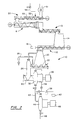
- Figure 1 is a schematic diagram of the wood chip conditioning equipment of the invention combined in an atmospherically decoupled arrangement with RTS rotating disc pulp refiner equipment.
- Figure 2 is a schematic diagram of a second embodiment of the wood chip conditioning equipment of the invention combined in an atmospherically decoupled arrangement with RTS rotating disc pulp refiner equipment.
- Figure 3 is a schematic diagram of a third embodiment of the wood chip conditioning equipment of the invention combined in an atmospherically coupled arrangement with RTS rotating disk pulp refiner equipment.
- Figure 4 depicts a longitudinal sectional view of one embodiment of a compression unit for implementing the invention.
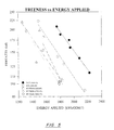
- Figures 5 - 11 are graphs showing various performance aspects of pulp made according to the invention compared to other pulps.
- Figure 12 is an electron photomicrograph (100 x magnification) of a wood chip which has not been conditioned, compressed, or otherwise pretreated.
- Figure 13 is an electron photomicrograph (100 x magnification) of a wood chip which has undergone steam heating and pressurization at 22 psi, and high compression at a 5:1 compression ratio according to the present invention.
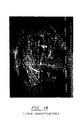
- Figure 14 is an electron photomicrograph (100 x magnification) of a wood chip which has received atmospheric steaming treatment, followed by 4:1 compression.
- FIG. 1 is a schematic diagram of conditioning equipment in an atmospherically decoupled arrangement with an RTS pulp refiner.
- wood chips are introduced to the conditioning equipment via rotary valve 2
- the rotary valve allows chips to be transferred from a storage bin or other bulk feeding means which is open to the atmosphere and is otherwise at ambient conditions of pressure and temperature to the steam tube 3 where conditions of elevated pressure, temperature and optionally moisture are maintained.
- Other means of decoupling the conditioning equipment from the ambient conditions in which the chips are stored or transported may be used.
- the wood chips are resident in the steam tube for a period of time sufficient to condition the chips for subsequent compression. Typically, exposure to conditions of elevated temperature, pressure and optionally moisture for a period of 3 - 180 seconds is sufficient for pulping needs. However, it is envisioned that a 3 - 60 second exposure to pretreatment conditions is preferred.
- the conditions within the steam tube include a temperature in the range of 90 - 150°C and a pressure in the range of 0,69 - 6,89 bar (10 - 100 psi).
- the steam tube has a moist atmosphere. Heating of the steam tube may be accomplished by introducing steam directly to the tube via line 4.
- means may be employed to heat the steam tube and its contents to the operating temperatures of the invention. These means include electric heating coils disposed about the steam tube, or a jacket disposed about the steam tube for heating with steam.
- moisture or water may be introduced to the steam tube along with the wood chips or through an inlet or other conduit means directly into the steam tube itself.
- the conditioned wood chips pass to the inlet end of the screw compression unit 6.
- the screw compression unit features a screw shaft 7 driven by a variable speed motor 8. Disposed along and about the shaft in a generally helical fashion are compression screw flights 9. The screw flights impel the wood chips toward the outlet end of the screw compression device as the shaft is rotated.
- the rotatable screw shaft is outwardly tapered from its narrow, low compression, wood chip inlet end to its wider, high compression, outlet end of the compression unit. Compression of the wood chips in this embodiment is accomplished by the screw flights impelling the wood chips into an ever-decreasing volume space about the shaft.
- the level of compression in the compression unit may be enhanced through the use of a restrictor bolt section 11.
- the restrictor bolt section includes bolts or other projections which extend into the space around the shaft further reducing the volume space in that region and make contact with the wood chips passing through the unit in a manner which "works" the wood chips, destructuring them even further.
- desired compression ratio of from 4:1 - 8:1 of the invention can be attained through various means, including adjusting the volume space about the shaft by altering the taper of the shaft or profile of the housing in which the shaft rotates, changing the pitch of the flights, and adjusting the degree of restriction imposed by the restrictor bolt section. These examples are not intended to limit in any way the means by which the compression aspect of the present invention is accomplished.
- the transfer conveyor and storage bin are both under ambient conditions, although it is within the scope of this invention to maintain the compressed wood chips at elevated pressure and temperature until being further processed.
- water and/or chemicals may be added to the chips by way of water impregnation or chemical impregnation.
- bleaching chemicals may be added by way of chemical impregnation. It is preferred that such water or chemical impregnation be carried out as the wood chips are discharged from the compression device.
- the wood chips are conveyed by plug screw feeder 15 to chamber 20 of, preferably, an RTS refiner system 10.
- the plug screw feeder features a rotatable screw shaft 16 which is rotated by variable speed motor 17. Disposed in a helical fashion about the rotatable screw shaft of the plug screw feeder are screw flights 18. When the screw shaft is rotated, the plug screw flights impel the conditioned wood chips toward the outlet ends of the plug screw feeder.
- the plug screw feeder is designed to cause a degree of crowding of the transported material thereby making a plug of material which effectively atmospherically decouples the downstream outlet end of the plug screw feeder from the inlet end in communication with the storage bin.
- an air cylinder 19 provides pressure relief, thereby preventing the refiner pressure from blowing through the plug.
- the chips are maintained under conditions of elevated temperature, pressure and moisture as required by the RTS preheating process.
- the conditioned chips are conveyed along variable speed screw 22 to the steam separation chamber 24.
- Steam from the separator 24 is routed to chamber 20 for heating and treatment of the wood chips.
- Water or other treatment chemicals may be added to the mixture through line 28.
- the chips experience a saturated steam preheat at a temperature at least 10°C above T g , for a total residence time through vessel 20, screw 22 and separator 24 of between 5 - 10 seconds.
- the preheated wood chips are then driven by a high speed ribbon feeder 30 into the primary refiner 32 which is powered by motor 33.
- the rotating disc operates at a speed greater than 1800 rpm, preferably above 2200 rpm.
- the disks each rotate at a speed greater than 1 500 rpm, preferably above 2,000 rpm.
- Bleaching agents and other chemicals can be introduced into the pulp at primary refiner 32 through lines 34 and 36 by metering system 38 from bleaching agent reservoir 40.
- the primary pulp is fed through line 42 to the secondary refiner 44 which is driven by motor 46.
- the refined pulp of the secondary refiner is transferred by line 48 to a storage facility or other apparatus for further processing into a final product.
- the steam tube can be considered a passive inlet portion of the compression unit 6.
- the pre-treatment process according to the invention may be implemented in hardware in which steam tube or chamber 3 is distinct from compression unit 6, for example as shown in Figures 2 and 3.
- a plug is formed immediately upstream of 11, before expansion at atmospheric pressure at 12. The plug in effect decouples the pre-treatment at elevated temperature and moisture in process, from the atmospheric pressure in storage bin 14.
- the conveyor 13, bin 14 and plug screw feeder 15 can be omitted, and a specially adapted Pressafiner screw device, such as described with respect to Figure 3 below, can be employed to introduce pre-treated material directly into the refiner pre-heating chamber 20.
- the RTS refining system 10 can have a variety of configurations.
- the chamber 20 may be eliminated, because even when present, the level of wood chips therein Is very low, whereby the retention time of the material at the temperatures of T g , can be controlled substantially entirely by controlling the speed of the variable speed conveyor 22.
- FIG 2 a schematic diagram of conditioning equipment in an atmospherically decoupled arrangement with an RTS pulp refiner is shown.
- Wood chips are fed to the apparatus through rotary valve 51.
- the rotary valve is in communication with the inlet end of a variable speed pressurized conveyor 52 which is pressurized and heated by steam line 54.
- the screw flights of rotating screw shaft 53 impel the wood chips from the inlet ends of the pressurized conveyor to the outlet end of the pressurized conveyor.
- the outlet end of the pressurized conveyor is in communication with the wood chip compression unit 6.
- the compression units, transfer conveyor 13, atmospheric bin 14, plug screw feeder 15 and RTS refiner 10 are identical to that previously described in regard to Figure 1.
- An additional embodiment of the apparatus shown in Figure 2 includes the apparatus as described, but with the substitution of the rotary valve 57 by a side-entry plug screw feeder.
- FIG. 3 shows yet another embodiment of the apparatus and method of the invention.
- Wood chips are introduced through rotary valve 70 to the variable speed pressurized conveyor 74.
- a steam line 76 is used to introduce steam to the interior of the pressurized conveyor.
- the steam heats and pressurizes the wood chips being transported through the conveyor and also subjects them to moisture.
- other means be used to subject the wood chips to conditioning levels of heat, pressure and, optionally, moisture. These other means include dry heating of the wood chips through electrically resistive wires disposed around the pressurized conveyor, or indirect heating of the pressurized conveyor through steam jackets or other alternative heating media.
- the pressurized conveyor moves the wood chips from the inlet end to the outlet end thereof and the outlet of the pressurized conveyor is then in communication with a wood chip compression unit 80 featuring a rotatable compression screw shaft 81 driven by a variable speed motor 82.
- the screw shaft features a first flight section 83, a second flight section 85 and a flightless zone 87, a portion of screw shaft without flights, by which the first flight zone and second flight zone are spaced apart.
- the compressive forces imposed upon the wood chips are caused by impelling the wood chips into a decreasing volume space about the shaft and additionally, by forcing the wood chips through a region of the unit where constrictor bolts 90 create additional compression which acts on the wood chips.
- the constrictor bolts are located a distance set back from the outlet end of the compression device.
- the constrictor bolts in this embodiment are disposed in a generally radial pattern around the screw shaft in the interrupted flight zone (flightless zone) of the compression device.
- the constrictor bolts exert additional pressure on the wood chips being impelled through the compression device and also act to "work" the wood chips and aid in destructuring and opening the fibers of the chip.
- the outlet end of the compression unit is in communication with the inlet portions of the RTS refining equipment 10.
- An air cylinder 88 is used at or near the outlet end of the compression unit to prevent the higher atmospheric pressure found in the RTS refiner portion of the apparatus from blowing through the plug of wood chips formed in the compression unit.
- Other features of the RTS refiner portion of this apparatus shown in Figure 3 are as previously described in Figures 1 and 2.
- FIG. 4 depicts a longitudinal sectional view of one embodiment of the wood chip compression unit of the present invention.
- the wood chip compression unit 100 comprises a housing 101 having an inlet end 103 and an outlet end 105.
- the inlet housing (not shown in Fig. 4) is in communication with the conditioning chamber and is preferably configured to permit pressurization of the inlet to process condition pressures.
- Within the housing is a rotatably mounted screw shaft 110 having one or more screw flights 113 disposed about the shaft in a helical arrangement for impelling the wood chips out of the inlet, causing compression of the wood chips, and impelling the wood chips out of the compression unit at the outlet.
- the screw shaft is preferably driven by a variable speed motor 112.
- this embodiment of the compression unit features a screw shaft with a tapered portion 111 for imparting compressive forces to the wood chips.
- the tapered portion of the screw shaft is widest at the end nearest the outlet of the compression unit and narrowed at the inlet portion of the compression unit. This taper to the shaft allows the compression volume space to gradually decrease toward the outlet end of the unit. Wood chips introduced at the inlet are impelled by the screw flights toward the tapered portion of the shaft and the region of decreasing volume space, i.e ., the compression zone of the unit.
- This embodiment of the invention shown in Figure 4 features restrictor bolts 120 near the outlet end of the compression unit.
- the restrictor bolts serve to increase the compressive forces imposed upon the wood chips by further decreasing the flow cross-section about the shaft through which the chips are forced to pass.
- the restrictor bolts are adjustable so that the length of the bolt protruding into the space about the shaft can be adjusted by the operator. This adjustability of the restrictor bolts permits the operator to adjust the compression of the unit as demanded by the process.
- the restrictor bolts also serve to "work" the wood chips which pass through the restrictor bolt region of the unit, further opening, or otherwise destructuring, the fibers of the wood chips.
- a short helical impeller screw flight is located downstream of the restrictor bolts at the outlet of the compression unit.
- the impeller screw 130 serves to move the already compressed wood chips from the unit to the next phase of the pulp process.
- the housing of the unit flares outward at the outlet, thereby increasing the volume space in that area. It is not believed that the impeller screw imposes any additional compression on the wood chips. Rather, the impeller screw merely serves to move the opened wood chips to the next phase of the pulp refining process.
- the inventor performed a number of experiments to evaluate the effect of the wood chip pretreatment process of the invention on RTS and conventional TMP pulp with a view toward determining whether any savings in specific energy requirements accrued when the pretreatment method was employed.
- the inventor discovered that wood chips which were pretreated with the process of the invention and refined at RTS conditions demonstrated a reduction in the specific energy required for refining compared to conventional TMP. This reduction was in the range of 448 - 511 kWh/ODMT, as further shown in Fig. 5.
- wood chips which were not treated according to the process of the invention, but were refined at RTS conditions demonstrated only a 315 kWh/ODMT reduction in specific energy compared to conventional TMP.
- pulps which were refined from wood chips pretreated according to the present invention had the highest strength properties and lowest shive content at a given freeness or specific energy compared to other processes evaluated, as shown in Figures 6 - 11.
- the experiments also revealed that in order to obtain the most benefits from the pretreatment process of the invention, it is most preferable to feed the pretreated wood chips directly to the refiner system without cooling, loss of moisture, or pressure. In this way, further increases in TEA index and reduction in shive content are possible.
- Figure 12 is an electron photomicrograph (100 x magnification) of a wood chip which has not been conditioned, compressed, or otherwise pretreated.
- the micrograph shows the intact rigid fiber structure of the wood and lack of separation of the individual softwood fibers along their longitudinal axis.
- Fig. 13 is an electron photomicrograph (100 x magnification) of a wood chip conditioned and compressed according to the present invention, wherein the chip was exposed to steam heating and pressurization at 22 psi, followed by high compression at a 5:1 compression ratio.
- the micrograph shows a high level of axial separation along the longitudinal axis of the individual softwood fibers. Some surface delamination is also in evidence, which may explain the improved bonding strength results as shown in connection with Figures 6 and 7.
- Fig. 14 is an electron photomicrograph (100 x magnification) of a wood chip which has been atmospherically pre-steamed, then compressed at a 4:1 compression ratio.
- a high level of axial separation of fibers is noted in this micrograph, but this is tempered by the large number of fractured fibers.
- the presence of fibers sheared in the compression step is also noted. Some sheared fibers appear in the lower central region of the micrograph they are identified by the somewhat flattened "O" shape of the sheared end of the fiber.
- Wood samples for these experiments were obtained from Stora SFI of Hawkesbury, Nova Scotia, Canada and blended according to the following distribution:
- Example 1 wood chips were pretreated according to the invention, wherein they were subjected to a saturated steam atmosphere at 22 psi and 128° C for a period of six seconds. The wood chips of Example 1 were then subjected to compression in a PRESSAFINER screw compression device where a compression ratio of 5:1 was achieved. The wood chips were fed to a pressurized single disc refiner (Andritz Model 36-ICP 91 cm (36 inch) diameter) operating at the speed and pressure shown in Table A ( i.e. , RTS operating conditions).
- a pressurized single disc refiner Engelhard Model 36-ICP 91 cm (36 inch) diameter
- Comparative Example 1 a sample of wood chips was exposed to steam under ambient atmospheric conditions for a period of 25 minutes. The steamed chips were then compressed in a PRESSAFINER compression device under conditions suitable to achieve a compression ratio of 4:1.
- Comparative Example 2 the sample of wood chips did not undergo either pretreatment with heat, temperature and pressure or mechanical compression. Rather, the wood chips of Comparative Example 2 were placed directly in the RTS refiner system without receiving pretreatment as in the present invention.
- Example 1 demonstrates improved strength properties including burst index, tear index and tensile index.
- specific energy required for producing the pulp in Example 1 was found to be 172 kWh/ODMT lower than required for the pulp produced in Comparative Example 1.
- Example 1 and Comparative Examples 1 and 2 were similar. However, Example 1 was determined to have a slightly lower percent shive content compared to Comparative Example 1, and a significantly lower percent shive content compared to Comparative Example 2.
- Example 2 The pulp produced in Example 2 showed slightly higher tear index and a lower shive content compared to the pulp produced from the wood chips treated as in Comparative Example 3. This is to be expected from the higher level of thermal softening achieved in the wood chips of Example 2 prior to the primary refining step.
- the results indicate that the RTS system refining conditions of 85 psi and 11 second retention are such that the cooled chips must be heat shocked quite rapidly in order to withstand the high speed (2700 rpm) refining conditions.
- Example 4 Sample ID A5 A10 A18 A23 A12 A14 A18 Process and Refiner Speed (rpm) TMP RTS RTPR (2600) RTPR (2600) RTPR (2600) RTPR (2700) RTPR (2700) Ref. Pressure (PSI) 40 85 85 85 85 75 85 85 Freeness (ml) 115 129 103 104 100 106 103 Tensile (Nm/g) 12.8 14.4 15.1 14.8 14.5 17.2 18.0 % Stretch 0.76 0.72 0.77 0.72 0.81 0.80 0.83 T.E.A.
- the +14 and +28 fraction of the RTS and RTPR pulps were found to have higher tensile and T.E.A. strength properties compared to the conventional TMP long fiber fraction.
Landscapes
- Engineering & Computer Science (AREA)
- Mechanical Engineering (AREA)
- Life Sciences & Earth Sciences (AREA)
- Wood Science & Technology (AREA)
- Chemical & Material Sciences (AREA)
- Chemical Kinetics & Catalysis (AREA)
- General Chemical & Material Sciences (AREA)
- Paper (AREA)
- Polysaccharides And Polysaccharide Derivatives (AREA)
Claims (19)
- Verfahren zur Behandlung von holzzellulosehältigem Eingangsmaterial mit Verfahrensschritten zum Bedampfen des Eingangsmaterials bei erhöhter Temperatur und erhöhtem Druck, Verdichten des bedampften Materials und Einleiten des verdichteten Materials in einen weiteren Prozess zur Abtrennung von Fasern, wobei sich durch die Behandlung des zerstörten Eingangsmaterials ein Faserstoff bildet, wobei die Verbesserung dadurch gekennzeichnet ist, dassdie Bedampfung des Eingangsmaterials in einer Sattdampfumgebung (3, 52, 74) bei einem Druck von mindestens 0,69 bar stattfindet, um aufbereitetes Eingangsmaterial zu erhalten, unddas aufbereitete Eingangsmaterial unmittelbar danach in einer Sattdampfumgebung (6, 80) bei einem Druck von mindestens 0,69 bar verdichtet wird, um die Fasern zu zerstören, ohne dass über die Korngrenzen wesentliche Brüche entstehen.
- Verfahren nach Anspruch 1, dadurch gekennzeichnet, dass die Aufbereitung des Eingangsmaterials unter einem Druck von 0,69 - 6,89 bar erfolgt und die Verdichtung in einer Kompressionsschnecke durchgeführt wird, wobei das Verdichtungsverhältnis im Bereich 4:1 bis 8:1 des nicht verdichteten Volumens des aufbereiteten Eingangsmaterials liegt.
- Verfahren nach Anspruch 1, dadurch gekennzeichnet, dass das zerstörte holzzellulosehältige Material in einem thermomechanischen Verfahren zu Faserstoff aufgeschlossen wird, wobei die folgenden weiteren Schritte:Anwärmen (20, 22) des zerstörten Materials in einer Sattdampfumgebung mit einem über dem Umgebungsdruck (6), bei dem das Material zerstört wurde, liegenden Druck, undFördern (22, 30) des angewärmten Materials in den Einlauf eines Primär-Scheibenrefiners (32), der mit einem über dem Umgebungsdruck (6, 80), bei welchem das Material zerstört wurde, liegenden Druck arbeitet, durchgeführt werden.
- Verfahren nach Anspruch 1, dadurch gekennzeichnet, dassder Aufbereitungsschritt (3, 52, 74) des Eingangsmaterials in einer Sattdampfumgebung bei einer Temperatur von mindestens 120°C und dem entsprechenden Sättigungsdruck erfolgt, um aufbereitetes Eingangsmaterial zu erzeugen,der Verdichtungsschritt (6, 80) für das aufbereitete Eingangsmaterial mit einem Verdichtungsverhältnis von mindestens etwa 4:1 zur Zerstörung der Fasern stattfindet, unddie Weiterverarbeitung zu Faserstoff eine chemische Kochung beinhaltet.
- Verfahren nach Anspruch 1, dadurch gekennzeichnet, dass das zerstörte, holzzellulosehältige Material in einem Verfahren (10) mit kurzer Verweilzeit, hoher Temperatur und hoher Geschwindigkeit zu Faserstoff aufgeschlossen wird, wobei die folgenden weiteren Schritte:durchgeführt werden.Anwärmen (20,22) des zerstörten Materials in einer Sattdampfumgebung bei einer über der Glasübergangstemperatur des Lignins im Material liegenden Druck über eine Dauer von weniger als 30 Sekunden, vorzugsweise 5 bis 10 Sekunden;Fördern (22, 30) des angewärmten Materials in den Einlauf eines Primärscheibenrefiners (32), der mit einer über der Glasübergangstemperatur des Lignins liegenden Temperatur arbeitet, undMahlen des Materials im Refiner bei einer Scheibendrehzahl von über 1500 Upm bei einem Doppelscheibenrefiner oder über 1800 Upm bei einem Einscheibenrefiner,
- Verfahren nach Anspruch 4, dadurch gekennzeichnet, dass das holzzellulosehältige Material in einem Kraftzellstoffverfahren aufgeschlossen wird.
- Verfahren nach einem der Ansprüche 1 - 6, dadurch gekennzeichnet, dass die Aufbereitung (3, 52, 74) des Eingangsmaterials über eine Zeitdauer von ca. 3 - 180 Sekunden abläuft.
- Verfahren nach Anspruch 3 oder 5, dadurch gekennzeichnet, dass vor dem Anwärmen die folgenden Schritte durchgeführt werden:Entleeren (12) des zerstörten Materials auf einen Förderer (13) bei im Wesentlichen Atmosphärendruck;Fördern des abgeleerten Materials in einen Lagersilo (14) bei im Wesentlichen Atmosphärendruck, undFördern des Materials vom Silo mit einer Stopfschnecke (15) über eine Drucksperre (19) in die Umgebung (20, 22) mit höherem Druck, in der das Anwärmen durchgeführt wird.
- Verfahren nach einem der Ansprüche 1 - 8, dadurch gekennzeichnet, dass das Aufbereiten und auch Verdichten in der im Wesentlichen gleichen Sattdampfumgebung stattfinden.
- Verfahren nach Anspruch 3, dadurch gekennzeichnet, dass die Sattdampfumgebung (3, 52, 74, 6, 80) für das Konditionieren und Verdichten einen Sättigungsdruck hat, der einer Temperatur von max. 120°C entspricht und das Anwärmen und Fördern des zerstörten Materials (20, 22, 30) bei einem Sättigungsdruck, der einer Temperatur von über etwa 120°C entspricht, erfolgt.
- Verfahren nach Anspruch 10, dadurch gekennzeichnet, dass die Aufbereitung des Eingangsmaterials über eine Zeitdauer von 3 - 60 Sekunden abläuft.
- Verfahren nach Anspruch 1, 6, oder 7, dadurch gekennzeichnet, dass die Aufbereitung (3, 52, 74) des faserhältigen Eingangsmaterials bei einem Sättigungsdruck von etwa 2,07 - 6,89 bar erfolgt und das aufbereitete Eingangsmaterial unmittelbar danach in einem Verhältnis von mindestens etwa 4:1 in einer Dampfumgebung bei einem Druck von 2,07 - 6,89 bar verdichtet wird (6,80).
- Verfahren nach Anspruch 1, dadurch gekennzeichnet, dass die Aufbreitung (3, 52, 74) in einer Sattdampfumgebung bei einem Druck von etwa 1,03 - 1,72 bar erfolgt, wobeidas aufbereitete Eingangsmaterial danach in einem Verhältnis von mindestens etwa 4:1 in einer Schneckenpresse in einer Sattdampfumgebung bei einem Druck von 1,03 - 1,72 bar verdichtet wird (6, 80), unddas verdichtete Material anschließend einem thermomechanischen Refiner (32) zugeführt wird, um den Faserstoff zu bilden.
- Vorrichtung mit Fördereinrichtung zum Transportieren gelagerter Holzzellulose-Hackschnitzel in eine Dampfbehandlungskammer, einer Zufuhrvorrichtung für die bedampften Hackschnitzel in eine Verdichterschnecke, gefolgt von einer Vorrichtung für die Herstellung von Faserstoff aus den vorher verdichteten Hackschnitzeln, dadurch gekennzeichnet, dassdie Dampfbehandlungskammer (3, 52, 74) und die Verdichtungsschnecke (6,80) miteinander kommunizieren, eine Vorrichtung (4, 54, 76) vorgesehen ist, um Sattdampfbedingungen im Bereich von 0,69 bis 6,89 bar sowohl in der Behandlungskammer als auch in der Verdichtungsschnecke zu schaffen, unddie Schneckenwendel mit dem Gehäuse der Verdichtungsschnecke zur Verdichtung der Hackschnitzel auf ein Verhältnis von 4:1 - 8:1 zusammenarbeiten.
- Vorrichtung nach Anspruch 14, dadurch gekennzeichnet, dass die Vorrichtung zur Herstellung von Faserstoff ein der Verdichtungsschnecke nachgeschalteter Refiner (32) ist.
- Vorrichtung nach Anspruch 14, dadurch gekennzeichnet, dass die Vorrichtung zur Erzeugung von Faserstoff ein der Verdichtungsschnecke nachgelagerter chemischer Kocher ist.
- Vorrichtung nach Anspruch 15, dadurch gekennzeichnet, dass sie mit einerVorrichtung (2, 51, 70) als Drucksperre zwischen dem Eintragsende der Behandlungskammer und den im Wesentlichen atmosphärischen Bedingungen;Vorrichtung (20, 22) nach dem Pfropfen (11, 88) in der Verdichtungsschnecke, um die Hackschnitzel in einer Sattdampfumgebung bei einem über dem Umgebungsdruck in der Verdichtungsschnecke liegenden Druck anzuwärmen, undeinem Scheibenrefiner (32) zur Aufnahme der angewärmten Hackschnitzel ausgerüstet ist.
- Vorrichtung nach Anspruch 17, dadurch gekennzeichnet, dass sie mit einerausgerüstet ist.Vorrichtung (19) zur Errichtung einer Drucksperre zwischen der Anwärmvorrichtung (20, 22) und dem Austrag (12) der Verdichtungsschnecke undeiner unter atmosphärischem Druck arbeitenden Hackschnitzelförder- undSiloanlage (13, 14, 15), die zwischen dem Austrag der Verdichtungsschnecke und der Drucksperre (19) angebracht ist,
- Vorrichtung nach Anspruch 17, dadurch gekennzeichnet, dass der Pfropfen (88) in der Stopfschnecke als Drucksperre zwischen der Sattdampfumgebung in der Stopfschnecke (80) und der Sattdampfumgebung der Anwärmvorrichtung (20, 22) dient und der Austrag aus der Verdichtungsschnecke direkt in die Anwärmvorrichtung geht.
Applications Claiming Priority (3)
| Application Number | Priority Date | Filing Date | Title |
|---|---|---|---|
| US08/907,687 US6899791B2 (en) | 1997-08-08 | 1997-08-08 | Method of pretreating lignocellulose fiber-containing material in a pulp refining process |
| US907687 | 1997-08-08 | ||
| PCT/US1998/014710 WO1999007935A1 (en) | 1997-08-08 | 1998-07-16 | Method of pretreating lignocellulose fiber-containing material for the pulp making process |
Publications (2)
| Publication Number | Publication Date |
|---|---|
| EP1002154A1 EP1002154A1 (de) | 2000-05-24 |
| EP1002154B1 true EP1002154B1 (de) | 2002-09-04 |
Family
ID=25424482
Family Applications (1)
| Application Number | Title | Priority Date | Filing Date |
|---|---|---|---|
| EP98934586A Expired - Lifetime EP1002154B1 (de) | 1997-08-08 | 1998-07-16 | Verfahren zum konditionieren von faserigem lignozellulosematerial für zellstoffherstellung |
Country Status (8)
| Country | Link |
|---|---|
| US (1) | US6899791B2 (de) |
| EP (1) | EP1002154B1 (de) |
| AT (1) | ATE223531T1 (de) |
| AU (1) | AU8407498A (de) |
| CA (1) | CA2297958C (de) |
| DE (1) | DE69807707D1 (de) |
| NO (1) | NO315618B1 (de) |
| WO (1) | WO1999007935A1 (de) |
Cited By (1)
| Publication number | Priority date | Publication date | Assignee | Title |
|---|---|---|---|---|
| RU2413044C1 (ru) * | 2009-12-15 | 2011-02-27 | Общество с ограниченной ответственностью "Научно-технический центр по разработке прогрессивного оборудования" (ООО "НТЦ РПО") | Реактор для непрерывного автогидролиза древесины |
Families Citing this family (30)
| Publication number | Priority date | Publication date | Assignee | Title |
|---|---|---|---|---|
| US6364998B1 (en) * | 1995-06-12 | 2002-04-02 | Andritz Inc. | Method of high pressure high-speed primary and secondary refining using a preheating above the glass transition temperature |
| CA2363158A1 (en) * | 1999-03-02 | 2000-09-08 | Marc J. Sabourin | Feed preconditioning for chemical pulping |
| SE519462C2 (sv) * | 2001-06-21 | 2003-03-04 | Holmen Ab | Förfarande för framställning av blekt termomekanisk massa (TMP) eller blekt kemitermomekanisk massa (CTMP) |
| CN1250811C (zh) * | 2001-07-19 | 2006-04-12 | 安德里兹有限公司 | 四步法碱性过氧化物机械制浆 |
| US20040200586A1 (en) * | 2002-07-19 | 2004-10-14 | Martin Herkel | Four stage alkaline peroxide mechanical pulping |
| JP2003119679A (ja) * | 2001-10-17 | 2003-04-23 | Aikawa Iron Works Co Ltd | パルプ加熱装置 |
| WO2003040462A1 (en) * | 2001-11-09 | 2003-05-15 | Biopulping International, Inc. | Microwave pre-treatment of logs for use in making paper and other wood products |
| SE532703C2 (sv) * | 2002-07-19 | 2010-03-23 | Andritz Inc | Anordning för förbehandling av flis innefattande en skruvpress och en raffinator |
| US7384502B2 (en) * | 2002-12-24 | 2008-06-10 | Nippon Paper Industries Co., Ltd. | Process for impregnating, refining, and bleaching wood chips having low bleachability to prepare mechanical pulps having high brightness |
| AT412787B (de) * | 2003-03-10 | 2005-07-25 | Andritz Ag Maschf | Verfahren und vorrichtung zum austragen von lignozellulosem rohmaterial aus einem kocher und zur förderung des rohmaterials zu einem refiner |
| US8734611B2 (en) | 2008-03-12 | 2014-05-27 | Andritz Inc. | Medium consistency refining method of pulp and system |
| US8814961B2 (en) | 2009-06-09 | 2014-08-26 | Sundrop Fuels, Inc. | Various methods and apparatuses for a radiant-heat driven chemical reactor |
| SE535557C2 (sv) * | 2010-03-05 | 2012-09-25 | Torbjoern Carlberg | Förfarande för framställning av flis |
| US8753476B2 (en) * | 2010-10-06 | 2014-06-17 | Andritz Technology And Asset Management Gmbh | Methods for producing high-freeness pulp |
| US9309627B2 (en) | 2011-07-28 | 2016-04-12 | Georgia-Pacific Consumer Products Lp | High softness, high durability bath tissues with temporary wet strength |
| US9267240B2 (en) | 2011-07-28 | 2016-02-23 | Georgia-Pacific Products LP | High softness, high durability bath tissue incorporating high lignin eucalyptus fiber |
| US8961628B2 (en) | 2012-06-22 | 2015-02-24 | Sundrop Fuels, Inc. | Pretreatment of biomass using steam explosion methods |
| US9126173B2 (en) | 2012-03-26 | 2015-09-08 | Sundrop Fuels, Inc. | Pretreatment of biomass using thermo mechanical methods before gasification |
| US9447326B2 (en) | 2012-06-22 | 2016-09-20 | Sundrop Fuels, Inc. | Pretreatment of biomass using steam explosion methods before gasification |
| US8906198B2 (en) * | 2012-11-02 | 2014-12-09 | Andritz Inc. | Method for production of micro fibrillated cellulose |
| FI127062B (en) * | 2014-11-18 | 2017-10-31 | Upm Kymmene Corp | Method and apparatus for making pulp |
| CA3069318A1 (en) | 2017-07-13 | 2019-01-17 | Poet Research, Inc. | Systems and methods for dewatering a slurry that includes lignocellulosic biomass and liquid |
| CN107559193B (zh) * | 2017-08-23 | 2019-05-03 | 陈则韶 | 一种智能调控双螺杆蒸汽增压设备 |
| US11681280B2 (en) * | 2018-12-31 | 2023-06-20 | Andritz Inc. | Material processing optimization |
| CN109594388B (zh) * | 2019-02-01 | 2024-08-16 | 丰禾新材(北京)技术有限公司 | 一种连续制纸浆设备 |
| JP2023509978A (ja) | 2020-01-09 | 2023-03-10 | ウエストロック・エム・ダブリュー・ヴイ・エルエルシー | 再生紙を含む原料から漂白パルプを製造するための方法 |
| CN113152134B (zh) * | 2021-05-17 | 2023-01-10 | 中国制浆造纸研究院衢州分院 | 一种封闭式撕裂磨浆系统 |
| CN117166273B (zh) * | 2023-09-14 | 2024-01-26 | 中集集装箱(集团)有限公司 | 非汽爆式纯物理制浆方法及制浆生产线 |
| SE548214C2 (en) * | 2024-07-03 | 2026-04-21 | Valmet Ab | Method for isothermal gas impregnation of biomass |
| CN118814283A (zh) * | 2024-07-26 | 2024-10-22 | 莒县海通茧丝绸有限公司 | 一种降低蚕茧蛹吊的方法 |
Family Cites Families (34)
| Publication number | Priority date | Publication date | Assignee | Title |
|---|---|---|---|---|
| US2145851A (en) * | 1934-09-19 | 1939-02-07 | Defibrator Ab | Apparatus for manufacture of pulp |
| US2422522A (en) * | 1940-08-07 | 1947-06-17 | Paper And Ind Appliances Inc | Method for the production of pulp from cellulosic material |
| US2323194A (en) * | 1940-08-07 | 1943-06-29 | Beveridge James Brookes | Apparatus for the production of pulp from cellulosic material |
| US2396587A (en) * | 1941-03-20 | 1946-03-12 | American Defibrator | Apparatus for producing pulp |
| US2972171A (en) * | 1952-10-04 | 1961-02-21 | Weyerhaeuser Co | Production of wood fiber |
| US2904460A (en) * | 1953-07-22 | 1959-09-15 | Control Acting For The Univers | Continuous pulping process |
| US2943012A (en) * | 1955-12-01 | 1960-06-28 | Int Basic Economy Corp | Method and apparatus for fiberizing fibrous material |
| US2935931A (en) * | 1956-12-17 | 1960-05-10 | Bauer Bros Co | Fiberizing press |
| US2975096A (en) * | 1957-11-18 | 1961-03-14 | Bauer Bros Co | Impregnation of wood chips |
| US3098785A (en) * | 1959-03-03 | 1963-07-23 | Bowater Board Company | Method of making lignocellulosic fiberboard |
| CH423451A (de) * | 1963-04-03 | 1966-10-31 | Defibrator Ab | Verfahren zur Herstellung von Faserstoff aus lignozellulosehaltigem Material |
| SE308983B (de) * | 1964-03-10 | 1969-03-03 | Defibrator Ab | |
| US3661328A (en) * | 1970-03-30 | 1972-05-09 | Bauer Bros Co | Pulp refining system and process |
| US3765611A (en) * | 1972-08-07 | 1973-10-16 | Bauer Bros Co | Refining process |
| SE372299B (de) * | 1973-04-27 | 1974-12-16 | Reinhall Rolf | |
| SE413601B (sv) | 1976-06-30 | 1980-06-09 | American Defibrator | Sett vid framstellning av fibermassa i en under angtryck staende malapparat samt anordning for genomforande av settet |
| SE413784B (sv) * | 1976-08-06 | 1980-06-23 | Isel Sa | Sett och anordning for att utnyttja i defibreringszonen utvecklat verme for att minimera angforbrukningen vid framstellning av massa for fiberskivor |
| SE420223B (sv) * | 1979-10-10 | 1981-09-21 | Sunds Defibrator | Forfarande och anordning for framstellning av mekanisk massa |
| FI810330L (fi) | 1980-02-14 | 1981-08-15 | Beloit Corp | Termomekaniskt defibreringsfoerfarande |
| US4372495A (en) * | 1980-04-28 | 1983-02-08 | The Research Foundation Of State University Of New York | Process and apparatus for comminuting using abrasive discs in a disc refiner |
| US4486267A (en) * | 1983-11-14 | 1984-12-04 | Mead Corporation | Chemithermomechanical pulping process employing separate alkali and sulfite treatments |
| US4869783A (en) * | 1986-07-09 | 1989-09-26 | The Mead Corporation | High-yield chemical pulping |
| US5244541A (en) * | 1988-04-28 | 1993-09-14 | Potlatch Corporation | Pulp treatment methods |
| SE461103B (sv) | 1988-05-06 | 1990-01-08 | Svenska Traeforskningsinst | Framstaellning av mekanisk och kemimekanisk massa i tvaa steg |
| SE466060C (sv) | 1990-02-13 | 1995-09-11 | Moelnlycke Ab | Absorberande kemitermomekanisk massa och framställning därav |
| SE468016B (sv) | 1990-06-20 | 1992-10-19 | Sunds Defibrator Ind Ab | Saett foer framstaellning av fiberboard enligt torra metoden innefattande defibrering av lignocellulosahaltigt fibermaterial |
| US5088447A (en) | 1990-07-16 | 1992-02-18 | Alfa-Laval Agri, Inc. | Transponder reader arm assembly |
| AU1368592A (en) | 1991-02-12 | 1992-09-07 | Andritz Sprout-Bauer, Inc. | Adjustable compression screw device and components |
| SE470555B (sv) | 1992-12-30 | 1994-08-22 | Sunds Defibrator Ind Ab | Förfarande för tillverkning av mekanisk och kemimekanisk massa med ett utbyte av över 85 % från lignocellulosahaltigt fibermaterial |
| SE470575B (sv) | 1993-02-01 | 1994-09-19 | Sunds Defibrator Ind Ab | Sätt för framställning av fibermassa av lignocellulosahaltigt fibermaterial där fibermaterialet först inmatas i och passerar kontinuerligt igenom en förvärmare |
| SE9402101L (sv) | 1994-06-15 | 1995-12-16 | Moelnlycke Ab | Lättavvattnad, bulkig, kemimekanisk massa med låg spet- och finmaterialhalt |
| US5622598A (en) * | 1995-04-25 | 1997-04-22 | Ahlstrom Machinery Inc. | Chip pumping to a digester |
| CN1157016A (zh) | 1995-06-12 | 1997-08-13 | 安德里兹·斯普劳特-鲍尔有限公司 | 低停留时间、高温和高速的木屑研磨 |
| WO1998059107A1 (en) | 1997-06-25 | 1998-12-30 | Kvaerner Pulping Ab | Method in connection with the pretreatment of comminuted fibrous material |
-
1997
- 1997-08-08 US US08/907,687 patent/US6899791B2/en not_active Expired - Fee Related
-
1998
- 1998-07-16 AT AT98934586T patent/ATE223531T1/de not_active IP Right Cessation
- 1998-07-16 EP EP98934586A patent/EP1002154B1/de not_active Expired - Lifetime
- 1998-07-16 DE DE69807707T patent/DE69807707D1/de not_active Expired - Lifetime
- 1998-07-16 WO PCT/US1998/014710 patent/WO1999007935A1/en not_active Ceased
- 1998-07-16 CA CA002297958A patent/CA2297958C/en not_active Expired - Fee Related
- 1998-07-16 AU AU84074/98A patent/AU8407498A/en not_active Abandoned
-
2000
- 2000-02-08 NO NO20000638A patent/NO315618B1/no not_active IP Right Cessation
Cited By (1)
| Publication number | Priority date | Publication date | Assignee | Title |
|---|---|---|---|---|
| RU2413044C1 (ru) * | 2009-12-15 | 2011-02-27 | Общество с ограниченной ответственностью "Научно-технический центр по разработке прогрессивного оборудования" (ООО "НТЦ РПО") | Реактор для непрерывного автогидролиза древесины |
Also Published As
| Publication number | Publication date |
|---|---|
| NO20000638D0 (no) | 2000-02-08 |
| AU8407498A (en) | 1999-03-01 |
| US20010050151A1 (en) | 2001-12-13 |
| NO315618B1 (no) | 2003-09-29 |
| WO1999007935A1 (en) | 1999-02-18 |
| ATE223531T1 (de) | 2002-09-15 |
| DE69807707D1 (de) | 2002-10-10 |
| NO20000638L (no) | 2000-02-08 |
| CA2297958C (en) | 2005-09-20 |
| EP1002154A1 (de) | 2000-05-24 |
| CA2297958A1 (en) | 1999-02-18 |
| US6899791B2 (en) | 2005-05-31 |
Similar Documents
| Publication | Publication Date | Title |
|---|---|---|
| EP1002154B1 (de) | Verfahren zum konditionieren von faserigem lignozellulosematerial für zellstoffherstellung | |
| US7758721B2 (en) | Pulping process with high defiberization chip pretreatment | |
| RU2373314C2 (ru) | Установка для изготовления термомеханической древесной массы (варианты), способ термомеханического рафинирования древесной щепы (варианты) и комбинированная плита для диска рафинера | |
| US4270976A (en) | Method of producing peroxide bleached pulp | |
| US6202946B1 (en) | Method and apparatus of defibrating a fibre-containing material | |
| EP2625330B1 (de) | Verfahren zur herstellung von zellstoff mit hohem freenesswert | |
| EP4590893B1 (de) | Verfahren zur herstellung von ht-ctmp mit hoher zugfestigkeit | |
| EP4590894B1 (de) | Herstellung von ctmp aus einer hartholz/weichholz-mischung | |
| EP4590892B1 (de) | Ctmp mit hoher sperrkraft | |
| WO2024133425A1 (en) | Two-step impregnation in production of ctmp from maple wood | |
| WO2024133442A1 (en) | Maple ht-ctmp | |
| WO2024133480A1 (en) | Two-step impregnation in ht-ctmp production | |
| WO2024136742A1 (en) | Ht-ctmp formed from a maple wood/softwood mixture and a method of producing a ht-ctmp from a maple wood/softwood mixture | |
| CN120418057A (zh) | 制备用于生产材料板的颗粒的方法以及材料板 |
Legal Events
| Date | Code | Title | Description |
|---|---|---|---|
| PUAI | Public reference made under article 153(3) epc to a published international application that has entered the european phase |
Free format text: ORIGINAL CODE: 0009012 |
|
| 17P | Request for examination filed |
Effective date: 20000222 |
|
| AK | Designated contracting states |
Kind code of ref document: A1 Designated state(s): AT DE DK ES FI FR GB NL SE |
|
| 17Q | First examination report despatched |
Effective date: 20010108 |
|
| GRAG | Despatch of communication of intention to grant |
Free format text: ORIGINAL CODE: EPIDOS AGRA |
|
| GRAG | Despatch of communication of intention to grant |
Free format text: ORIGINAL CODE: EPIDOS AGRA |
|
| GRAH | Despatch of communication of intention to grant a patent |
Free format text: ORIGINAL CODE: EPIDOS IGRA |
|
| GRAH | Despatch of communication of intention to grant a patent |
Free format text: ORIGINAL CODE: EPIDOS IGRA |
|
| GRAA | (expected) grant |
Free format text: ORIGINAL CODE: 0009210 |
|
| AK | Designated contracting states |
Kind code of ref document: B1 Designated state(s): AT DE DK ES FI FR GB NL SE |
|
| PG25 | Lapsed in a contracting state [announced via postgrant information from national office to epo] |
Ref country code: NL Free format text: LAPSE BECAUSE OF FAILURE TO SUBMIT A TRANSLATION OF THE DESCRIPTION OR TO PAY THE FEE WITHIN THE PRESCRIBED TIME-LIMIT Effective date: 20020904 Ref country code: FR Free format text: LAPSE BECAUSE OF NON-PAYMENT OF DUE FEES Effective date: 20020904 Ref country code: AT Free format text: LAPSE BECAUSE OF FAILURE TO SUBMIT A TRANSLATION OF THE DESCRIPTION OR TO PAY THE FEE WITHIN THE PRESCRIBED TIME-LIMIT Effective date: 20020904 |
|
| REF | Corresponds to: |
Ref document number: 223531 Country of ref document: AT Date of ref document: 20020915 Kind code of ref document: T |
|
| REG | Reference to a national code |
Ref country code: GB Ref legal event code: FG4D |
|
| REF | Corresponds to: |
Ref document number: 69807707 Country of ref document: DE Date of ref document: 20021010 |
|
| PG25 | Lapsed in a contracting state [announced via postgrant information from national office to epo] |
Ref country code: DK Free format text: LAPSE BECAUSE OF FAILURE TO SUBMIT A TRANSLATION OF THE DESCRIPTION OR TO PAY THE FEE WITHIN THE PRESCRIBED TIME-LIMIT Effective date: 20021204 |
|
| PG25 | Lapsed in a contracting state [announced via postgrant information from national office to epo] |
Ref country code: DE Free format text: LAPSE BECAUSE OF FAILURE TO SUBMIT A TRANSLATION OF THE DESCRIPTION OR TO PAY THE FEE WITHIN THE PRESCRIBED TIME-LIMIT Effective date: 20021205 |
|
| NLV1 | Nl: lapsed or annulled due to failure to fulfill the requirements of art. 29p and 29m of the patents act | ||
| PG25 | Lapsed in a contracting state [announced via postgrant information from national office to epo] |
Ref country code: ES Free format text: LAPSE BECAUSE OF FAILURE TO SUBMIT A TRANSLATION OF THE DESCRIPTION OR TO PAY THE FEE WITHIN THE PRESCRIBED TIME-LIMIT Effective date: 20030328 |
|
| EN | Fr: translation not filed | ||
| PLBE | No opposition filed within time limit |
Free format text: ORIGINAL CODE: 0009261 |
|
| STAA | Information on the status of an ep patent application or granted ep patent |
Free format text: STATUS: NO OPPOSITION FILED WITHIN TIME LIMIT |
|
| PG25 | Lapsed in a contracting state [announced via postgrant information from national office to epo] |
Ref country code: GB Free format text: LAPSE BECAUSE OF NON-PAYMENT OF DUE FEES Effective date: 20030716 |
|
| 26N | No opposition filed |
Effective date: 20030605 |
|
| GBPC | Gb: european patent ceased through non-payment of renewal fee |
Effective date: 20030716 |
|
| PGFP | Annual fee paid to national office [announced via postgrant information from national office to epo] |
Ref country code: FI Payment date: 20120710 Year of fee payment: 15 Ref country code: SE Payment date: 20120711 Year of fee payment: 15 |
|
| REG | Reference to a national code |
Ref country code: SE Ref legal event code: EUG |
|
| PG25 | Lapsed in a contracting state [announced via postgrant information from national office to epo] |
Ref country code: SE Free format text: LAPSE BECAUSE OF NON-PAYMENT OF DUE FEES Effective date: 20130717 Ref country code: FI Free format text: LAPSE BECAUSE OF NON-PAYMENT OF DUE FEES Effective date: 20130716 |