EP1002172B1 - Bras d'alimentation en beton presentant des parties articulees - Google Patents
Bras d'alimentation en beton presentant des parties articulees Download PDFInfo
- Publication number
- EP1002172B1 EP1002172B1 EP98941399A EP98941399A EP1002172B1 EP 1002172 B1 EP1002172 B1 EP 1002172B1 EP 98941399 A EP98941399 A EP 98941399A EP 98941399 A EP98941399 A EP 98941399A EP 1002172 B1 EP1002172 B1 EP 1002172B1
- Authority
- EP
- European Patent Office
- Prior art keywords
- arm
- sections
- actuator
- section
- hydraulic motor
- Prior art date
- Legal status (The legal status is an assumption and is not a legal conclusion. Google has not performed a legal analysis and makes no representation as to the accuracy of the status listed.)
- Expired - Lifetime
Links
Images


Classifications
-
- E—FIXED CONSTRUCTIONS
- E04—BUILDING
- E04G—SCAFFOLDING; FORMS; SHUTTERING; BUILDING IMPLEMENTS OR AIDS, OR THEIR USE; HANDLING BUILDING MATERIALS ON THE SITE; REPAIRING, BREAKING-UP OR OTHER WORK ON EXISTING BUILDINGS
- E04G21/00—Preparing, conveying, or working-up building materials or building elements in situ; Other devices or measures for constructional work
- E04G21/02—Conveying or working-up concrete or similar masses able to be heaped or cast
- E04G21/04—Devices for both conveying and distributing
- E04G21/0418—Devices for both conveying and distributing with distribution hose
- E04G21/0436—Devices for both conveying and distributing with distribution hose on a mobile support, e.g. truck
Definitions
- the present invention relates to concrete supply arms mounted on vehicle-transported concrete pumps having several sections and articulating joints between said sections for moving said arm sections along vertical planes.
- the actuator mechanisms must only provide said movement - which occurs along an horizontal plane - without supporting the weight of the single arm sections.
- the actuator mechanisms of the kind of the ones used on the apparatus of UK-A-2132676, may be applied with success in a concrete supply arm, the arm sections of which are foreseen for reciprocal movements along vertical planes ( so that the weight of the single arm sections is at least in part supported by said actuator mechanisms).
- the present application is thus relative to a concrete supply arm - to be mounted on vehicle-transported concrete pumps - having several sections and articulating joints between said sections for moving said arm sections along vertical planes, characterized in that the relative movement of the sections is performed, in correspondence of at least some of the articulating joints of the arm, by means of actuator mechanisms consisting of a worm gear actuated by a hydraulic motor.
- said actuators also comprise a locking brake.
- the relative movement of the sections is performed by means of actuator mechanisms consisting of a worm gear actuated by a hydraulic motor only-at the articulating joints close to the delivery end of the arm.
- the angular velocity at which the relative movement of the sections takes place may be kept constant, without difficulty, over the entire amplitude of the relative angular displacements and the latter may also be much greater than 280°, with obvious advantages for the operators and improvement in the quality of the work.
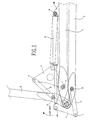
- Fig. 1 shows a schematic view of the construction of an articulation or articulating joint between two end sections of a concrete supply arm according to the prior art: the two sections 1 and 2 are connected by a kinematic mechanism comprising two connecting rods 3 and 4 which are pivotably hinged at 5, 6 and 7 to the two sections 1 and 2 and to one another and a double-acting hydraulic cylinder-piston unit 8, the cylinder of which is pivotably hinged at the closed end at 9 to a lug 1A of the section 1 and the piston of which is pivotably hinged at 10 with its outer end to the connecting rod 3, so as to control the movement of the section 2 with respect to the section 1.
- a kinematic mechanism comprising two connecting rods 3 and 4 which are pivotably hinged at 5, 6 and 7 to the two sections 1 and 2 and to one another and a double-acting hydraulic cylinder-piston unit 8, the cylinder of which is pivotably hinged at the closed end at 9 to a lug 1A of the section 1 and the piston of which is
- the maximum angle by which the section 2 is able to be rotated with respect to the section 1 does not exceed 280° (it is equivalent to about 270°), while the angular velocities at which the sections of the arm may be moved are not constant, but continuously variable, since the angles of relative movement of the sections are not proportional to the stroke of the cylinder.
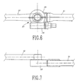
- an internal actuator 13 in line with both the sections 11 and 12 of the arm, is used.
- the actuator comprises a worm gear consisting of a worm screw housed in a casing 14 and of a wheel in engagement with said screw, housed inside a casing 15, the latter being located in a special seat 16 formed at the end of the section 11 of the arm.
- the casing 14 also houses a hydraulic motor which - suitably energised - causes rotation of the the worm screw of the actuator and produces the rotations, in either direction, of the associated wheel, moving the section 12 with respect to the section 11.
- the actuator also comprises preferably parking brake means so as to lock as securely as possible the two sections 11 and 12 in the desired position.
- the actuator 13 is again internal and in line with both the sections, but the rest position of the latter, which in the preceding case consisted in the elements resting on top of each other (section 12 folded underneath the section 11), in this case consists in the elements being aligned with each other, with the section 12 which is at rest being arranged aligned as a continuation of the section 11.
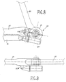
- the actuator 13 is again internal, but is in line with only one of the sections of the arm to be moved relative to one another, for example with the section 11.
- an actuator 23 which is located outside both the sections 21 and 22 of the arm is used.
- the actuator comprises a worm screw housed in a casing 24 and a wheel in engagement with said screw, housed in a casing 25.
- the casing 24 also houses a hydraulic motor which - suitably energised - causes rotation of the worm screw of the actuator and produces rotations, in either direction, of the associated wheel, moving the section 22 with respect to the section 21 .
- the actuator is arranged alongside the ends of the sections 21 and 22 which are articulated with one another and is connected to the section 21 by an anti-torsional bar 21A and to the section 22 by the output shaft moved by the wheel housed inside the casing 25.
- the actuator preferably comprises locking brake means, so as to lock as securely as possible the two sections 21 and 22 in the desired position.
- locking brake means so as to lock as securely as possible the two sections 21 and 22 in the desired position.
- Fig. 10 illustrates a possible construction of an actuator 30 to be applied to any one of the embodiments according to Figs. 2 and 9 of the concrete supply arm according to the invention.
- the actuator illustrated comprises, inside a casing 31 to be associated with the arm by means of the lug 31A, a transmission consisting of a worm screw 32 and of a wheel 33 housed respectively in the parts 34 and 35 of the casing 31, with which there are also associated an orbital hydraulic motor 36, which causes rotation, whenever suitably energised, of the worm screw 32 and a lamellar brake 37 intended to lock in the desired position the shaft of the screw 32 and hence the two sections of the arm on the articulating joint of which the actuator 30 is mounted.
Landscapes
- Engineering & Computer Science (AREA)
- Architecture (AREA)
- Mechanical Engineering (AREA)
- Civil Engineering (AREA)
- Structural Engineering (AREA)
- Manipulator (AREA)
- On-Site Construction Work That Accompanies The Preparation And Application Of Concrete (AREA)
- Reciprocating Pumps (AREA)
- Quick-Acting Or Multi-Walled Pipe Joints (AREA)
- Braking Arrangements (AREA)
- Load-Engaging Elements For Cranes (AREA)
- Jib Cranes (AREA)
Claims (6)
- Bras d'alimentation en béton destiné à être monté sur des pompes à béton transportées sur des véhicules, ayant plusieurs tronçons (11, 12 ; 21, 23) et des joints d'articulation entre lesdits tronçons pour déplacer lesdits tronçons du bras suivant des plans verticaux, caractérisé en ce que le mouvement relatif des tronçons (11, 12 ; 21, 22) du bras est effectué, en correspondance avec au moins certains des joints d'articulation du bras, au moyen d'un mécanisme d'actionneurs (13, 23) consistant en une roue de vis sans fin actionnée par un moteur hydraulique.
- Bras selon la revendication 1, dans lequel lesdits actionneurs comprennent également un frein de blocage.
- Bras selon la revendication 2, dans lequel ledit frein de blocage est un frein feuilleté (37) associé au mécanisme d'actionneurs (31, 32, 33).
- Bras selon la revendication 3, dans lequel ledit moteur hydraulique est un moteur orbital (36).
- Bras selon les revendications 1 à 4, dans lequel le mouvement relatif des tronçons (11, 12 ; 21, 22) est effectué au moyen de mécanismes d'actionneurs consistant en une roue de vis sans fin actionnée par un moteur hydraulique uniquement en correspondance avec les joints d'articulation proches de l'extrémité de distribution du bras.
- Bras selon les revendications 1 à 4, dans lequel le mouvement relatif des tronçons (11, 12 ; 21, 22) est effectué au moyen de mécanismes d'actionneurs consistant en une roue de vis sans fin actionnée par un moteur hydraulique uniquement en correspondance avec le dernier joint d'articulation proche de l'extrémité de distribution du bras.
Applications Claiming Priority (3)
| Application Number | Priority Date | Filing Date | Title |
|---|---|---|---|
| IT97MI001835A IT1293518B1 (it) | 1997-07-31 | 1997-07-31 | Braccio a piu' tronchi snodati per la distribuzione del calcestruzzo |
| ITMI971835 | 1997-07-31 | ||
| PCT/EP1998/004588 WO1999006650A1 (fr) | 1997-07-31 | 1998-07-22 | Bras d'alimentation en beton presentant des parties articulees |
Publications (2)
| Publication Number | Publication Date |
|---|---|
| EP1002172A1 EP1002172A1 (fr) | 2000-05-24 |
| EP1002172B1 true EP1002172B1 (fr) | 2001-10-10 |
Family
ID=11377687
Family Applications (2)
| Application Number | Title | Priority Date | Filing Date |
|---|---|---|---|
| EP98101317A Withdrawn EP0894915A1 (fr) | 1997-07-31 | 1998-01-26 | Bras distributeur de béton avec parties articulées |
| EP98941399A Expired - Lifetime EP1002172B1 (fr) | 1997-07-31 | 1998-07-22 | Bras d'alimentation en beton presentant des parties articulees |
Family Applications Before (1)
| Application Number | Title | Priority Date | Filing Date |
|---|---|---|---|
| EP98101317A Withdrawn EP0894915A1 (fr) | 1997-07-31 | 1998-01-26 | Bras distributeur de béton avec parties articulées |
Country Status (17)
| Country | Link |
|---|---|
| EP (2) | EP0894915A1 (fr) |
| CN (1) | CN1265719A (fr) |
| AR (1) | AR015139A1 (fr) |
| AT (1) | ATE206793T1 (fr) |
| AU (1) | AU8978498A (fr) |
| CA (1) | CA2298508A1 (fr) |
| CO (1) | CO4840534A1 (fr) |
| DE (1) | DE69801997T2 (fr) |
| DK (1) | DK1002172T3 (fr) |
| ES (1) | ES2165698T3 (fr) |
| HR (1) | HRP20000046A2 (fr) |
| IT (1) | IT1293518B1 (fr) |
| PL (1) | PL338450A1 (fr) |
| PT (1) | PT1002172E (fr) |
| TR (1) | TR200000265T2 (fr) |
| WO (1) | WO1999006650A1 (fr) |
| ZA (1) | ZA986638B (fr) |
Cited By (2)
| Publication number | Priority date | Publication date | Assignee | Title |
|---|---|---|---|---|
| DE102019133380A1 (de) * | 2019-11-15 | 2021-05-20 | Schwing Gmbh | Gelenkantrieb mit Schneckengetriebe, Großmanipulator und Autobetonpumpe |
| DE102019133396A1 (de) * | 2019-11-15 | 2021-05-20 | Schwing Gmbh | Gelenkantrieb mit Planetengetriebe, Großmanipulator und Autobetonpumpe |
Families Citing this family (3)
| Publication number | Priority date | Publication date | Assignee | Title |
|---|---|---|---|---|
| AT511833B1 (de) * | 2011-11-10 | 2013-03-15 | Schwing Gmbh F | Mastaufbau insbesondere für eine autobetonpumpe |
| DE102014203054A1 (de) * | 2014-02-20 | 2015-09-03 | Putzmeister Engineering Gmbh | Betonverteilermast, insbesondere einer fahrbaren Betonpumpe |
| CN115613817B (zh) * | 2022-09-08 | 2025-08-05 | 徐州徐工施维英机械有限公司 | 泵车臂架以及泵车 |
Family Cites Families (3)
| Publication number | Priority date | Publication date | Assignee | Title |
|---|---|---|---|---|
| DE1759404C3 (de) * | 1968-04-27 | 1974-03-28 | Friedrich Dipl.-Ing. 4680 Wanne-Eickel Schwing | Vorrichtung zum Verteilen von Beton |
| US3572380A (en) * | 1968-10-08 | 1971-03-23 | Challenge Cook Bros Inc | Concrete pump boom |
| US4519768A (en) * | 1982-10-29 | 1985-05-28 | Takenaka Komuten Co., Ltd. | Apparatus for horizontally casting concrete |
-
1997
- 1997-07-31 IT IT97MI001835A patent/IT1293518B1/it active IP Right Grant
-
1998
- 1998-01-26 EP EP98101317A patent/EP0894915A1/fr not_active Withdrawn
- 1998-07-22 DK DK98941399T patent/DK1002172T3/da active
- 1998-07-22 PT PT98941399T patent/PT1002172E/pt unknown
- 1998-07-22 EP EP98941399A patent/EP1002172B1/fr not_active Expired - Lifetime
- 1998-07-22 ES ES98941399T patent/ES2165698T3/es not_active Expired - Lifetime
- 1998-07-22 HR HR20000046A patent/HRP20000046A2/hr not_active Application Discontinuation
- 1998-07-22 AT AT98941399T patent/ATE206793T1/de active
- 1998-07-22 CA CA002298508A patent/CA2298508A1/fr not_active Abandoned
- 1998-07-22 WO PCT/EP1998/004588 patent/WO1999006650A1/fr not_active Ceased
- 1998-07-22 TR TR2000/00265T patent/TR200000265T2/xx unknown
- 1998-07-22 CN CN98807779A patent/CN1265719A/zh active Pending
- 1998-07-22 PL PL98338450A patent/PL338450A1/xx unknown
- 1998-07-22 AU AU89784/98A patent/AU8978498A/en not_active Abandoned
- 1998-07-22 DE DE69801997T patent/DE69801997T2/de not_active Expired - Lifetime
- 1998-07-24 ZA ZA986638A patent/ZA986638B/xx unknown
- 1998-07-30 CO CO98043557A patent/CO4840534A1/es unknown
- 1998-07-31 AR ARP980103821A patent/AR015139A1/es unknown
Cited By (2)
| Publication number | Priority date | Publication date | Assignee | Title |
|---|---|---|---|---|
| DE102019133380A1 (de) * | 2019-11-15 | 2021-05-20 | Schwing Gmbh | Gelenkantrieb mit Schneckengetriebe, Großmanipulator und Autobetonpumpe |
| DE102019133396A1 (de) * | 2019-11-15 | 2021-05-20 | Schwing Gmbh | Gelenkantrieb mit Planetengetriebe, Großmanipulator und Autobetonpumpe |
Also Published As
| Publication number | Publication date |
|---|---|
| ES2165698T3 (es) | 2002-03-16 |
| TR200000265T2 (tr) | 2000-05-22 |
| CA2298508A1 (fr) | 1999-02-11 |
| AR015139A1 (es) | 2001-04-18 |
| EP1002172A1 (fr) | 2000-05-24 |
| EP0894915A1 (fr) | 1999-02-03 |
| HRP20000046A2 (en) | 2001-10-31 |
| IT1293518B1 (it) | 1999-03-01 |
| DE69801997T2 (de) | 2002-05-16 |
| WO1999006650A1 (fr) | 1999-02-11 |
| ITMI971835A1 (it) | 1999-01-31 |
| DE69801997D1 (de) | 2001-11-15 |
| CO4840534A1 (es) | 1999-09-27 |
| CN1265719A (zh) | 2000-09-06 |
| PL338450A1 (en) | 2000-11-06 |
| DK1002172T3 (da) | 2002-02-11 |
| ZA986638B (en) | 1999-02-02 |
| ATE206793T1 (de) | 2001-10-15 |
| AU8978498A (en) | 1999-02-22 |
| PT1002172E (pt) | 2002-03-28 |
Similar Documents
| Publication | Publication Date | Title |
|---|---|---|
| US7523995B2 (en) | Milling machine | |
| JP2617682B2 (ja) | 連結装置 | |
| US4234150A (en) | Mechanical arm assembly | |
| US4718815A (en) | Device for carrying and adjusting a tool | |
| US5640996A (en) | Large manipulator, especially for self-propelled concrete pumps | |
| JP6106665B2 (ja) | コンクリートポンプのための分配ブーム | |
| NL9101939A (nl) | Hydraulische robot-spuitlans. | |
| US3841436A (en) | Aerial platform with side to side rotatable basket | |
| EP1002172B1 (fr) | Bras d'alimentation en beton presentant des parties articulees | |
| US4799556A (en) | Drilling boom | |
| US4271926A (en) | Rotatable work platform | |
| US5002510A (en) | Steering mechanism for marine propulsion devices | |
| CA1337118C (fr) | Systeme de mise de niveau pour nacelle | |
| DE10058123A1 (de) | Deckenstativeinheit | |
| US4458800A (en) | Folding chute linkage assemblies | |
| US4498568A (en) | Swinging chute linkage assemblies | |
| EP0004837B2 (fr) | Un agencement pour affût de forage | |
| MXPA00001086A (en) | Concrete supply arm with articulated sections | |
| JP3398023B2 (ja) | 鍛造機 | |
| JPS59209790A (ja) | マニピユレ−タ用関節ア−ム | |
| JPH08319093A (ja) | 積込クレーン | |
| CA1115514A (fr) | Support de montage pour lame de boutoir | |
| AU9232998A (en) | Feed shell positioning mechanism | |
| CN217581077U (zh) | 一种地面抹光机的操控系统 | |
| EP0522315A1 (fr) | Dispositif de levage et de positionnement pour une plateforme aérienne de travail, en particulier pour l'utilisation sur des machines-élévatrices |
Legal Events
| Date | Code | Title | Description |
|---|---|---|---|
| PUAI | Public reference made under article 153(3) epc to a published international application that has entered the european phase |
Free format text: ORIGINAL CODE: 0009012 |
|
| 17P | Request for examination filed |
Effective date: 20000219 |
|
| AK | Designated contracting states |
Kind code of ref document: A1 Designated state(s): AT BE CH DE DK ES FI FR GB GR IT LI LU NL PT SE |
|
| GRAG | Despatch of communication of intention to grant |
Free format text: ORIGINAL CODE: EPIDOS AGRA |
|
| 17Q | First examination report despatched |
Effective date: 20010115 |
|
| GRAG | Despatch of communication of intention to grant |
Free format text: ORIGINAL CODE: EPIDOS AGRA |
|
| GRAH | Despatch of communication of intention to grant a patent |
Free format text: ORIGINAL CODE: EPIDOS IGRA |
|
| GRAH | Despatch of communication of intention to grant a patent |
Free format text: ORIGINAL CODE: EPIDOS IGRA |
|
| GRAA | (expected) grant |
Free format text: ORIGINAL CODE: 0009210 |
|
| AK | Designated contracting states |
Kind code of ref document: B1 Designated state(s): AT BE CH DE DK ES FI FR GB GR IT LI LU NL PT SE |
|
| REF | Corresponds to: |
Ref document number: 206793 Country of ref document: AT Date of ref document: 20011015 Kind code of ref document: T |
|
| REG | Reference to a national code |
Ref country code: CH Ref legal event code: EP |
|
| REF | Corresponds to: |
Ref document number: 69801997 Country of ref document: DE Date of ref document: 20011115 |
|
| REG | Reference to a national code |
Ref country code: CH Ref legal event code: NV Representative=s name: E. BLUM & CO. PATENTANWAELTE |
|
| REG | Reference to a national code |
Ref country code: GB Ref legal event code: IF02 |
|
| ET | Fr: translation filed | ||
| REG | Reference to a national code |
Ref country code: DK Ref legal event code: T3 |
|
| REG | Reference to a national code |
Ref country code: ES Ref legal event code: FG2A Ref document number: 2165698 Country of ref document: ES Kind code of ref document: T3 |
|
| REG | Reference to a national code |
Ref country code: PT Ref legal event code: SC4A Free format text: AVAILABILITY OF NATIONAL TRANSLATION Effective date: 20020102 |
|
| REG | Reference to a national code |
Ref country code: GR Ref legal event code: EP Ref document number: 20020400028 Country of ref document: GR |
|
| PLBE | No opposition filed within time limit |
Free format text: ORIGINAL CODE: 0009261 |
|
| STAA | Information on the status of an ep patent application or granted ep patent |
Free format text: STATUS: NO OPPOSITION FILED WITHIN TIME LIMIT |
|
| 26N | No opposition filed | ||
| REG | Reference to a national code |
Ref country code: CH Ref legal event code: PFA Owner name: CIFA S.P.A. Free format text: CIFA S.P.A.#VIALE RIMEMBRANZE, 2#20026 NOVATE MILANESE, MILANO (IT) -TRANSFER TO- CIFA S.P.A.#VIALE RIMEMBRANZE, 2#20026 NOVATE MILANESE, MILANO (IT) |
|
| PGFP | Annual fee paid to national office [announced via postgrant information from national office to epo] |
Ref country code: LU Payment date: 20110725 Year of fee payment: 14 |
|
| PGFP | Annual fee paid to national office [announced via postgrant information from national office to epo] |
Ref country code: GR Payment date: 20130729 Year of fee payment: 16 Ref country code: FI Payment date: 20130711 Year of fee payment: 16 Ref country code: SE Payment date: 20130719 Year of fee payment: 16 Ref country code: PT Payment date: 20130122 Year of fee payment: 16 Ref country code: DK Payment date: 20130719 Year of fee payment: 16 |
|
| PGFP | Annual fee paid to national office [announced via postgrant information from national office to epo] |
Ref country code: GB Payment date: 20130719 Year of fee payment: 16 |
|
| PG25 | Lapsed in a contracting state [announced via postgrant information from national office to epo] |
Ref country code: LU Free format text: LAPSE BECAUSE OF NON-PAYMENT OF DUE FEES Effective date: 20120722 |
|
| PGFP | Annual fee paid to national office [announced via postgrant information from national office to epo] |
Ref country code: NL Payment date: 20140721 Year of fee payment: 17 |
|
| PGFP | Annual fee paid to national office [announced via postgrant information from national office to epo] |
Ref country code: ES Payment date: 20140728 Year of fee payment: 17 Ref country code: FR Payment date: 20140721 Year of fee payment: 17 |
|
| REG | Reference to a national code |
Ref country code: PT Ref legal event code: MM4A Free format text: LAPSE DUE TO NON-PAYMENT OF FEES Effective date: 20150122 |
|
| PGFP | Annual fee paid to national office [announced via postgrant information from national office to epo] |
Ref country code: BE Payment date: 20140722 Year of fee payment: 17 |
|
| REG | Reference to a national code |
Ref country code: DK Ref legal event code: EBP Effective date: 20140731 |
|
| REG | Reference to a national code |
Ref country code: SE Ref legal event code: EUG |
|
| GBPC | Gb: european patent ceased through non-payment of renewal fee |
Effective date: 20140722 |
|
| REG | Reference to a national code |
Ref country code: GR Ref legal event code: ML Ref document number: 20020400028 Country of ref document: GR Effective date: 20150204 |
|
| PG25 | Lapsed in a contracting state [announced via postgrant information from national office to epo] |
Ref country code: PT Free format text: LAPSE BECAUSE OF NON-PAYMENT OF DUE FEES Effective date: 20150122 Ref country code: FI Free format text: LAPSE BECAUSE OF NON-PAYMENT OF DUE FEES Effective date: 20140722 |
|
| PG25 | Lapsed in a contracting state [announced via postgrant information from national office to epo] |
Ref country code: GB Free format text: LAPSE BECAUSE OF NON-PAYMENT OF DUE FEES Effective date: 20140722 Ref country code: GR Free format text: LAPSE BECAUSE OF NON-PAYMENT OF DUE FEES Effective date: 20150204 Ref country code: SE Free format text: LAPSE BECAUSE OF NON-PAYMENT OF DUE FEES Effective date: 20140723 |
|
| PG25 | Lapsed in a contracting state [announced via postgrant information from national office to epo] |
Ref country code: DK Free format text: LAPSE BECAUSE OF NON-PAYMENT OF DUE FEES Effective date: 20140731 |
|
| PGFP | Annual fee paid to national office [announced via postgrant information from national office to epo] |
Ref country code: CH Payment date: 20150721 Year of fee payment: 18 |
|
| REG | Reference to a national code |
Ref country code: NL Ref legal event code: MM Effective date: 20150801 |
|
| REG | Reference to a national code |
Ref country code: FR Ref legal event code: ST Effective date: 20160331 |
|
| PG25 | Lapsed in a contracting state [announced via postgrant information from national office to epo] |
Ref country code: NL Free format text: LAPSE BECAUSE OF NON-PAYMENT OF DUE FEES Effective date: 20150801 Ref country code: FR Free format text: LAPSE BECAUSE OF NON-PAYMENT OF DUE FEES Effective date: 20150731 |
|
| REG | Reference to a national code |
Ref country code: ES Ref legal event code: FD2A Effective date: 20160829 |
|
| PG25 | Lapsed in a contracting state [announced via postgrant information from national office to epo] |
Ref country code: ES Free format text: LAPSE BECAUSE OF NON-PAYMENT OF DUE FEES Effective date: 20150723 |
|
| REG | Reference to a national code |
Ref country code: CH Ref legal event code: PL |
|
| PG25 | Lapsed in a contracting state [announced via postgrant information from national office to epo] |
Ref country code: CH Free format text: LAPSE BECAUSE OF NON-PAYMENT OF DUE FEES Effective date: 20160731 Ref country code: LI Free format text: LAPSE BECAUSE OF NON-PAYMENT OF DUE FEES Effective date: 20160731 |
|
| PG25 | Lapsed in a contracting state [announced via postgrant information from national office to epo] |
Ref country code: BE Free format text: LAPSE BECAUSE OF NON-PAYMENT OF DUE FEES Effective date: 20150731 |
|
| PGFP | Annual fee paid to national office [announced via postgrant information from national office to epo] |
Ref country code: IT Payment date: 20170717 Year of fee payment: 20 Ref country code: DE Payment date: 20170724 Year of fee payment: 20 |
|
| PGFP | Annual fee paid to national office [announced via postgrant information from national office to epo] |
Ref country code: AT Payment date: 20170720 Year of fee payment: 20 |
|
| REG | Reference to a national code |
Ref country code: DE Ref legal event code: R071 Ref document number: 69801997 Country of ref document: DE |
|
| REG | Reference to a national code |
Ref country code: AT Ref legal event code: MK07 Ref document number: 206793 Country of ref document: AT Kind code of ref document: T Effective date: 20180722 |