EP1002177B1 - Procede pour le fonctionnement d'une telecommande, et telecommande associee - Google Patents
Procede pour le fonctionnement d'une telecommande, et telecommande associee Download PDFInfo
- Publication number
- EP1002177B1 EP1002177B1 EP98948731A EP98948731A EP1002177B1 EP 1002177 B1 EP1002177 B1 EP 1002177B1 EP 98948731 A EP98948731 A EP 98948731A EP 98948731 A EP98948731 A EP 98948731A EP 1002177 B1 EP1002177 B1 EP 1002177B1
- Authority
- EP
- European Patent Office
- Prior art keywords
- signal
- remote control
- base station
- signals
- contact
- Prior art date
- Legal status (The legal status is an assumption and is not a legal conclusion. Google has not performed a legal analysis and makes no representation as to the accuracy of the status listed.)
- Expired - Lifetime
Links
- 238000000034 method Methods 0.000 title claims description 17
- 230000004044 response Effects 0.000 claims description 18
- 230000000903 blocking effect Effects 0.000 claims description 4
- 238000002955 isolation Methods 0.000 claims 5
- 230000004913 activation Effects 0.000 claims 1
- 230000015654 memory Effects 0.000 description 14
- 230000005540 biological transmission Effects 0.000 description 6
- 238000004891 communication Methods 0.000 description 5
- 230000008054 signal transmission Effects 0.000 description 5
- 238000012795 verification Methods 0.000 description 5
- 238000000926 separation method Methods 0.000 description 3
- 238000001514 detection method Methods 0.000 description 2
- 238000011156 evaluation Methods 0.000 description 2
- 230000007246 mechanism Effects 0.000 description 2
- 230000009471 action Effects 0.000 description 1
- 230000006399 behavior Effects 0.000 description 1
- 230000008901 benefit Effects 0.000 description 1
- 238000013461 design Methods 0.000 description 1
- 238000010586 diagram Methods 0.000 description 1
- 230000004069 differentiation Effects 0.000 description 1
- 230000006870 function Effects 0.000 description 1
- 238000013507 mapping Methods 0.000 description 1
- 230000008569 process Effects 0.000 description 1
- 230000001960 triggered effect Effects 0.000 description 1
Images

Classifications
-
- G—PHYSICS
- G08—SIGNALLING
- G08C—TRANSMISSION SYSTEMS FOR MEASURED VALUES, CONTROL OR SIMILAR SIGNALS
- G08C19/00—Electric signal transmission systems
- G08C19/16—Electric signal transmission systems in which transmission is by pulses
- G08C19/28—Electric signal transmission systems in which transmission is by pulses using pulse code
Definitions
- the invention is based on a method as in the German patent application DE 197 43 101 A1 is described. Then a remote control is assigned to an in a motor vehicle arranged base station by the latter sends a search signal, whereupon in the range of the Remote controls located by return signals a contact signal to those characteristic of the remote controls Answer times.
- a search signal By evaluating the entry times of the contact signal feedback determines the Base station the remote controls present. One of those selects her to do a challenge / response verification with her perform. Because the information about the remote controls present are not in the contact signal, but contained in the time of its return, the contact signal be simple and the entire detection thereby done very quickly. The detection speed is determined only by the number of provided Time window for the individual remote controls. Should a base station, however, a very large number of remote controls assigned, the procedure loses the Advantage of its speed.
- An electronic identification system is known from US Pat. No. 5,266,925.
- a Interrogation unit is intended to capture information from an electronic label. Are located however, multiple electronic labels in the query area are intended to communicate only with one of the electronic labels. For this the Query unit an address.
- the electronic ones in range Labels receive the address and send a response signal when their specific Identification number is greater than the sent address. Answer several electronic labels simultaneously, the interrogator sends an incremented Address until only an electronic label responds.
- the electronic Labels can send their response signals in time windows that are characteristic of them, which serve as a further distinguishing criterion. It happens within a time window for collisions, the separation procedure described above must be carried out become.
- the problem is solved by a method with the features of the main claim and trained to carry it out Devices according to the subclaims.
- the invention Procedure allowed by individual time slots several remote controls are assigned, the assignment of one large number of remote controls to a base station unchanged high allocation recognition speed. The The number of timeslots can thus be small, the allocation recognition speed be held high.
- several remote controls responding in the same time slot advantageously serves an additional control signal with which the base station causes the remote controls to control Send device codes. Used as recognition information the base station particularly advantageous the intelligibility the returned device codes.
- the remote controls are random to hand over set contact signals excited, the first uniquely responding remote control is selected. Thereby the remote control is also clearly identified then with just a few steps and accordingly quickly if there are several remote controls assigned to the same time slot are within range of the base station.
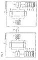
- FIG. 1 shows a block diagram of an assignment arrangement
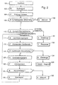
- Figure 2 is a flow chart to illustrate your Operation
- Figure 3 shows the principle of time slot allocation
- Figure 4 the structure of a search signal.
- reference numeral 10 denotes a base station, that can be part of a device or an object or is permanently assigned to one.
- the base station is part of the access control facility Building or a motor vehicle.
- the reference number 20 denotes an actuating device called remote control in the following, which of the base station 10 is functional Assigned contactlessly via a signal transmission path 30 is.
- the remote control 20 can be, for example Be a transponder.
- About active connections, not shown acts the base station 10 on the technical device one whose part or which it is assigned to.
- the core of the base station 10 is a microprocessor 13, which in particular the output of signals by the base station 10 monitors and initiates and incoming signals evaluates. It is connected via a coding / decoding unit 12 a transceiver 11 for delivery or receipt from contactless via the signal transmission path 30 transmitted signals connected.
- the coding / decoding unit 12 is used to encrypt / decrypt the between microprocessor 13 and transceiver 11 exchanged signals.
- the microprocessor 13 is a memory 15 assigned. There is a serial number in it 16, a device code 17, a cryptic key code 31 and a directory 18 with the group numbers and the Device codes assigned to group numbers 27 of the base station 10 assigned remote controls 20.
- the device code 17 denotes the associated device, i.e.
- Serial number 16 is characteristic for mutually assigned base stations 10 and Remote controls 20.
- the ones entered in directory 18 Group numbers 28 differentiate those assigned to a base station 10 Remote controls 20 with the same serial numbers, the respective assigned device code 27 is used in conjunction with the cryptic key code 31 to verify a remote control belonging to the group number 20.
- Equivalent for separate storage of cryptic key codes 31 and device codes 27 can also be entered directly in directory 18 the links used for the verification are stored his. In the directory 18 are also the device codes 27 no longer approved remote controls 20 filed were lost or stolen.
- the serial numbers 16 are determined by the manufacturer of the technical device, the base station 10 or the remote controls 20 assigned. When using the arrangement in motor vehicles For example, the determination by the vehicle manufacturer respectively. The latter can also use the cryptic key code 31 determine by means of which the affiliation of a remote control 20 to the base station 10 is verified.
- the remote control 20 has one on the base station side Transceiver 11 corresponding transceiver 21 to receive from the base stadium 10 emitted signals or to emit contactless transmitted signals to the base station 10.
- the transceiver 21 is a coding / decoding unit 22 encoded for decryption / encryption Downstream signals.
- a microprocessor 24 is connected, which in particular the evaluation of the via the transceiver 21 incoming signals, depending on the results Initiates follow-up action, and the output of output signals supervised.
- One is assigned to the microprocessor 24 Storage unit 25.
- the serial number 16 is one for the base station 10 and associated Actuators 20 existing overall device characteristic code and identical to that in memory 15 the base station 10 contained serial number.
- the group number 28 is used to distinguish the same serial number having remote controls 20. It will be in use the overall device set by the user.
- the device code 27 is made by the manufacturer of the remote control 20 assign and clearly identify them.
- the cryptic Key code 31 is identical to that in the base station 10 existing key code and is used to verify the Belonging to a base station 10. He is by the Manufacturer of the technical associated with the base station 10 Establishment set.
- Signal transmission path 30 for contactless transmission transferable signals between the remote control side Transceiver 21 and the base station side Transceiver 11. From the base station side Transceiver 11 reach outgoing signals all those within their reach at the same time Remote controls 20. Infrared signals are expedient as signals or high frequency signals used.
- a plurality of remote controls 20 can be assigned to a base station 10 his. All assigned remote controls 20 and the Base station 10 itself has 15, 25 in its memories have an identical serial number 16 and use the Verification of an identical cryptic key code 31.
- the individual remote controls 20 differ by their group numbers. They are usually simple assigned so that a remote control by the group number 28 is clearly identified. Certain group numbers can moreover, simultaneously assigned to several remote controls 20 his. Those with the same group number 28 Remote controls 20 differ in their device code 27th
- FIG. 2 The mode of operation is described below with reference to FIGS. 2 and 3 the device shown in Figure 1 explained.
- the process steps in FIG. 2 are each a letter B or F is prefixed, which shows whether the associated process step in the base station 10: B or in the remote control 20: F takes place.
- the mapping recognition process is - usually - through the actuation of a mechanical, electrical, not shown or electro-optical trigger mechanism by a A user resolved, step 100.
- the trigger mechanism for Example of operating the door handle.
- the microprocessor conducts after the released signal has been triggered 13 of the base station 10 the delivery of a search signal through the transceiver 11, step 102.
- the search signal contains essentially one preferably implemented as a start bit Start frequency 35 and the serial number stored in memory 15 16. It is expediently not encrypted.
- the search signal is by everyone within the range of the signal transmission path 30 located remote controls 20 over their Transceivers 21 received.
- Your microprocessors 24 on receipt of a search signal check whether the with the search signal transmitted serial number 16 with the im Memory 25 of the remote control 20 stored as a reference signal serving serial number 16.
- the transferred Start bit 35 is used to synchronize the microprocessor 24 on the received search signal. Does the Microprocessor 24 a match between received Serial number and serial number present in memory 25 fixed, it directs the output of a response in the form of a contact signal on, step 104.
- A serves as the contact signal short, simply structured signal, for example the group number the respective remote control 20 in bit-coded Shape. It is useful like the search signal unencrypted.
- the microprocessor initiates the transmission of the contact signal 24 after the end of a characteristic of the actuating element 20, period determined by the group number the entrance of the search signal. It takes place in a time window with a predetermined length.
- the transmission is dimensioned that a safe assignment of a contact signal to a Time window for both the remote control 20 and for the Base station 10 is possible.
- Figure 3 illustrates the response behavior of the remote controls 20 to a search signal in a graphical representation.
- the abscissa denotes an example in 8 time windows F0, ..., F7 divided time axis t, which corresponds to the input of the Search signals in the remote controls 20 begins.
- the ordinate gives the group number 28 of the respective remote control 20 on.
- a base station 10 has eight group numbers 0 to 7 assigned.
- One remote control each will be present with group numbers 0 or 2 and 3 remote controls with group number 7. They all respond to the search signal by sending out a contact signal according to step 104.
- the time of sending the Contact signals i.e. the serial number of the associated Time window, the group number of the respective remote control.
- the remote control sends with group number 2 your contact signal after the waiting time T2 in the time window F2 off, the remote controls with group number 6 their after the waiting time T6 in the time window F6.
- the Transceiver 11 of the base station 10 go as a result two offset, appearing in windows F2 and F6 Contact signals that immediately indicate which by remote controls identifying their group numbers 20 within the range of the signal transmission path 30 are located.
- the microprocessor 13 By checking whether and in which time windows F0 to F7 contact signals are received, the microprocessor 13 the remote controls 20 present, step 106.
- Present Remote controls 20 are by corresponding entries noted in memory 15. Will not be present remote control 20 determined, an abort signal is issued, step 108, with the the recognition attempt is ended.
- the selected remote control 20 subjects the base station 10 of an assignment correctness check. It is done in the way the well-known Challenge / Response procedure.
- the base station 10 sends a random number generated for this purpose as a challenge to the remote control 20, step 130.
- the microprocessor 13 forms the microprocessor 13 according to a predetermined Algorithm from the device code stored in directory 18 28 of the relevant remote control 20, the cryptographic Key code 31 and the random number a target response signal.
- the challenge signal sent to the remote control 20 is meanwhile by their transmitting / receiving device 21 received and transferred to the microprocessor 24. that directs from the received challenge signal to the same
- Its microprocessor 13 compares Received the returned response signal with the previously determined Target response signal and enters if there is a match Release signal off, a blocking signal if they do not match. A blocking signal is also issued in particular if the device code 27 contained in the response signal is one, after loss or theft, locked remote control 20 listened.
- he remote control 20 is a random number Challenge signal, step 134, it also generates from the random number by linking to the cryptic Key code 31 is a target response signal. The same way meanwhile, the remote control 20 moves with the sent one Challenge signal. The resulting encrypted signal sends them back to bass station 10, step 136.
- the microprocessor 13 compares the received response signal with the previously determined target response signal and outputs a release signal if it matches, if it does not match a lock signal.
- the device can be interpreted by the microprocessor 13 the transmission of a singulation signal, step 120. It is received by the remote controls 20 and sent to their respective Microprocessors 24 forwarded.
- the separation signal causes those to send a contact signal in a randomly chosen, not with the group number 28 linked time slots.
- the microprocessors 24 of the Remote controls 20 cause accordingly after receiving a Separation signals each the random selection of a time window, step 122. For this, link for example the device code 27 present in the memory 25 with one generated by the microprocessor or previously by the Base station 10 sent random number. For that accidentally selected time slot he then prepares the return of the Contact signal.
- the microprocessor 13 of the base station 10 awaits in the meantime the receipt of the first contact signal, step 124. As soon as he noticed the receipt of the first contact signal has, it does not take any further incoming contact signals more on. At the same time, he causes a control signal to be issued, Step 126, which is the sending of further prepared Contact signals through the remote controls 20 in later Time slots lock. Those prevented from broadcasting Remote controls 20 participate in the subsequent communication no longer part. Then the microprocessor 13 again sending an identification signal, Step 114, to those still involved in the communication Remote controls 20. Those in turn respond by sending them back your device code, step 116, which is the base station side Microprocessor 13 in turn on clear interpretability evaluates.
- the microprocessor moves 13 with the implementation of the correctness check continue according to step 130. Results from the examination in step 118 no clear interpretability, repeated the microprocessor 13 as long as steps 114 to 126, until the check in step 128 is a clearly identifiable one Device code results.
- the microprocessor 13 when running through those defined by steps 114 to 126 Loop determines that in response to an identification signal no response contact signal is received, it breaks the association communication ab, step 138, and / or causes others appropriate follow-up.
Landscapes
- Physics & Mathematics (AREA)
- General Physics & Mathematics (AREA)
- Selective Calling Equipment (AREA)
- Lock And Its Accessories (AREA)
Claims (11)
- Procédé pour associer une télécommande (20) à une station de base (10), dans lequel la station de base émet un signal de recherche, la télécommande reçoit le signal de recherche, le compare avec un signal de référence et, en cas de concordance, émet un signal de contact après écoulement d'un espace de temps caractéristique, pour la télécommande (20), qui est déterminée par un numéro de groupe (28) à partir de l'entrée du signal de recherche,
caractérisé par
les autres étapesémission d'un signal d'identification (114) par la station de base (10) après la réception d'un signal de contact (106)réception du signal d'identification par la télécommande (20),envoie en retour par la télécommande (20) d'un code d'appareil (27) qui désigne la télécommande de façon univoque, les télécommandes (20) munies des mêmes numéros de groupe (28) se différenciant par leur code d'appareil (27). - Station de base (10) pour la mise en oeuvre du procédé selon la revendication 1,
caractérisée paretun dispositif démission/réception (11), qui est constituépour l'émission d'un signal de recherche ainsi que d'un signal d'identification,pour la réception de signaux de contact ainsi que de codes d'appareil (27) en provenance d'une télécommande (20), et qui présentent en outre des moyens (13) destinés à provoquer/analyser les signaux qui sont émis/reçu par l'intermédiaire du dispositif démission/réception (11). - Station de base (10) selon la revendication 2, comprenant un dispositif démission/réception (11) configuré de manière que, à l'entrée de signaux de contact appartenant à des télécommandes (20) déterminées, il émet un signal d'identification qui amène toutes les télécommandes (20) qui reçoivent le signal d'identification à envoyer en retour le code d'appareil (17) qui les désigne de façon univoque.
- Station de base (10) selon la revendication 2, comprenant un microprocesseur (13) configuré de façon qu'il contrôle un signal de code d'appareil reçu par une télécommande (20) pour vérifier son aptitude univoque à l'interprétation.
- Station de base (10) selon la revendication 4, comprenant un dispositif démission/réception (11) configuré de façon qu'il soit aussi construit pour émettre un signal d'isolation et qu'il émet un signal d'isolation (120) lorsqu'un code d'appareil ne peut pas être interprété de façon univoque.
- Station de base (10) selon la revendication 5, comprenant un dispositif démission/réception (11) configuré de telle manière qu'à l'entrée du premier signal de contact sur un signal d'isolation, il émet un ordre de blocage (126) qui interdit l'émission de signaux de contact suivant par d'autres télécommandes (20).
- Station de base (10) selon la revendication 2, comprenant un microprocesseur (13) configuré de façon que, pour l'identification d'un élément d'actionnement (20) il analyse des signaux de contact reçu sur l'instant (T2, T6) de leur entrée relativement à l'émission d'un signal de recherche.
- Télécommande (20) pour la mise en oeuvre du procédé selon la revendication 1,
caractérisée parun dispositif démission/réception (21) qui, à la réception de signaux de recherche d'identification, ainsi que pour l'émission de signaux de contact et de code d'appareil, ... le signal de contact étant émis après écoulement d'un espace de temps caractéristique pour la télécommande (20) déterminée par le numéro de groupe (28) à partir de l'entrée du signal de recherche, et un dispositif démission/réception (11) qui présente en outredes moyens (24) pour l'analyse/la commande de signaux reçu/à envoyer. - Télécommande (20) selon la revendication 8,
caractérisée en ce que
lors de la réception d'un signal d'identification, elle émet un signal de code d'appareil (116). - Télécommande (20) selon la revendication 8,
caractérisée en ce qu'
elle est constituée en outre pour la réception de signaux d'isolation et, à la réception d'un signal d'isolation, elle prépare l'envoie d'un signal de contact dans une fenêtre de temps choisie de façon aléatoire (122.). - Dispositif pour associer une télécommande (20) à une station de base ( 10), comprenant une station de base selon la revendication 2 etcaractérisé en ce queplusieurs télécommandes selon la revendication 8 qui peuvent être identifiés par des numéros de groupe (28)le dispositif est configuré de manière qu'un numéro de groupe (28) soit associé simultanément à plusieurs télécommandes (20).
Applications Claiming Priority (3)
| Application Number | Priority Date | Filing Date | Title |
|---|---|---|---|
| DE19734341 | 1997-08-08 | ||
| DE19734341A DE19734341A1 (de) | 1997-08-08 | 1997-08-08 | Verfahren zum Betrieb einer Fernbedienung und Fernbedienung |
| PCT/DE1998/002253 WO1999008471A2 (fr) | 1997-08-08 | 1998-08-05 | Procede pour le fonctionnement d'une telecommande, et telecommande associee |
Publications (2)
| Publication Number | Publication Date |
|---|---|
| EP1002177A2 EP1002177A2 (fr) | 2000-05-24 |
| EP1002177B1 true EP1002177B1 (fr) | 2004-01-07 |
Family
ID=7838362
Family Applications (1)
| Application Number | Title | Priority Date | Filing Date |
|---|---|---|---|
| EP98948731A Expired - Lifetime EP1002177B1 (fr) | 1997-08-08 | 1998-08-05 | Procede pour le fonctionnement d'une telecommande, et telecommande associee |
Country Status (7)
| Country | Link |
|---|---|
| US (1) | US6633227B1 (fr) |
| EP (1) | EP1002177B1 (fr) |
| JP (1) | JP2001513616A (fr) |
| AU (1) | AU732966B2 (fr) |
| DE (2) | DE19734341A1 (fr) |
| ES (1) | ES2214733T3 (fr) |
| WO (1) | WO1999008471A2 (fr) |
Families Citing this family (14)
| Publication number | Priority date | Publication date | Assignee | Title |
|---|---|---|---|---|
| DE19941350A1 (de) * | 1999-03-29 | 2000-10-05 | Mannesmann Vdo Ag | Vorrichtung und Verfahren zur Freigabe einer Sicherheitseinrichtung, insbesondere einer Zuganseinrichtung für ein Kraftfahrzeug |
| EP1041224A3 (fr) | 1999-03-29 | 2004-03-31 | Siemens Aktiengesellschaft | Dispositif et procédé de libération d'un système de sécurité, en particulier d'un système d'accès pour véhicule automobile |
| JP4280949B2 (ja) * | 1999-07-30 | 2009-06-17 | ソニー株式会社 | 情報受信装置、遠隔操作システム、情報受信装置の番組ガイド情報提供方法及び遠隔操作システムの遠隔操作方法 |
| FR2804562B1 (fr) * | 2000-01-27 | 2005-03-18 | Valeo Securite Habitacle | Installation d'acces a distance a des fonctions differentes dans un vehicule automobile |
| WO2002091284A1 (fr) * | 2001-05-04 | 2002-11-14 | Koninklijke Philips Electronics N.V. | Systeme de transpondeur associe a une station de communications comprenant des moyens de generation de signal d'identification de station |
| JP3577482B2 (ja) * | 2002-02-15 | 2004-10-13 | 日産自動車株式会社 | 車載機器通信制御装置 |
| JP3546041B2 (ja) * | 2002-02-15 | 2004-07-21 | 日産自動車株式会社 | 車載機器通信制御装置 |
| EP1537514B1 (fr) * | 2002-08-28 | 2006-03-01 | Koninklijke Philips Electronics N.V. | Procede permettant d'inventorier des transpondeurs au moyen d'une station de communication |
| DE10250676A1 (de) * | 2002-10-31 | 2004-05-13 | Hella Kg Hueck & Co. | Verfahren zur Vermeidung von Kollisionen bei der Anmeldung zumindest einer ersten Vorrichtung an einer zweiten Vorrichtung, Anordnung aus zumindest einer ersten Vorrichtung und einer zweiten Vorrichtung und eine erste Vorrichtung |
| JP4424922B2 (ja) * | 2003-04-02 | 2010-03-03 | 株式会社コナミデジタルエンタテインメント | 遠隔操作玩具、それに用いる無線機及び駆動機器、並びに遠隔操作玩具における識別コード設定方法 |
| US8269612B2 (en) * | 2008-07-10 | 2012-09-18 | Black & Decker Inc. | Communication protocol for remotely controlled laser devices |
| KR101268542B1 (ko) * | 2009-12-21 | 2013-05-28 | 한국전자통신연구원 | 다수의 rfid 태그를 인식하기 위한 시스템 및 방법 |
| US9908182B2 (en) | 2012-01-30 | 2018-03-06 | Black & Decker Inc. | Remote programming of a power tool |
| US20130327552A1 (en) | 2012-06-08 | 2013-12-12 | Black & Decker Inc. | Power tool having multiple operating modes |
Family Cites Families (9)
| Publication number | Priority date | Publication date | Assignee | Title |
|---|---|---|---|---|
| US4471345A (en) * | 1982-03-05 | 1984-09-11 | Sensormatic Electronics Corporation | Randomized tag to portal communication system |
| US5216419A (en) | 1987-12-17 | 1993-06-01 | Omron Tateisi Electronics Co. | Data carrier identification system |
| US5640151A (en) * | 1990-06-15 | 1997-06-17 | Texas Instruments Incorporated | Communication system for communicating with tags |
| US5266925A (en) * | 1991-09-30 | 1993-11-30 | Westinghouse Electric Corp. | Electronic identification tag interrogation method |
| US6172596B1 (en) * | 1994-09-09 | 2001-01-09 | Intermec Ip Corp. | System method and apparatus for identifying and communicating with a plurality of types of radio frequency communication devices |
| FR2724746A1 (fr) * | 1994-09-16 | 1996-03-22 | Int Network For Mobile Electro | Dispositif et procede de tele-controle d'un objet |
| FR2741979B1 (fr) * | 1995-12-01 | 1998-01-23 | Raimbault Pierre | Procede d'interrogation a distance d'etiquettes station et etiquette pour sa mise en oeuvre |
| DE19743101B4 (de) | 1996-11-07 | 2005-10-27 | Robert Bosch Gmbh | Verfahren zum Zuordnen eines Betätigungselementes zu einem Gerät |
| US5822714A (en) * | 1997-03-05 | 1998-10-13 | International Business Machines Corporation | Data processing system and method for accessing a plurality of radio frequency identification tags |
-
1997
- 1997-08-08 DE DE19734341A patent/DE19734341A1/de not_active Withdrawn
-
1998
- 1998-08-05 AU AU95295/98A patent/AU732966B2/en not_active Ceased
- 1998-08-05 US US09/485,378 patent/US6633227B1/en not_active Expired - Lifetime
- 1998-08-05 WO PCT/DE1998/002253 patent/WO1999008471A2/fr not_active Ceased
- 1998-08-05 JP JP2000506791A patent/JP2001513616A/ja active Pending
- 1998-08-05 DE DE59810558T patent/DE59810558D1/de not_active Expired - Lifetime
- 1998-08-05 EP EP98948731A patent/EP1002177B1/fr not_active Expired - Lifetime
- 1998-08-05 ES ES98948731T patent/ES2214733T3/es not_active Expired - Lifetime
Also Published As
| Publication number | Publication date |
|---|---|
| WO1999008471A3 (fr) | 1999-04-29 |
| AU9529598A (en) | 1999-03-01 |
| DE59810558D1 (de) | 2004-02-12 |
| AU732966B2 (en) | 2001-05-03 |
| WO1999008471A2 (fr) | 1999-02-18 |
| US6633227B1 (en) | 2003-10-14 |
| EP1002177A2 (fr) | 2000-05-24 |
| DE19734341A1 (de) | 1999-02-11 |
| ES2214733T3 (es) | 2004-09-16 |
| JP2001513616A (ja) | 2001-09-04 |
Similar Documents
| Publication | Publication Date | Title |
|---|---|---|
| EP1002177B1 (fr) | Procede pour le fonctionnement d'une telecommande, et telecommande associee | |
| DE3851168T2 (de) | Zugangskontrolleinrichtung. | |
| DE3905651C2 (fr) | ||
| EP0523117B1 (fr) | Installation de verrouillage centralise pour vehicules a moteur | |
| DE69926033T2 (de) | Schlüsselkodekorrelationsanordnung | |
| EP1302374A2 (fr) | Procédé d'initialisation d'un système de contrôle d'accès avec plusieurs clées electroniques et plusieurs objéts | |
| EP1035283B1 (fr) | Installation électronique de sécurité avec détermination de zone d'un élément d'authentification, en particulier système de fermeture d'un véhicule | |
| DE10143727B4 (de) | Im Fahrzeug mitgeführtes Schlüsselprüfsystem mit Prüfungshistorienspeicher | |
| EP2340501B1 (fr) | Procédé d'authentification par question/réponse entre un appareil de lecture et un transpondeur sur la base d'une transmission de données sans contact | |
| EP0891606A1 (fr) | Procede et appareil d'affectation d'un dispositif d'authentification a une station de base | |
| DE19652227A1 (de) | Verfahren und Vorrichtung zum Zuordnen einer Fernbedienung zu einer Basisstation | |
| EP0891607B1 (fr) | Procede d'exploitation d'un dispositif de telecommande et telecommande | |
| EP1006248B1 (fr) | Dispositif de contrôle d'accès commandé à distance, en particulier pour un véhicule à moteur et transpondeur portable associé | |
| DE69829819T2 (de) | Transponderkommunikationseinrichtung | |
| DE19743101B4 (de) | Verfahren zum Zuordnen eines Betätigungselementes zu einem Gerät | |
| EP0923054B1 (fr) | Procédé et dispositif pour vérifier le droit d'usage de dispositifs de contrôle d'accès | |
| DE10112573C2 (de) | Verfahren zum Initialisieren eines Diebstahlschutzsystems für ein Kraftfahrzeug | |
| EP0948779B1 (fr) | Dispositif pour attribuer un élément d'opération à un appareil | |
| EP0954666B1 (fr) | Dispositif de commande pour systeme d'autorisation | |
| EP1017916B1 (fr) | Procede d'affectation d'une telecommande a une station de base | |
| DE19841514A1 (de) | Verfahren zum Zuordnen einer Fernbedienung zu einer Basisstation | |
| EP1038080B1 (fr) | Systeme de controle d'autorisation d'acces | |
| DE10056533B4 (de) | Elektronische Fahrzeugschließanlage eines Kraftfahrzeugs | |
| WO2020078855A1 (fr) | Procédé d'ouverture d'un véhicule | |
| DE60105880T2 (de) | Elektronisches Sicherheitssystem für Fahrzeuge |
Legal Events
| Date | Code | Title | Description |
|---|---|---|---|
| PUAI | Public reference made under article 153(3) epc to a published international application that has entered the european phase |
Free format text: ORIGINAL CODE: 0009012 |
|
| 17P | Request for examination filed |
Effective date: 20000308 |
|
| AK | Designated contracting states |
Kind code of ref document: A2 Designated state(s): DE ES FR GB IT |
|
| 17Q | First examination report despatched |
Effective date: 20021025 |
|
| GRAH | Despatch of communication of intention to grant a patent |
Free format text: ORIGINAL CODE: EPIDOS IGRA |
|
| GRAS | Grant fee paid |
Free format text: ORIGINAL CODE: EPIDOSNIGR3 |
|
| GRAA | (expected) grant |
Free format text: ORIGINAL CODE: 0009210 |
|
| AK | Designated contracting states |
Kind code of ref document: B1 Designated state(s): DE ES FR GB IT |
|
| REG | Reference to a national code |
Ref country code: GB Ref legal event code: FG4D Free format text: NOT ENGLISH |
|
| REF | Corresponds to: |
Ref document number: 59810558 Country of ref document: DE Date of ref document: 20040212 Kind code of ref document: P |
|
| GBT | Gb: translation of ep patent filed (gb section 77(6)(a)/1977) |
Effective date: 20040401 |
|
| REG | Reference to a national code |
Ref country code: ES Ref legal event code: FG2A Ref document number: 2214733 Country of ref document: ES Kind code of ref document: T3 |
|
| ET | Fr: translation filed | ||
| PLBE | No opposition filed within time limit |
Free format text: ORIGINAL CODE: 0009261 |
|
| STAA | Information on the status of an ep patent application or granted ep patent |
Free format text: STATUS: NO OPPOSITION FILED WITHIN TIME LIMIT |
|
| 26N | No opposition filed |
Effective date: 20041008 |
|
| PGFP | Annual fee paid to national office [announced via postgrant information from national office to epo] |
Ref country code: ES Payment date: 20060831 Year of fee payment: 9 |
|
| REG | Reference to a national code |
Ref country code: ES Ref legal event code: FD2A Effective date: 20070806 |
|
| PG25 | Lapsed in a contracting state [announced via postgrant information from national office to epo] |
Ref country code: ES Free format text: LAPSE BECAUSE OF NON-PAYMENT OF DUE FEES Effective date: 20070806 |
|
| REG | Reference to a national code |
Ref country code: FR Ref legal event code: PLFP Year of fee payment: 19 |
|
| REG | Reference to a national code |
Ref country code: FR Ref legal event code: PLFP Year of fee payment: 20 |
|
| PGFP | Annual fee paid to national office [announced via postgrant information from national office to epo] |
Ref country code: GB Payment date: 20170824 Year of fee payment: 20 Ref country code: IT Payment date: 20170824 Year of fee payment: 20 Ref country code: FR Payment date: 20170823 Year of fee payment: 20 |
|
| PGFP | Annual fee paid to national office [announced via postgrant information from national office to epo] |
Ref country code: DE Payment date: 20171026 Year of fee payment: 20 |
|
| REG | Reference to a national code |
Ref country code: DE Ref legal event code: R071 Ref document number: 59810558 Country of ref document: DE |
|
| REG | Reference to a national code |
Ref country code: GB Ref legal event code: PE20 Expiry date: 20180804 |
|
| PG25 | Lapsed in a contracting state [announced via postgrant information from national office to epo] |
Ref country code: GB Free format text: LAPSE BECAUSE OF EXPIRATION OF PROTECTION Effective date: 20180804 |