EP1002260B1 - Regler mit zeitdiskreten, dynamischen fuzzy-regelgliedern - Google Patents
Regler mit zeitdiskreten, dynamischen fuzzy-regelgliedern Download PDFInfo
- Publication number
- EP1002260B1 EP1002260B1 EP98945065A EP98945065A EP1002260B1 EP 1002260 B1 EP1002260 B1 EP 1002260B1 EP 98945065 A EP98945065 A EP 98945065A EP 98945065 A EP98945065 A EP 98945065A EP 1002260 B1 EP1002260 B1 EP 1002260B1
- Authority
- EP
- European Patent Office
- Prior art keywords
- fuzzy
- control element
- fax
- fuzzy logic
- variable
- Prior art date
- Legal status (The legal status is an assumption and is not a legal conclusion. Google has not performed a legal analysis and makes no representation as to the accuracy of the status listed.)
- Expired - Lifetime
Links
- 238000012545 processing Methods 0.000 claims description 48
- 230000003068 static effect Effects 0.000 claims description 23
- 238000000034 method Methods 0.000 claims description 11
- 230000008569 process Effects 0.000 claims description 7
- 238000012546 transfer Methods 0.000 claims description 5
- 230000001105 regulatory effect Effects 0.000 claims 1
- 230000005540 biological transmission Effects 0.000 description 38
- 238000010586 diagram Methods 0.000 description 5
- 238000003754 machining Methods 0.000 description 3
- 230000004048 modification Effects 0.000 description 3
- 238000012986 modification Methods 0.000 description 3
- 230000007704 transition Effects 0.000 description 3
- 230000008901 benefit Effects 0.000 description 2
- 238000009749 continuous casting Methods 0.000 description 2
- 230000000694 effects Effects 0.000 description 2
- 238000011156 evaluation Methods 0.000 description 2
- 230000010354 integration Effects 0.000 description 2
- 239000007787 solid Substances 0.000 description 2
- PZASAAIJIFDWSB-CKPDSHCKSA-N 8-[(1S)-1-[8-(trifluoromethyl)-7-[4-(trifluoromethyl)cyclohexyl]oxynaphthalen-2-yl]ethyl]-8-azabicyclo[3.2.1]octane-3-carboxylic acid Chemical compound FC(F)(F)C=1C2=CC([C@@H](N3C4CCC3CC(C4)C(O)=O)C)=CC=C2C=CC=1OC1CCC(C(F)(F)F)CC1 PZASAAIJIFDWSB-CKPDSHCKSA-N 0.000 description 1
- 230000008859 change Effects 0.000 description 1
- 238000013016 damping Methods 0.000 description 1
- 238000001514 detection method Methods 0.000 description 1
- 230000004069 differentiation Effects 0.000 description 1
- 238000005070 sampling Methods 0.000 description 1
- 230000002123 temporal effect Effects 0.000 description 1
- 238000011144 upstream manufacturing Methods 0.000 description 1
Images



Classifications
-
- G—PHYSICS
- G05—CONTROLLING; REGULATING
- G05B—CONTROL OR REGULATING SYSTEMS IN GENERAL; FUNCTIONAL ELEMENTS OF SUCH SYSTEMS; MONITORING OR TESTING ARRANGEMENTS FOR SUCH SYSTEMS OR ELEMENTS
- G05B13/00—Adaptive control systems, i.e. systems automatically adjusting themselves to have a performance which is optimum according to some preassigned criterion
- G05B13/02—Adaptive control systems, i.e. systems automatically adjusting themselves to have a performance which is optimum according to some preassigned criterion electric
- G05B13/0265—Adaptive control systems, i.e. systems automatically adjusting themselves to have a performance which is optimum according to some preassigned criterion electric the criterion being a learning criterion
- G05B13/0275—Adaptive control systems, i.e. systems automatically adjusting themselves to have a performance which is optimum according to some preassigned criterion electric the criterion being a learning criterion using fuzzy logic only
Definitions
- Fuzzy systems used as control elements in conventional controllers are static systems and as such do not have about dynamic transmission properties. You therefore point the properties of non-linear, static transmission elements on.
- linear dynamic control elements To implement dynamic control properties of a fuzzy controller, it is known to use static fuzzy systems with conventional to combine linear dynamic control elements.
- linear dynamic control elements have in particular an integrating, differentiating or proportional transmission characteristic or any combination of these on.
- linear dynamics control elements also as so-called I, D, P, PI, PD or Designated PID control elements.
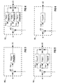
- FIG. 1 and 2 it is known at a controller RE 'linear dynamic control elements with an integrating, differentiating and / or proportional transmission characteristics either before, as shown in Figure 1 or a static fuzzy system control element FU downstream, as shown in Figure 2.
- Figures 1 and 2 are each a linear example Dynamic control element R1 'with proportional, a linear dynamic control element R2 'with integrating and a linear dynamic control element R3 'with differentiating transmission characteristics shown.
- the shown in Figures 1 and 2 known controller RE 'with fuzzy properties through the linear dynamic control elements R1 'to R3' in particular the dynamic properties of a so-called PID controller on.
- Regulators RE ' generally have a reference variable w', in particular for specifying a control setpoint and a feedback variable r 'on.
- Their output variables i.e.
- control elements R1 'to R3' or the fuzzy system control element FU are merged in the controller RE 'and serve as Output variable y 'of controller RE', in particular for regulation a technical process, of which the feedback variable r ' especially as a so-called actual control value back to the controller RE 'is led.
- No. 5,272,621 describes a method and a device known for controlling a process with dead time.
- the procedure includes an evaluation of input signals in the Way that process output responses in relation to known ones Input information can be set.
- the input evaluation criteria are in one or more of the integrator, Proportional and differential process responses are represented.
- a fuzzy PID controller is known from DE 44 20 800 A1 to reduce the time required to determine the manipulated variable Computing time by restricting the membership functions used minimized the rule set to two rules being, the fuzzification, in difference and defuzzification methods are freely selectable.
- the object of the invention is a controller with fuzzy properties to improve so that the control processes, in particular the integration and differentiation processes, easier can be influenced and modified.
- the advantage of the controller according to the invention is that the properties static fuzzy systems and more conventional, linear ones dynamic control elements in the form of discrete-time, dynamic Fuzzy control elements are merged.
- the regulator can therefore only be constructed with control elements, which each systematically dynamic fuzzy properties exhibit.
- inventive Controller fully programmable with standard fuzzy controller software and can be parameterized.
- inventive Controller thus advantageous in software and / or Hardware form feasible.
- the transmission properties the fuzzy control elements can be specifically and clearly modified are.
- fuzzy control elements with an initially in particular approximately linear controller characteristics are advantageously desired controller non-linearities recoverable.
- controller non-linearities recoverable.
- a certain controller characteristic in the simplest way implementable which in particular by in the fuzzy control elements existing linguistic rules, i.e. the fuzzy rules the fuzzy conclusions can be specifically defined, i.e. 'designable' is.
- the time-discrete, dynamic fuzzy control elements are advantageous of the controller according to the invention in particular in the form so-called fuzzy machines. These have internal state variables on, which updates due to fuzzy inferences become.
- the output size is also based on of fuzzy inferences generated in such a way that the fuzzy control element the intended transmission characteristic, in particular at least one integrating and / or differentiating Has transmission characteristics.
- Another advantage is that internal state variables of the Fuzzy control elements of the controller according to the invention in particular formed by a sequence of internal processing states with the fuzzy control element during an update the internal state variable from a previous processing state time-discretely in a following processing state transforms.
- the state variables are advantageous by means of a State graphs can be graphically displayed.
- the controller according to the invention advantageously serves for regulation of a technical process.
- FIG. 3 shows an example of the structure of a device according to the invention Regulator RE with at least one control element FA1 shown.
- the control element FA1 in particular has at least an integrating and / or differentiating transmission characteristic on.
- the control element is FA1 constructed as a discrete-time, dynamic fuzzy control element.
- the controller RE according to the invention is not on only time-discrete, dynamic fuzzy control element limited, but can also do any interconnections of several Have fuzzy control elements.
- the Regulator RE according to the invention also a combination of discrete-time, dynamic fuzzy control elements with conventional, have linear dynamic control elements.
- the inventive one Regulator RE in particular also several time-discrete, dynamic Fuzzy control elements, for example three in parallel arranged discrete-time, dynamic fuzzy control elements FA2, FA3 and FA4.
- the overall transmission characteristic is advantageous to the individual fuzzy control elements FA2 to FA4 divided, each fuzzy control element FA2 to FA4 a specific one Component of the overall transmission characteristic causes.
- FIG. 5 shows a preferred embodiment of the invention Regulator RE shown, which for example due to the three discrete, dynamic, arranged in parallel Fuzzy control elements FA5, FA6 and FA7 an integrating-differentiating-proportional Has transmission characteristics.
- the fuzzy control element FA5 a proportional, integrating the fuzzy control element FA6 and the fuzzy control element FA7 a differentiating one Transmission characteristics.
- Controller RE thus corresponds to a so-called PID controller Fuzzy properties.
- FIG. 6 also shows an example according to the invention Controller RE with a discrete-time, dynamic fuzzy control element FA8 shown, which is an integrating-proportional Has transmission characteristics.
- controller RE shown thus corresponds to a so-called PI controller with fuzzy properties.
- Regulator RE with its exemplary embodiments are, in particular, also referred to as a control setpoint Command variable w and in particular also as a control actual value designated feedback variable r fed.
- the outputs of the respective fuzzy control elements FA1, FA2 to FA4, FA5 to FA7, and FA8 are particularly in the Regulator RE merged to output variable y (i), for example by a direct addition or a weighted addition.
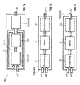
- the inner structure of a time-discrete, dynamic fuzzy control element FAx shown which is a general embodiment of that in FIGS to 6 shown fuzzy control elements FA1, FA2 to FA4, FA5 to FA7 and FA8 describes.
- the fuzzy control element FAx has the input variable with reference to FIGS. 3 to 6 e (i) and the output variable y (i).
- Input and output variable e (i) or y (i) can in particular be vector sizes, i.e.
- Input and output variables e (i) and y (i) can also in the form of several input or output values.
- the fuzzy control element updated the fuzzy control element from the input variable e (i) and out an internal state quantity z (i) based on fuzzy inferences the internal state quantity z (i) such that the Fuzzy control element FAx at least one integrating and / or a differentiating, especially non-linear transfer characteristic having.
- the current state variable z (i) can in particular be a vector size.
- the fuzzy control element FAx of the controller RE preferably at least one first static fuzzy device F (z (i), e (i)). This generates from the input variable e (i) and the current internal state variable z (i) that of the temporal to this following inner state variable z (i + 1). discrete time the fuzzy control element FAx is based on the current internal state variable z (i) into the following inner state variable z (i + 1) about. For example, there is a predetermined by a clock signal Clock rate at which the fuzzy control element FAx the inner State variable z (i) updated.
- the fuzzy control element FAx additionally preferably at least one second static fuzzy device G (z (i), e (i)) to the output variable y (i) of the fuzzy control element Generate FAx based on fuzzy inference. This generates from the input variable e (i) and the current one internal state variable z (i) the current output variable y (i).
- the first and second fuzzy devices F (z (i), e (i)) and G (z (i), e (i)) have the same function, for example the inner one State variable z (i) have the same value as the output variable y (i) is the second fuzzy device G (z (i), e (i)) not required.
- the fuzzy control element shown in FIG. 7a FAx a storage device MZ for temporary storage the current internal state variable z (i).
- the storage device MZ becomes the current internal state variable z (i) saved and time-discrete that of the first static Fuzzy device F (z (i), e (i)) generated the following inner ones State variable z (i + 1) adopted.
- the first static is shown as an example in FIGS. 7b and 7c Fuzzy device F (z (i), e (i)) or the second static fuzzy device G (z (i), e (i)).
- the static fuzzy devices F (z (i), e (i)) and G (z (i), e (i)) become in particular therefore referred to as static because of earlier values not taken into account when generating new values become.
- first and second fuzzy devices F (z (i), e (i)) or G (z (i), e (i)) usually the underlying Fuzzification unit F1 or F2, an inference unit I1 or I2 and a defuzzification unit D1 or D2 based on fuzzy inferences the following inner State variable z (i + 1) or the output variable y (i) is generated.
- FIGS. 8 and 9 show two time-discrete, dynamic ones Fuzzy control elements FAx, for example based on the corresponding State variable z (i) ingestible machining states Zm 'to Zn described.
- This further embodiment The invention is based on state graphs of the time-discrete, dynamic fuzzy control element FAx shown.
- the in The state graph shown in FIG. 8 describes a fuzzy control element FAx with an integrating transmission characteristic and describes the state graph shown in FIG. 9 a fuzzy control element FAx with a differentiating Transfer characteristic.
- the internal state variable z (i) of the fuzzy control element FAx by at least one sequence formed by machining states Zm 'to Z1', Z0, Z1 to Zn, the fuzzy control element FAx during an update the internal state quantity z (i) on the basis of fuzzy inferences time-discrete from a previous processing state changes to a following processing state.
- Each of the processing states Z2 'to Z2 is a specific one Value assigned, for example NM for medium negative Values, NS for small negative values, Z for values which have approximately zero size, PS for small positive ones Values or PM for medium positive values.
- the arrows in the State graphs indicate the change from a current processing state of the fuzzy control element FAx into a following one Processing status.
- the arrows are assigned reference symbols, which are the input variable e (i) and the output variable Specify y (i).
- the significance of the processing states Z2 ' to Z2 serve in particular as fuzzy values for the Input and output variable e (i) and y (i) of the fuzzy control element Fax.
- the arrows shown in the state diagrams for describing the possible transitions between the processing states Z2 'to Z2 and the corresponding output variables y (i) for specific input variables e (i) are used in particular to derive fuzzy conclusions for the fuzzy control element FAx.
- the internal state variable z (i) is determined in particular by the first static fuzzy device F (z (i), e (i)) and the output variable y (i) in particular by the second static fuzzy device G (z (i), e (i)) is updated or generated in accordance with the state diagram, as shown in FIGS. 7b and 7c.
- the exemplary state graphs of FIGS. 8 and 9 show the rules, ie in particular the fuzzy inferences, with which the fuzzy control element FAx, according to an advantageous embodiment, derives the processing state from the input variable e (i) and from the processing state Z2 'to Z2 Z2 'to Z2 updated in such a way and the output variable y (i) generated in such a way that the fuzzy control element FAx has at least one integrating or differentiating transmission characteristic.
- the advantageous embodiments shown here lie with a suitable choice of those on which the fuzzy conclusions are based Membership functions and the underlying inference size initially only a linear or at least approximate linear transmission characteristic of the fuzzy control element FAx based.
- This transmission characteristic forms an advantageous one Starting point for modifications, for example in the form of targeted introduction of non-linearities.
- the state graph of a fuzzy control element shown in FIG. 8 FAx has rules for fuzzy inferences, which an integrating transmission characteristic of the fuzzy control element Effect FAx.
- the output variable y (i) and the updated inner state variable z (i + 1) i.e. the following processing state Z2 'to Z2 den same value NM, NS, Z, PS or PM.
- the fuzzy control element FAx remains in the previous one Processing status Z2 'to Z2.
- the fuzzy control element goes for values PS of the input variable e (i) FAx to the next higher processing state, i.e. for example from PS to PM.
- the input variable e (i) is the fuzzy control element FAx in the next lower processing state above, i.e. for example from PS to Z.
- the fuzzy control element FAx is the input variable e (i) in particular to the next higher processing state, i.e. for example from Z to PM.
- With medium negative values NM of the input variable e (i) is the fuzzy control element FAx in particular in the second next lower processing state about, i.e. for example from Z to NM.
- the state graph of a fuzzy control element shown in FIG. 9 FAx has rules for fuzzy inferences, which a differentiating transmission characteristic of the fuzzy control element Effect FAx.
- the updated, i.e. following processing state Z2 'to Z2 den same value NM to PM as the input variable e (i), so that the input variable is stored.
- the updated internal state variable z (i + 1), i.e. especially the The following processing status is therefore only of depends on the input variable e (i), but not on the current one, i.e. current processing status Z2 'to Z2.
- the fuzzy control element FAx goes into the processing state Z0 above, to which the value Z is assigned.
- the Output variable y (i) results from the current input variable e (i) and the value of the previous input, i.e. the current processing status Z2 'to Z2.
- the the value NS is assigned an input variable e (i) with the Value Z the following processing state Z0, which the value Z is assigned and an output variable y (i) with a small positive Value PS.
- the output variable y (i) such as PB and NB for large positive or negative values and PH and NH for very large positive or negative values.
- FIGs 10 and 11 are with reference to those in the Figures 8 and 9 embodiments of the invention with integrating or differentiating transmission characteristics each a diagram showing the input and Output variable e (i) or y (i) of the corresponding time-discrete, dynamic fuzzy control element FAx shown as an example.
- the respective fuzzy control element FAx first an almost linear transmission characteristic. These almost linear transmission characteristics are through Subsequent introduction of non-linearities can be specifically changed, to achieve a desired control behavior.
- the thin solid curves in Figures 10 and 11 represents the corresponding input variable e (i), which here, for example have a sinusoidal shape.
- the bold, solid curves represent the corresponding Output variable y (i), which is the integral or derivative function of the corresponding input variable e (i).
- the output variable y (i) has a step-like shape Course on.
- the size of the steps is particularly due to the Sampling rate variable, i.e. the clock rate with which the discrete-time, dynamic fuzzy control element FAx the internal state variable z (i) updated.
- FIGS. 12a, 12b and 13 show an example of like a regulator RE according to the invention through the targeted introduction can advantageously be modified by non-linearities.
- Changing the rules, i.e. of fuzzy inferences, can especially by changing the arrows and the associated ones Output variable y (i) in the state graph.
- the representations of Figures 12a, 12b and 13 are for clarity incomplete, i.e. it is particular not all transitions between the processing states Z2 'to Z2 shown and serve only for illustration of modification principles, which apply in particular to the Embodiments of Figures 8 and 9 are transferable.
- the exemplary embodiments shown in FIGS. 12a and 12b concern the state graphs of two time discrete dynamic fuzzy control elements FAx with integrating transmission characteristics, which as so-called 'anti-wind-up' control elements are modified.
- the fuzzy control elements FAx are finite, i.e. limited number of processing states, here, for example, the five processing states Z2 'to Z2 limits, causing the external machining states Z2 'and Z2 must not be exceeded or fallen short of can.
- the fuzzy control element FAx remains in the example 12a in the highest processing state PB, too if a large positive value PB is entered as the input variable which would otherwise cause a jump over three states. in the The example of FIG.
- the embodiment shown in Figure 13 relates the state graph of a discrete-time, dynamic fuzzy control element Fax. with modified, differentiating transmission characteristics.
- Small positive and negative values PS or NS of the input variable cause a transition of the fuzzy control element Fax from the processing state Z in the corresponding subsequent processing state, for example from Z to PS, from Z to NS or vice versa, the output size is, however, for small values in particular to the value Z, i.e. reduced to zero. This is particularly the damping caused by noise and interference signals of the input variable.
Landscapes
- Engineering & Computer Science (AREA)
- Artificial Intelligence (AREA)
- Software Systems (AREA)
- Physics & Mathematics (AREA)
- Health & Medical Sciences (AREA)
- Mathematical Physics (AREA)
- Fuzzy Systems (AREA)
- Computer Vision & Pattern Recognition (AREA)
- Evolutionary Computation (AREA)
- Medical Informatics (AREA)
- General Physics & Mathematics (AREA)
- Automation & Control Theory (AREA)
- Feedback Control In General (AREA)
Description
- FIG 1
- einen bekannten Regler mit Fuzzy-Eigenschaften, welcher ein herkömmliches statisches Fuzzy-System aufweist, welchem drei lineare Dynamik-Regelglieder mit einer integrierenden, differenzierenden bzw. proportionalen Übertragungscharakteristik vorgeschaltet sind,
- FIG 2
- eine Ausführungsform des bekannten und bereits in der Figur 1 dargestellten Reglers mit dem herkömmlichen statischen Fuzzy-System nachgeschalteten linearen Dynamik-Regelgliedern,
- FIG 3
- einen erfindungsgemäßen Regler mit einem zeitdiskreten, dynamischen Fuzzy-Regelglied,
- FIG 4
- einen erfindungsgemäßen Regler mit drei parallel geschalteten zeitdiskreten, dynamischen Fuzzy-Regelgliedern,
- FIG 5
- eine bevorzugte Ausführungsform des erfindungsgemäßen Reglers gemäß der Figur 4, wobei ein sogenannter PID-Regler gebildet wird, welcher eine integrierenddifferenzierend-proportionale Übertragungscharakteristik aufweist,
- FIG 6
- eine Ausführungsform des erfindungsgemäßen Reglers gemäß der Figur 5, wobei die Fuzzy-Regelglieder mit integrierender und differenzierender Übertragungscharakteristik in einem Fuzzy-Regelglied zusammengefaßt sind,
- FIG 7a
- die innere Struktur einer allgemeinen Ausführungsform eines zeitdiskreten, dynamischen Fuzzy-Regelglieds, welches eine erste und zweite statische Fuzzyeinrichtung und eine Speichereinrichtung für die innere Zustandsgröße aufweist,
- FIG 7b
- die innere Struktur einer bevorzugten Ausführungsform der ersten statischen Fuzzyeinrichtung eines zeitdiskreten, dynamischen Fuzzy-Regelglieds,
- FIG 7c
- die innere Struktur einer bevorzugten Ausführungsform der zweiten statischen Fuzzyeinrichtung eines zeitdiskreten, dynamischen Fuzzy-Regelglieds,
- FIG 8
- einen Zustandsgraphen eines zeitdiskreten, dynamischen Fuzzy-Regelglieds mit integrierender Übertragungscharakteristik,
- FIG 9
- einen Zustandsgraphen eines zeitdiskreten, dynamischen Fuzzy-Regelglieds mit differenzierender Übertragungscharakteristik,
- FIG 10
- ein beispielhaftes Diagramm zur Darstellung der Eingangs- und Ausgangsgröße des in der Figur 8 dargestellten zeitdiskreten, dynamischen Fuzzy-Regelglieds mit integrierender Übertragungscharakteristik für den Spezialfall einer linear ausgelegten Übertragungscharakteristik,
- FIG 11
- ein beispielhaftes Diagramm zur Darstellung der Eingangs- und Ausgangsgröße des in der Figur 9 dargestellten zeitdiskreten, dynamischen Fuzzy-Regelglieds mit differenzierender Übertragungscharakteristik für den Spezialfall einer linear ausgelegten Übertragungscharakteristik,,
- FIG 12a
- einen Zustandsgraphen eines ersten zeitdiskreten, dynamischen Fuzzy-Regelglieds mit integrierender Übertragungscharakteristik, welches durch gezieltes Einbringen von Nichtlinearitäten als sogenanntes 'AntiWind-Up'-Regelglied modifiziert ist,
- FIG 12b
- einen Zustandsgraphen eines ersten, als sogenanntes 'Anti-Wind-Up'-Regelglied modifizierten Fuzzy-Regelglieds, und
- FIG 13
- einen Zustandsgraphen eines zeitdiskreten, dynamischen Fuzzy-Regelglieds mit differenzierender Übertragungscharakteristik, wobei im Bearbeitungszustand Z kleine Eingabegrößen nicht auf die Ausgangsgröße wirken.
In den beispielhaften Zustandsgraphen der Figuren 8 und 9 sind die Regeln, d.h. insbesondere die Fuzzy-Folgerungen, wiedergegeben, mit denen das Fuzzy-Regelglied FAx gemäß einer vorteilhaften Ausführungsform aus der Eingangsgröße e(i) und aus dem Bearbeitungszustand Z2' bis Z2 den Bearbeitungszustand Z2' bis Z2 derartig aktualisiert und die Ausgangsgröße y(i) derartig erzeugt, daß das Fuzzy-Regelglied FAx zumindest eine integrierende bzw. eine differenzierende Übertragungscharakteristik aufweist.
Claims (6)
- Regler (RE) mit wenigstens einem Regelglied (FA1..FA8), insbesondere mit zumindest einer integrierenden (FA6, FA8) und/oder differenzierenden (FA7) Übertragungscharakteristik,
dadurch gekennzeichnet, daß das Regelglied (FA1..FA8) als ein zeitdiskretes, dynamisches Fuzzy-Regelglied (FAx) aufgebaut ist, das eine Speichereinrichtung (MZ) zur Zwischenspeicherung einer aktuellen inneren Zustandsgröße (z(i)) auf der Grundlage von Fuzzy-Folgerungen (F1, I1, D1, F2, I2, D2) aufweist. - Regler (RE) nach Anspruch 1,
dadurch gekennzeichnet, daß das Fuzzy-Regelglied (FAx, FA1..FA8) aus einer Eingangsgröße (e(i)) und aus einer inneren Zustandsgröße (z(i)) auf der Grundlage von Fuzzy-Folgerungen (F1, I1, D1 F2, I2, D2) die innere Zustandsgröße (z(i)) derartig aktualisiert (z(i+1), F(z(i), e(i))) und eine Ausgangsgröße (y(i)) derartig erzeugt (G(Z(i), e(i))), daß das Fuzzy-Regelglied (FAx) zumindest eine integrierende und/ oder eine differenzierende, insbesondere nichtlineare Übertragungscharakteristik (e(i), y(i)) aufweist (FIG 7a). - Regler (RE) nach einem der Ansprüche 1 oder 2,
dadurch gekennzeichnet, daß das Fuzzy-Regelglied (FAx) wenigstens eine erste statische Fuzzyeinrichtung (F(z(i),e(i))) zur Aktualisierung der inneren Zustandsgröße (z(i)) des Fuzzy-Regelglieds (FAx) auf der Grundlage von Fuzzy-Folgerungen aufweist (FIG 7b). - Regler (RE) nach einem der Ansprüche 1 bis 3,
dadurch gekennzeichnet, daß das Fuzzy-Regelglied (FAx) wenigstens eine zweite statische Fuzzyeinrichtung (G(z(i),e(i))) zur Erzeugung der Ausgangsgröße (y(i)) des Fuzzy-Regelglieds (FAx) auf der Grundlage von Fuzzy-Folgerungen aufweist (FIG 7c). - Regler (RE) nach einem der Ansprüche 1 bis 4,
dadurch gekennzeichnet, daßa) die innere Zustandsgröße (z(i)) des Fuzzy-Regelglieds (FAx) durch wenigstens eine Folge von Bearbeitungszuständen (Zm'..Z1', Z0, Z1..Zn) gebildet wird, undb) das Fuzzy-Regelglied (FAx) bei einer Aktualisierung der inneren Zustandsgröße (z(i)) von einem bisherigen Bearbeitungszustand (Zm'..Zn) zeitdiskret in einen folgenden Bearbeitungszustand (Zm'..Zn) übergeht (FIG 8, FIG 9). - Verwendung eines Reglers (RE) nach einem der vorangegangenen Ansprüche zur Regelung eines technischen Prozesses.
Applications Claiming Priority (3)
| Application Number | Priority Date | Filing Date | Title |
|---|---|---|---|
| DE19734711 | 1997-08-11 | ||
| DE19734711A DE19734711C1 (de) | 1997-08-11 | 1997-08-11 | Regler mit zeitdiskreten, dynamischen Fuzzy-Regelgliedern |
| PCT/DE1998/002163 WO1999008163A2 (de) | 1997-08-11 | 1998-07-29 | Regler mit zeitdiskreten, dynamischen fuzzy-regelgliedern |
Publications (2)
| Publication Number | Publication Date |
|---|---|
| EP1002260A2 EP1002260A2 (de) | 2000-05-24 |
| EP1002260B1 true EP1002260B1 (de) | 2002-10-09 |
Family
ID=7838612
Family Applications (1)
| Application Number | Title | Priority Date | Filing Date |
|---|---|---|---|
| EP98945065A Expired - Lifetime EP1002260B1 (de) | 1997-08-11 | 1998-07-29 | Regler mit zeitdiskreten, dynamischen fuzzy-regelgliedern |
Country Status (4)
| Country | Link |
|---|---|
| US (1) | US7054846B1 (de) |
| EP (1) | EP1002260B1 (de) |
| DE (2) | DE19734711C1 (de) |
| WO (1) | WO1999008163A2 (de) |
Families Citing this family (5)
| Publication number | Priority date | Publication date | Assignee | Title |
|---|---|---|---|---|
| DE19919206A1 (de) | 1999-04-28 | 2000-11-02 | Buehler Ag | Verfahren zur Herstellung von Teigwaren |
| DE19931181B4 (de) * | 1999-07-07 | 2004-12-09 | Bühler AG | Verfahren und Vorrichtung zur Optimierung der Prozessführung sowie Prozessüberwachung in einer Anlage zur Schokoladeherstellung |
| DE102004052418B4 (de) * | 2004-10-28 | 2012-05-10 | Infineon Technologies Ag | Gewichtungsschaltung und Verfahren zum Einregeln eines Regelkreises |
| DE102008043848A1 (de) * | 2008-11-19 | 2010-05-20 | Zf Friedrichshafen Ag | Elektronische Regleranordnung zur Regelung der Drehzahl einer Brennkraftmaschine |
| US7917954B1 (en) | 2010-09-28 | 2011-03-29 | Kaspersky Lab Zao | Systems and methods for policy-based program configuration |
Family Cites Families (12)
| Publication number | Priority date | Publication date | Assignee | Title |
|---|---|---|---|---|
| DE3811086A1 (de) * | 1987-04-03 | 1988-10-20 | Hitachi Ltd | Pid-reglersystem |
| JP2553675B2 (ja) * | 1988-11-18 | 1996-11-13 | 日本電気硝子株式会社 | プロセスの制御方法 |
| EP0474492B1 (de) * | 1990-09-07 | 1995-11-15 | Kabushiki Kaisha Toshiba | Regelungssystem des Typs mit zwei Freiheitsgraden |
| JPH04119814A (ja) * | 1990-09-10 | 1992-04-21 | Nissei Plastics Ind Co | 射出成形機の温度制御方法 |
| US5471381A (en) * | 1990-09-20 | 1995-11-28 | National Semiconductor Corporation | Intelligent servomechanism controller |
| JPH064266B2 (ja) * | 1990-10-18 | 1994-01-19 | 日精樹脂工業株式会社 | 射出成形機の非干渉温度制御方法 |
| US5272428A (en) * | 1992-02-24 | 1993-12-21 | The United States Of America As Represented By The U.S. Environmental Protection Agency | Fuzzy logic integrated control method and apparatus to improve motor efficiency |
| JPH05313705A (ja) * | 1992-05-12 | 1993-11-26 | Hitachi Ltd | プロセス制御方法および装置 |
| KR970005988B1 (ko) * | 1992-11-16 | 1997-04-22 | 대우전자 주식회사 | 디스크드라이브의 헤드위치제어시스템 |
| DE4302574A1 (de) * | 1993-01-29 | 1994-08-04 | Siemens Ag | Regler zur Regelung in einem geschlossenen Regelkreis |
| DE4420800A1 (de) * | 1994-06-16 | 1995-12-21 | Fred Dr Ros | Fuzzy-PID-Regler |
| DE59600581D1 (de) | 1995-04-03 | 1998-10-22 | Siemens Ag | Einrichtung zur durchbruch-früherkennung beim stranggiessen |
-
1997
- 1997-08-11 DE DE19734711A patent/DE19734711C1/de not_active Expired - Fee Related
-
1998
- 1998-07-29 DE DE59805914T patent/DE59805914D1/de not_active Expired - Lifetime
- 1998-07-29 US US09/485,445 patent/US7054846B1/en not_active Expired - Fee Related
- 1998-07-29 EP EP98945065A patent/EP1002260B1/de not_active Expired - Lifetime
- 1998-07-29 WO PCT/DE1998/002163 patent/WO1999008163A2/de not_active Ceased
Also Published As
| Publication number | Publication date |
|---|---|
| US7054846B1 (en) | 2006-05-30 |
| EP1002260A2 (de) | 2000-05-24 |
| WO1999008163A3 (de) | 1999-06-10 |
| DE19734711C1 (de) | 1999-04-15 |
| WO1999008163A2 (de) | 1999-02-18 |
| DE59805914D1 (de) | 2002-11-14 |
Similar Documents
| Publication | Publication Date | Title |
|---|---|---|
| DE69823049T2 (de) | Modellfreie adaptive prozesssteuerung | |
| DE102004019352B4 (de) | Zustandsbasierter adaptiver Feedback-/Feedforward-PID-Regler (PID-Steuerungseinheit) | |
| DE69420734T2 (de) | Mehrbereichs-fuzzy-logik regelungssystem mit hilfsvariablen | |
| DE10341574A1 (de) | Konfiguration und Betrachtungsanzeige für einen integrierten prädiktiven Modellsteuerungs- und Optimierungsfunktionsblock | |
| DE10341573A1 (de) | Integrierte modellbasierte prädikative Steuerung und Optimierung innerhalb eines Prozesssteuerungssystems | |
| DE4240984B4 (de) | Steuerschaltung und Netzteil für Fernsehgeräte | |
| DE19910311A1 (de) | Automatisierungssystem mit wiederverwendbaren Automatisierungsobjekten und Verfahren zur Wiederverwendung von Automatisierungslösungen in Engineering-Werkzeugen | |
| DE3343854C2 (de) | ||
| DE69119562T2 (de) | Steuerungssystem mit gleitender Wirkungsweise | |
| EP1119799B1 (de) | Regeleinrichtung zur regelung einer strecke mit mehreren verkoppelten regelgrössen | |
| EP0706680B1 (de) | Regeleinrichtung, insbesondere für einen nichtlinearen, zeitvarianten prozess | |
| EP1122517B1 (de) | Navigationssystem und Verfahren zur nutzerspezifischen Anpassung eines Navigationssystems | |
| EP0998700A2 (de) | Verfahren zur generierung von ankopplungsbahnen, verwendbar zur führung eines fahrzeugs zu einer vorgegebenen zielbahn | |
| DE4204047C2 (de) | Verfahren und Vorrichtung zur Positionierung eines Stellers in einem Kraftfahrzeug | |
| EP1002260B1 (de) | Regler mit zeitdiskreten, dynamischen fuzzy-regelgliedern | |
| EP0520233A2 (de) | Einrichtung zur Identifikation einer Übertragungsstrecke | |
| EP0473914B1 (de) | System zur Regelung eines Stellwerks in einem Kraftfahrzeug | |
| DE69426229T2 (de) | Verfahren zur parallellen Bearbeitung von Fuzzy-Logik-Inferenzregeln und übereinstimmende Schaltkreisarchitektur mit Fuzzy-Eingabe und -Ausgabe | |
| EP0752630A1 (de) | Selbsteinstellbare Regeleinrichtung und Verfahren zur Selbsteinstellung dieses Reglers | |
| EP0771441B1 (de) | Verfahren und anordnung zur anwendung von fuzzy-logik bei automatisierungssystemen | |
| DE69524721T2 (de) | Signalgenerator zur modellierung des dynamischen verhaltens eines systems | |
| EP0786709A1 (de) | Schaltungsanordnung eines Reglers mit nachgiebiger Rückführung | |
| EP3603010A1 (de) | Verfahren zur datenübertragung von einem gerät an ein datenverwaltungsmittel, vermittlungseinheit, gerät und system | |
| DE10041439B4 (de) | Automatische Abstimmungseinrichtung für einen Regelkreis basierend auf nicht linearen Schätzern der Abstimmregeln | |
| EP1637945B1 (de) | Automatisierungssystem mit affektiver Steuerung |
Legal Events
| Date | Code | Title | Description |
|---|---|---|---|
| PUAI | Public reference made under article 153(3) epc to a published international application that has entered the european phase |
Free format text: ORIGINAL CODE: 0009012 |
|
| 17P | Request for examination filed |
Effective date: 20000131 |
|
| AK | Designated contracting states |
Kind code of ref document: A2 Designated state(s): DE FR GB IT |
|
| GRAG | Despatch of communication of intention to grant |
Free format text: ORIGINAL CODE: EPIDOS AGRA |
|
| GRAG | Despatch of communication of intention to grant |
Free format text: ORIGINAL CODE: EPIDOS AGRA |
|
| GRAH | Despatch of communication of intention to grant a patent |
Free format text: ORIGINAL CODE: EPIDOS IGRA |
|
| 17Q | First examination report despatched |
Effective date: 20011218 |
|
| GRAH | Despatch of communication of intention to grant a patent |
Free format text: ORIGINAL CODE: EPIDOS IGRA |
|
| GRAA | (expected) grant |
Free format text: ORIGINAL CODE: 0009210 |
|
| AK | Designated contracting states |
Kind code of ref document: B1 Designated state(s): DE FR GB IT |
|
| REG | Reference to a national code |
Ref country code: GB Ref legal event code: FG4D Free format text: NOT ENGLISH |
|
| REF | Corresponds to: |
Ref document number: 59805914 Country of ref document: DE Date of ref document: 20021114 |
|
| GBT | Gb: translation of ep patent filed (gb section 77(6)(a)/1977) |
Effective date: 20021031 |
|
| ET | Fr: translation filed | ||
| PLBE | No opposition filed within time limit |
Free format text: ORIGINAL CODE: 0009261 |
|
| STAA | Information on the status of an ep patent application or granted ep patent |
Free format text: STATUS: NO OPPOSITION FILED WITHIN TIME LIMIT |
|
| 26N | No opposition filed |
Effective date: 20030710 |
|
| PGFP | Annual fee paid to national office [announced via postgrant information from national office to epo] |
Ref country code: GB Payment date: 20060711 Year of fee payment: 9 |
|
| PGFP | Annual fee paid to national office [announced via postgrant information from national office to epo] |
Ref country code: FR Payment date: 20060727 Year of fee payment: 9 |
|
| PGFP | Annual fee paid to national office [announced via postgrant information from national office to epo] |
Ref country code: IT Payment date: 20060731 Year of fee payment: 9 |
|
| GBPC | Gb: european patent ceased through non-payment of renewal fee |
Effective date: 20070729 |
|
| PG25 | Lapsed in a contracting state [announced via postgrant information from national office to epo] |
Ref country code: GB Free format text: LAPSE BECAUSE OF NON-PAYMENT OF DUE FEES Effective date: 20070729 |
|
| REG | Reference to a national code |
Ref country code: FR Ref legal event code: ST Effective date: 20080331 |
|
| PG25 | Lapsed in a contracting state [announced via postgrant information from national office to epo] |
Ref country code: FR Free format text: LAPSE BECAUSE OF NON-PAYMENT OF DUE FEES Effective date: 20070731 |
|
| PG25 | Lapsed in a contracting state [announced via postgrant information from national office to epo] |
Ref country code: IT Free format text: LAPSE BECAUSE OF NON-PAYMENT OF DUE FEES Effective date: 20070729 |
|
| PGFP | Annual fee paid to national office [announced via postgrant information from national office to epo] |
Ref country code: DE Payment date: 20100920 Year of fee payment: 13 |
|
| PG25 | Lapsed in a contracting state [announced via postgrant information from national office to epo] |
Ref country code: DE Free format text: LAPSE BECAUSE OF NON-PAYMENT OF DUE FEES Effective date: 20120201 |
|
| REG | Reference to a national code |
Ref country code: DE Ref legal event code: R119 Ref document number: 59805914 Country of ref document: DE Effective date: 20120201 |