EP1002424B1 - Traitement de signaux video codes - Google Patents
Traitement de signaux video codes Download PDFInfo
- Publication number
- EP1002424B1 EP1002424B1 EP98938775A EP98938775A EP1002424B1 EP 1002424 B1 EP1002424 B1 EP 1002424B1 EP 98938775 A EP98938775 A EP 98938775A EP 98938775 A EP98938775 A EP 98938775A EP 1002424 B1 EP1002424 B1 EP 1002424B1
- Authority
- EP
- European Patent Office
- Prior art keywords
- frame
- output
- sequence
- decoder
- bitstream
- Prior art date
- Legal status (The legal status is an assumption and is not a legal conclusion. Google has not performed a legal analysis and makes no representation as to the accuracy of the status listed.)
- Expired - Lifetime
Links
Images

Classifications
-
- G—PHYSICS
- G11—INFORMATION STORAGE
- G11B—INFORMATION STORAGE BASED ON RELATIVE MOVEMENT BETWEEN RECORD CARRIER AND TRANSDUCER
- G11B27/00—Editing; Indexing; Addressing; Timing or synchronising; Monitoring; Measuring tape travel
- G11B27/02—Editing, e.g. varying the order of information signals recorded on, or reproduced from, record carriers
- G11B27/031—Electronic editing of digitised analogue information signals, e.g. audio or video signals
-
- G—PHYSICS
- G06—COMPUTING OR CALCULATING; COUNTING
- G06T—IMAGE DATA PROCESSING OR GENERATION, IN GENERAL
- G06T9/00—Image coding
- G06T9/007—Transform coding, e.g. discrete cosine transform
-
- G—PHYSICS
- G11—INFORMATION STORAGE
- G11B—INFORMATION STORAGE BASED ON RELATIVE MOVEMENT BETWEEN RECORD CARRIER AND TRANSDUCER
- G11B27/00—Editing; Indexing; Addressing; Timing or synchronising; Monitoring; Measuring tape travel
- G11B27/02—Editing, e.g. varying the order of information signals recorded on, or reproduced from, record carriers
- G11B27/031—Electronic editing of digitised analogue information signals, e.g. audio or video signals
- G11B27/036—Insert-editing
-
- G—PHYSICS
- G11—INFORMATION STORAGE
- G11B—INFORMATION STORAGE BASED ON RELATIVE MOVEMENT BETWEEN RECORD CARRIER AND TRANSDUCER
- G11B27/00—Editing; Indexing; Addressing; Timing or synchronising; Monitoring; Measuring tape travel
- G11B27/10—Indexing; Addressing; Timing or synchronising; Measuring tape travel
-
- H—ELECTRICITY
- H04—ELECTRIC COMMUNICATION TECHNIQUE
- H04N—PICTORIAL COMMUNICATION, e.g. TELEVISION
- H04N21/00—Selective content distribution, e.g. interactive television or video on demand [VOD]
- H04N21/20—Servers specifically adapted for the distribution of content, e.g. VOD servers; Operations thereof
- H04N21/23—Processing of content or additional data; Elementary server operations; Server middleware
- H04N21/234—Processing of video elementary streams, e.g. splicing of video streams or manipulating encoded video stream scene graphs
- H04N21/23406—Processing of video elementary streams, e.g. splicing of video streams or manipulating encoded video stream scene graphs involving management of server-side video buffer
-
- H—ELECTRICITY
- H04—ELECTRIC COMMUNICATION TECHNIQUE
- H04N—PICTORIAL COMMUNICATION, e.g. TELEVISION
- H04N21/00—Selective content distribution, e.g. interactive television or video on demand [VOD]
- H04N21/20—Servers specifically adapted for the distribution of content, e.g. VOD servers; Operations thereof
- H04N21/23—Processing of content or additional data; Elementary server operations; Server middleware
- H04N21/234—Processing of video elementary streams, e.g. splicing of video streams or manipulating encoded video stream scene graphs
- H04N21/23424—Processing of video elementary streams, e.g. splicing of video streams or manipulating encoded video stream scene graphs involving splicing one content stream with another content stream, e.g. for inserting or substituting an advertisement
-
- H—ELECTRICITY
- H04—ELECTRIC COMMUNICATION TECHNIQUE
- H04N—PICTORIAL COMMUNICATION, e.g. TELEVISION
- H04N21/00—Selective content distribution, e.g. interactive television or video on demand [VOD]
- H04N21/20—Servers specifically adapted for the distribution of content, e.g. VOD servers; Operations thereof
- H04N21/23—Processing of content or additional data; Elementary server operations; Server middleware
- H04N21/236—Assembling of a multiplex stream, e.g. transport stream, by combining a video stream with other content or additional data, e.g. inserting a URL [Uniform Resource Locator] into a video stream, multiplexing software data into a video stream; Remultiplexing of multiplex streams; Insertion of stuffing bits into the multiplex stream, e.g. to obtain a constant bit-rate; Assembling of a packetised elementary stream
- H04N21/23608—Remultiplexing multiplex streams, e.g. involving modifying time stamps or remapping the packet identifiers
-
- H—ELECTRICITY
- H04—ELECTRIC COMMUNICATION TECHNIQUE
- H04N—PICTORIAL COMMUNICATION, e.g. TELEVISION
- H04N21/00—Selective content distribution, e.g. interactive television or video on demand [VOD]
- H04N21/20—Servers specifically adapted for the distribution of content, e.g. VOD servers; Operations thereof
- H04N21/23—Processing of content or additional data; Elementary server operations; Server middleware
- H04N21/242—Synchronisation processes, e.g. processing of PCR [Programme Clock References]
-
- H—ELECTRICITY
- H04—ELECTRIC COMMUNICATION TECHNIQUE
- H04N—PICTORIAL COMMUNICATION, e.g. TELEVISION
- H04N21/00—Selective content distribution, e.g. interactive television or video on demand [VOD]
- H04N21/20—Servers specifically adapted for the distribution of content, e.g. VOD servers; Operations thereof
- H04N21/25—Management operations performed by the server for facilitating the content distribution or administrating data related to end-users or client devices, e.g. end-user or client device authentication, learning user preferences for recommending movies
- H04N21/266—Channel or content management, e.g. generation and management of keys and entitlement messages in a conditional access system, merging a VOD unicast channel into a multicast channel
- H04N21/2665—Gathering content from different sources, e.g. Internet and satellite
Definitions
- the present invention relates to processing of coded video signals, particularly but not exclusively MPEG format compressed video.
- the invention is particularly, but not exclusively, concerned with real-time editing of video signals.
- a problem with transmitting or storing video signals as a compressed or coded video data stream is that it is not normally possible for a decoder to commence decoding a new data stream instantaneously, but there is normally a delay of several frames while the decoder establishes synchronisation.
- a video sequence is sent as a series of groups of pictures ("GOP"), each GOP comprising an intra-coded frame ("I frame") and one or more frames predicted from the I frame, either by forward prediction (“P frames”) or by bi-directional prediction (“B frames”).
- a decoder cannot commence decoding of the sequence until it receives an I frame.
- frames are buffered and processed within a decoder, so there can be an appreciable and unpredictable delay between supply of a video data stream to a decoder and output of the sequence of video frames.
- coded video source material is modified, if necessary, to adjust timing of output of frames from a downstream decoder, and to establish and maintain a desired synchronisation of a downstream decoder.
- This can be achieved by setting the timing of the video source material (for example by explicitly adjusting values of timing fields contained in the data stream, or by altering the time at which the data is actually output to the decoder, or both) based on a studio reference clock.
- This can also (additionally or alternatively) be achieved by inserting "synthetic" frames (frames which have been generated and added to the original video source material) within the output data stream, so that a particular frame is displayed at a particular time. It is noted that if decoder synchronisation is maintained in this way, the timing of display of particular frames need not be explicitly specified.
- the tuning information contained in video source material (this is normally included to enable reliable playback of that material as intended) may be deliberately altered or additional frames may be added.
- this novel basic technique may provide numerous advantages, as will become clear as the description proceeds.
- the invention is in its most general terms not directed specifically at the switching of bitstreams, one advantage is that switching from one video source to another can be facilitated if both sources are synchronised.
- Another advantage is that playout of coded video material may be more readily controlled, for example for starting or pausing at a particular time.
- the invention provides an apparatus for synchronising the outputs of at least two real-time decoders, each adapted to receive a respective compression coded video bitstream, to decode the bitstream and to output a sequence of pictures at output times determined by values in the bitstream, the apparatus comprising means for receiving each compression coded video bitstream, means for outputting each compression coded video bitstream, characterised by means for receiving a studio reference clock, means for specifying a predetermined output timing with respect to said studio reference clock, means for processing each compression coded video bitstream in dependence on timing information derived from the studio reference clock so that a decoder receiving the output coded video bitstream produces decoded pictures at said predetermined output timing.
- the timing information contained within the original bitstream or sequence, or the actual time of output can be controlled deliberately based on external criteria, rather than in dependence on the timing data contained with the video sequence. This facilitates synchronisation of multiple video sources.
- the video input bitstream or sequence will typically be received from storage such as disk, for example as a computer data file, and may be sent over a computer network.
- the sequence may be received in real-time, for example off-air, and may be contained in a multiple transport stream containing several sequences and other data.
- the input data will usually need to be buffered, to enable differences in timing between input and output, and, of course, output cannot occur before the data has been received.
- the distinction between receipt of"real-time" data and access of stored sequences diminishes.
- the studio reference clock is preferably supplied as a relatively high frequency clock counter having a relatively large maximum value, preferably at least 50kHz and at least about 32 binary bits "wide" (by which is meant the information content; the clock value may be supplied in another format, such as Binary Coded Decimal, in which case about 9 or 10 nibbles or digits would be required).
- the clock is in a format that is readily or directly convertable to the format of timing fields within the video sequence.
- the studio clock may be supplied directly as MPEG PCR values.
- the apparatus may include means for determining an effective clock frequency for the output coded video sequence based on the rate of change of clock values (for example PCR fields within an MPEG video sequence) contained within the output data and means for comparing or synchronising the effective clock frequency to the studio reference clock frequency. This may enable errors in original timing information to be identified and corrected, to achieve playback at a precisely controlled rate.
- rate of change of clock values for example PCR fields within an MPEG video sequence
- the apparatus may also include means for inputting information specifying a desired picture output time of at least one frame or field of a video sequence, said processing and/or adjusting being selected based on the desired picture output time and the studio reference clock so that said at least one frame or field is output from a decoder at the desired picture output time.
- the apparatus is able to look ahead, and prepare a video sequence for output at a precisely defined time, which solves a common problem in playing back video sequences live.
- picture output time can be set is by altering one or more values in timing fields contained within the video sequence (for example PCR (programme clock reference) or PTS (presentation time stamp) or DTS (decoding time stamp) or vbv_delay (video buffer variable delay) fields in a MPEG data stream).
- PCR programme clock reference
- PTS presentation time stamp
- DTS decoding time stamp
- vbv_delay video buffer variable delay
- the apparatus may (additionally or alternatively) adjust the timing at which data output begins to ensure that decoding takes place and is completed at a desired time. This may be achieved by estimating the required delay between transmission of data and commencement of picture output and adjusting data output time based on this estimated delay, relative to the desired picture output time.
- the delay may include an offset time to take into account delays in a decoder, and also propagation delays in cables and the like in the video signal path, and a variable delay for the frame concerned, for example equal to or based on the vbv_delay value originally specified or calculated.
- the apparatus may include means for storing characteristic propagation delays for a plurality of different types of decoder, and may also include means for determining propagation delays for a known length of cable.
- the apparatus may be arranged to set a PTS value to a time in advance of a desired output time, based on a decoder propagation delay.
- the apparatus may include means for generating a sequence of one or more frames to be inserted in the output sequence, the means for processing including means for inserting the generated sequence into the coded video sequence to adjust the timing of picture output of frames of the coded video sequence, the generated sequence being selected to maintain or establish synchronisation of a buffer of a decoder receiving the output sequence.
- the decoder output timing need not be explicitly selected; the maintenance of decoder synchronisation is, for the purposes of this specification, considered to be equivalent to implicit selection of decoder output timing.
- the apparatus may be arranged to insert the generated sequence before a given frame of said coded video sequence, the size of the generated frames and/or the timing information associated with, or the time of transmission of, the generated and/or said given frame being selected so that, on commencement of decoding of said given frame following decoding of the generated sequence, the buffer occupancy of a decoder receiving said output video sequence will be substantially at a desired value. In this way, buffer underflow or overflow problems may be alleviated, and buffer synchronisation established and maintained.
- the generated sequence may be inserted before said given frame and after at least one preceding frame in the coded video sequence, wherein the desired value of buffer occupancy is set to be susbstantially equal to the buffer occupancy expected if no generated sequence were inserted between the preceding frame and said given frame. This enables buffer synchronisation to be maintained during an interruption.
- the invention can effectively provide apparatus capable of outputting a real-time bitstream (a "video pump") in which synchronisation of the bitstream can be controlled independently of the video data source.
- a source of video data for example a series of computer readable files on a disk or a recorded MPEG transport stream, can be separated, for example over a computer network, from the apparatus for outputting a real-time bitstream.
- a system for supplying real-time coded video data comprising means for storing the coded video data; a data transmission link for supplying the stored coded video data in response to requests for data; apparatus according to the first aspect arranged to request and receive data across said data transmission link and to output synchronised real-time coded video data therefrom.
- the invention extends to related methods of operation.
- decoding of a new sequence can only commence when a new I frame is completely received; I frames provide entry points to a sequence. Coded frames are of variable length, with I frames normally being much larger than P and B frames. If the data is transmitted over a link whose capacity is sufficient to ensure that the average data rate is enough to supply frames at a desired frame rate, it is likely that an I frame will take several frame periods to transmit, during which time the decoder will have nothing to display. There is a significant but unpredictable delay before initial output of a decoded sequence following supply of a sequence to a decoder. Once synchronisation of the decoder is established, the decoder will continue to operate reliably regularly producing frames.
- buffer underflow An exception occurs if for some reason the buffer contains insufficient frames to keep the decoder supplied while a frame (for example a large I frame) is being written; the decoder will run out of frames to display and this condition is known as buffer underflow.
- signal processing within the decoder takes a finite time, which is generally substantially constant for a given decoder, but may vary from decoder to decoder.
- the apparatus may receive computer data files or may receive an MPEG transport stream containing multiple programmes or a single programme, and other header information. Where a transport stream is received, other fields and information (for example PATs, PMTs etc.) may also be processed by the apparatus. Such processing is not, however, germane to the present invention, and for the purposes of the following discussion it will be assumed that the data has been pre-processed and buffered as necessary for correct decoding of an individual programme. Of course, a single apparatus may be capable of processing more than one video sequence in parallel.
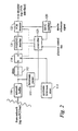
- a multiple source video system comprises a video pump 10a supplying coded real-time video to a decoder 20a, and receiving coded video data from a storage medium 30a.
- the video pump 10a and a second video pump 10b supplying a second decoder 20b are both connected to the storage medium 30a (for example a computer file server) over a computer network.
- This embodiment also includes a third video pump 10c supplying a third decoder 20c and receiving data from a dedicated data source 30b, and a fourth video pump 10d receiving "live" coded video via an off-air receiver 32 which includes a demultiplexer for extracting a single programme stream from the received data and buffer 34 having a capacity sufficient to store several minutes (here about 30 minutes) of video data, the fourth video pump supplying a fourth decoder 20d.
- the outputs of all decoders are connected to a selector 40 which selects an output from one of the decoders; the output may be broadcast (either in analogue or digital form), or may be stored or recoded.
- the decoders produce an output in decoded digital form including information concerning coding decisions based on the original coded video (MOLE format), to enable re-coding with minimum loss of quality.
- MOLE format original coded video
- other decoding for example to full analogue may be employed.
- each video pump receives a timing signal from a studio reference clock 12.
- the studio reference clock typically supplies a 42 bit SSTC counter value based on a 27MHz clock, comprising a 33 bit 90kHz (equal to the clock frequency divided by 300) base value and a 9-bit (modulo 300) extension value clocked at 27MHz.
- the clock 12 also converts the 42 bit studio reference clock times into SMPTE time codes and supplies both along a common bus at regular intervals.
- Each video pump also receives playout decision information from an edit/playout controller 14.
- the edit/playout controller typically specifies edit/playout times in SMPTE codes.
- the SSTC and related SMPTE time values can be supplied separately, but preferably the SSTC bus provides information enabling correlating the two.
- the studio clock values may be converted into SMPTE values, and it is not necessary to supply SMPTE values if the corresponding studio clock counter values are supplied by the playout controller.
- Editing or playout decisions may be specified in advance, for example as a play schedule for a period of time (for example: "At 9.00pm and 15.0 seconds, play the video sequence entitled 'Film A' commencing at Frame 0 via video pump 10a"), or may be modified or set in real-time. For example, an immediate request to play a sequence may be translated into a request to commence playing in exactly 5 seconds time.
- the editing or playout decision information is sent to both the selector 40 and the video pumps 10.
- a video pump only has access to a single coded video source, for example the video pump 10d receiving a single buffered off-air video sequence
- the editing information need not specify the description of the source; otherwise, the description of the source may be sent to the video pump which may request the appropriate data from the storage medium, or may be sent directly to the storage medium.
- the selector simply switches the output from one source to another at the specified time, and may be entirely conventional.
- the appropriate video pump determines when the coded video sequence must be played, and how to ensure synchronisation so that the decoder is producing the correct output at the time of the switch. This can be achieved in a number of ways, as will be described in more detail below.
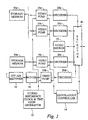
- a coded video source a "video pump” 10
- a data input for example a computer network
- a network buffer 110 which smooths discontinuities in the time of arrival of the data resulting from server and network latency.
- the precise method of feeding data to the network buffer is not critical, and forms of itself no part of the present invention; any suitable protocol used in similar computer networks may be used, provided of course that the buffer always contains enough data for the output to be maintained.
- the apparatus will be controlled by a computer, which will also control the feeding of data from a network server or disk.
- the data is fed to a bitstream parser 111, which detects appropriate fields in the video and system layers for re-stamping and for switching to synthetic streams.
- the data is also fed to a delay 112, which compensates for the delay in the bitstream parser 111.
- a synthetic bitstream store 113 contains versions of synthetic video bitstreams in an appropriate form.
- a switch 114 is fed with the data from the delay 112 and from the synthetic bitstream store 113, and selects between these sources, ie between the input and synthetic bitstreams.
- a studio system time clock (SSTC) 120 provides a count which can be inserted in PCR fields such that the decoder will synchronize to studio time.
- the bitstream emerging from the switch 114 is fed to a unit 121, which re-stamps the fields mentioned above, including in particular the PTS/DTS fields.
- the bitstream then passes to a unit 122, which re-stamps the PCR fields. This is shown as a separate final block in the bitstream, because there must be a minimum of timing jitter between the insertion of the PCR fields and the reception of these fields by the decoder.
- a controller 123 is fed with commands from a play-out control list and by the local SSTC counter 120. This controller controls the following functions:
- the interface hardware 121 and 122 re-stamps PCR and PTS/DTS fields for both synthetic and image bitstreams.
- the values inserted in the PCR fields are such that the following decoder will have an internal decoder clock count which is synchronized to a similar count in the studio. This enables the presentation/display times of particular decoded frames to be synchronized to precise studio times.
- the PTS/DTS values are re-stamped with appropriate values, as described more fully below, in relation to the decoder clock count (DCC) such that:
- Continuity of PTS/DTS values may be set by adding an offset to the values in the original coded video sequence; for example, if the first PCR/PTS/DTS value is modified from a value x (stored in the coded video, based on the original coder counter value) to a value y (based on the studio reference clock), all subsequent values may be modified simply by adding an offset (which may be positive or negative) of (x-y) to the incoming values.
- the data output rate, or timing of outputting of coded frame data must be set so that the decoder buffer does not overflow or underflow.
- some features may be omitted; for example, if it is merely desired to synchronise an output clock frequency to a studio reference clock, the means for generating synthetic frames may be omitted. Similarly, if precise timing of the decoder output is not required, the studio reference clock input may be omitted, the apparatus still being capable of generating bitstreams adapted for pre-synchronising of a decoder or pausing or slow-motion playback. Most flexibility is, however, assured if the above features are included together.
- Each decoder has its own clock, typically running at 27MHz, producing a Decoder Clock Count (DCC) value which increments at a similar rate to the PCR values in the original data. Owing to tolerances, there may be a gradual drift between a DCC and the original coder clock values, which might accumulate.
- DCC Decoder Clock Count
- the coder may send with a frame a DTS value specifying the time at which the frame should be extracted from the decoder buffer for decoding and a PTS value specifying the time at which the decoded frame should be displayed.
- DTS and PTS are identical; for I and P frames, which are stored in the decoder, the DTS precedes the PTS.
- the PCR values in the original data stream are replaced by values based on the studio reference clock.
- the DTS and PTS fields may be used to specify an absolute time.
- display of a frame at a particular time may be effected simply by setting the PTS field to the appropriate time (in practice, this may differ in practice from the actual output time due to output delays in a practical decoder, so the apparatus may include means for storing an offset value to be added to or subtracted from values written into this field).
- a complication is that the PTS and DTS fields are not obligatory for every frame, and not all decoders may use them, particularly after synchronisation is first established.
- the vbv_delay field may be used; this specifies the delay before a frame, particularly an I frame, can be read from the decoder buffer. It will be realized that the vbv_delay can actually be determined from this more general timing; this time is the difference between the time when the frame is received and the time when the frame is removed from the buffer for decoding.
- vbv_delay DTS - DCC(frame write)
- the decoder should use the DTS to determine the vbv_delay if the DTS is available; if there is no DTS available, then it should use the vbv_delay value from the frame header.
- the vbv_delay value may not be explicitly specified (in an MPEG sequence, a vbv_delay field containing 0xFF throughout signifies no specified value) in the video layer, in which case an effective vbv_delay may be calculated based on the DTS field in the PES layer and the actual time of writing of the frame.
- references to an effective vbv_delay value are intended to encompass any such parameters or combinations of parameters which determine the residency time of a frame within a decoder buffer.
- the generated frames are preferably of relatively low information content (as compared to a typical picture frame), so that writing and reading the frames takes relatively little time.
- the average data content of each generated frame is at most equal to the amount of data that can be written in a single frame display period, and preferably substantially less (for example at most half).
- a black I frame, or an I frame containing a simple logo (by which is meant a picture the coding of which requires relatively little data compared to an average real picture scene, preferably an amount of data that can be transmitted in approximately a single frame period or less), or a P frame encoding no motion, may be used.
- the initial I frame may contain more data than can be sent in a single frame period, but the average data rate for a sequence containing the I frame and one or more P frames will be below the required rate. In this way, frames can be output at an average rate of one frame per frame period and there is flexibility to insert generated frames for prolonged periods without running into buffer underflow and overflow problems, and without recourse to complex buffer occupancy determining methods.
- output of the generated sequence may make it possible to "buy time” in which to output data for a larger frame.
- the decoder buffer contains data for several synthetic frames to be output, so that the decoder buffer always contains frames for display.
- a simple synthetic black I-frame may be summarised as follows: Prediction mode Intra Frame/Field DCT mode Frame mode (either could be used) Coefficient values All zero including DC coefficient (for black I frame) Picture size Value taken from associated image sequence vbv-delay Value taken from first I frame of following sequence elementary stream bit-rate Value taken as max, from associated image sequences Temporal Reference Set to zero assuming I frame follows GOP header
- the I-frame could be coded as a black I/P field pair.
- the video elementary stream is first packetised into PES packets . These can have many optional fields in the header of each PES packet.
- the PES packet header is preferably as simple as possible with as few optional fields as possible. Also, it would be convenient to contain each coded frame (access unit) within a single PES packet.
- a suitable synthetic bitstream to effect initial decoder synchronisation consists of a black I-frame followed by a sequence of synthetic (null) P-frames.
- the initial frame need not be black, but may contain a simple logo.
- several such sequences may be transmitted. Although such a sequence may only be transmitted a few frames or a few seconds before start of the desired sequence is required, it is equally possible to transmit such a sequence for prolonged periods of time, for example several hours, to keep a decoder synchronised over a prolonged period of time. In such cases, the decoder may also be "paused" in the synchronised state (as discussed further below).
- B frames are not stored in the decoder and are decoded and output without delay, whereas I and P frames needed to decode B frames are normally output in advance of display time.
- B frames have not been numbered; each B frame in the display sequence corresponds directly to the B frame vertically above in the bitstream sequence.
- DTS(I 0 ) PTS(I 0 ) - (n B +1).T where T is the video frame period.
- Video data can be sent to the decoder either as a constant bit-rate (CBR) stream or as a variable bit-rate (VBR) stream.
- CBR constant bit-rate
- VBR variable bit-rate
- the total bit-rate of the transport stream may be maintained at a constant rate by sending "null" transport stream packets as required.
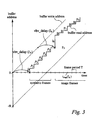
- FIG. 3 A diagram showing an example of the write and read addresses of the decoder buffer in CBR operation is shown in Figure 3.
- a buffer is in practice accessed cyclically,with wraparound; when a read or write pointer reaches the end of the buffer (address B, where B is the buffer size), it returns to the beginning.
- the buffer addresses are shown as linearly increasing in Figure 3 (and the subsequent figures); the real addresses will be equal to the indicated address modulo B (i.e. an addresses of B+x is equivalent to an address of x, where is an integer and x ⁇ B).
- each coded synthetic frame is padded with stuffing bytes such that each frame takes one frame interval to be fed to the decoder at the CBR bit-rate.
- the vbv-delay for the first synthetic frame is arranged to be equal to the vbv_delay of the first I frame of the image sequence. This allows CBR mode to be maintained.
- VBR operation we can consider the case where the pre-coded image sequence has a fixed and constant bit-rate but the bit-rate of the synthetic video data fed to the video decoder is allowed to be less than this constant value.
- a simple approach is to arrange that the synthetic data is fed to the decoder at a rate of one synthetic frame per frame period.
- the data for the first synthetic frame is assigned an appropriate DTS value and fed to the decoder buffer at a time (given by Eqn 7) such that its vbv_delay value is equal to the vbv_delay of the first I frame of the sequence. Then the remaining synthetic frames are fed at a rate of one frame per frame period. At time, t trans (0), the first I frame of the sequence is sent and the vbv_delay value for this frame will be correct.
- Figure 4 shows that the decoder buffer does not under-flow.
- Synthetic bitstreams can be used to pause a decoder at certain points in the sequence.
- a suitable synthetic sequence comprises a null series of P-frames. For example, suppose a series of synthetic P frames is inserted before a P-frame as shown below
- the decoder Whilst the decoder is decoding the synthetic P frames, it will continue to display the last decoded "anchor" frame which in this example is frame P 1 . Since the B-frames are not stored in the decoder these cannot be repeated. Following the sequence of synthetic P-frames, the image sequence can be continued.
- a synthetic P-frame sequence can be used in a similar manner for pausing a decoder after an I-frame, thereby providing a means of displaying a still image.
- I-frames into the sequence, for example black I frames, to ensure that synchronisation is not inadvertently lost.
- Synthetic sequences can also be used to help in the splicing together of different bitstreams using an approach very similar to that described for decoder initialisation and pausing; a splice using this approach can be considered similar to pausing of a decoder and establishing synchronisation to a new bitstream in a combined operation.
- the "rule" of sending one synthetic frame per frame period is not maintained for this application.
- a common requirement could be to switch (in real time) to a second sequence bitstream at some fairly arbitrary point in a first sequence bitstream without causing a downstream decoder any significant disturbance.
- the main problem here is matching the decoder buffer occupancy at the point of leaving the first sequence to the buffer occupancy required before the first coded frame of the second sequence. If these are not matched then the decoder buffer will over or under flow which will cause a significant disturbance to the decoded image sequence.
- Bitstream1 I 0 B B P 1 B B P 2 B B P 3 B B P 4 B B P 5 B B
- Bitstream2 I 0 B B P 1 B B P 2 B B P 3 Spliced stream I 0 B B P 1 B B P P P P I 0 B B P 1 B B P 2 B B P 3
- Bitstream2 I 0 B B P 1 P 1 P 1 B B I 0 B B P 1 B B P 2 B B P 3
- the vbv_delay value for I 0 of bitstream 2 will be greater than the vbv_delay value for frame P 2 of bitstreaml.
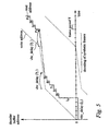
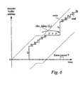
- the synthetic bitstreams contain an almost negligible number of bits, it is possible to transmit these in a short period of time and then advance the time at which the first byte of frame I 0 is fed to the decoder. In this way it is possible to achieve the correct vbv_delay value for I 0 . This is illustrated in Figure 6.
- the video output apparatus can provide other functions. For example, even without the means for generating synthetic frames, synchronisation to a studio reference clock can be effected, as discussed below.
- a stored MPEG video sequence contains a series of PCR fields, each field containing a clock value which increments at the clock rate (typically 27MHz) of the original capture apparatus when the sequence is played at the correct bit-rate.
- the correct bit rate will usually be specified with the stored data, and conventionally a video source simply plays the data out at the specified rate. For example a sequence may have been captured at 4 Mbit/s, and a conventional video source will simply output the data at that rate, based on its own clock source. However when played back at 4 Mbit/s, it may be found that the PCR values increment at a rate slightly greater or less than 27 MHz, for example due to inaccuracies in the recording apparatus clock frequency.
- This can be detected by comparing the rate at which PCR values increase to a studio clock reference frequency, and can be corrected by adjusting the data output rate so that a counter updated at the same rate as the PCR values in the recorded video sequence maintains synchronism with the studio reference clock.
- the invention has many applications, and can be extended to applications other than those described above.
- An example of another application of the invention is the "repair" or editing of corrupted video sequences by re-generating timing field values, or patching synthetic frames in to over-write corrupted data.
- the same techniques may be applied to other coded data supplied as a sequence of coded frames; in particular, synthetic coded audio frames and synchronisation of coded (e.g. MPEG) audio may be effected.
- MPEG format is most commonly employed to transmit data including video data
- MPEG audio/visual/data sequence containing no video the invention may be employed to establish synchronisation for the purposes of playing out of audio or data contained within the sequence.
- the format of the synthetic frames will, of course change; specifically, null frames will usually be employed as padding.
- video as used throughout the description and claims may be replaced by audio or data as required.
Landscapes
- Engineering & Computer Science (AREA)
- Multimedia (AREA)
- Signal Processing (AREA)
- Physics & Mathematics (AREA)
- General Physics & Mathematics (AREA)
- Discrete Mathematics (AREA)
- Theoretical Computer Science (AREA)
- Business, Economics & Management (AREA)
- Marketing (AREA)
- Compression Or Coding Systems Of Tv Signals (AREA)
- Television Systems (AREA)
Claims (40)
- Appareil pour synchroniser les sorties d'au moins deux décodeurs en temps réel, chacun adapté pour recevoir un flux binaire vidéo codé par compression respectif, pour décoder le flux binaire et pour fournir une séquence d'images à des temps de sortie déterminés par des valeurs dans le flux binaire, l'appareil comprenant :caractérisé par :un moyen (110) pour recevoir chaque flux binaire vidéo codé par compression ;un moyen (122) pour fournir chaque flux binaire vidéo codé par compression ;un moyen (120) pour recevoir une horloge de référence de studio ;un moyen pour spécifier un temps prédéterminé de sortie par rapport à ladite horloge de référence de studio ;un moyen pour traiter chaque flux binaire vidéo codé par compression en fonction d'informations de relation de temps dérivées de l'horloge de référence de studio pour qu'un décodeur recevant le flux binaire vidéo codé de sortie produise des images décodées à ladite relation de temps prédéterminée de sortie.
- Appareil selon la revendication 1, dans lequel ledit moyen de traitement sert à changer une ou plusieurs desdites valeurs.
- Appareil selon la revendication 1, dans lequel ledit moyen de traitement sert à ajuster le temps de ladite fourniture sur la base d'une ou plusieurs desdites valeurs.
- Appareil selon la revendication 2, dans lequel la séquence est une séquence vidéo MPEG, ledit traitement comprenant un changement des valeurs d'au moins un des champs PCR, PTS, et DTS.
- Appareil selon la revendication 3, dans lequel la séquence est une séquence vidéo MPEG et dans lequel ledit ajustement est basé sur des valeurs comprenant au moins un retard vbv (vbv_delay) ou une combinaison des paramètres qui détermine le temps de résidence d'une trame dans le tampon de décodeur.
- Appareil selon la revendication 2 dans lequel le moyen pour déterminer un retard entre un commencement de la sortie des données correspondant à une trame par ledit moyen de fourniture et un affichage de la trame par un décodeur, ledit moyen d'ajustement étant commandé en fonction du retard déterminé.
- Appareil selon la revendication 6 dans lequel ledit moyen pour ajuster la relation de temps est agencé pour commencer à fournir des données correspondant à la trame à un temps égal au temps d'affichage souhaité pour cette trame moins un temps de retard déterminé.
- Appareil selon la revendication 7 dans lequel le moyen pour déterminer ledit temps de retard sur la base d'une valeur de décalage prédéterminée correspondant à une mesure de retard de propagation à travers ledit décodeur et une valeur variable correspondant à un retard avant de décoder ladite trame.
- Appareil selon l'une quelconque des revendications précédentes ayant un moyen pour appliquer des informations spécifiant une mesure de temps souhaité de sortie d'image d'au moins une trame ou un champ d'une séquence vidéo ou d'une valeur DTS ou PTS, ledit traitement étant basé sur. la mesure du temps souhaité de sortie d'image et l'horloge de référence de studio pour qu'au moins une trame ou un champ soit fourni par un décodeur à un temps souhaité de sortie d'image.
- Appareil selon les revendications 2 et 3.
- Appareil selon l'une quelconque des revendications précédentes ayant un moyen pour déterminer une fréquence d'horloge efficace pour la sortie du flux binaire vidéo codé sur la base du taux de variation des valeurs d'horloge contenues dans les données de sortie et un moyen pour comparer et synchroniser la fréquence d'horloge efficace à la fréquence d'horloge de référence de studio.
- Appareil selon l'une quelconque des revendications 1 à 10 comprenant un moyen pour générer une séquence d'une ou plusieurs trames à insérer dans le flux binaire de sortie et un moyen pour insérer la séquence générée dans ledit flux binaire vidéo codé pour ajuster les relations de temps des images de sortie, la séquence générée étant sélectionnée pour maintenir ou établir une synchronisation d'un tampon d'un décodeur recevant le flux binaire de sortie.
- Appareil selon la revendication 12 agencé pour insérer la séquence générée devant une trame donnée dudit flux binaire vidéo codé, la taille des informations de trames et/ou de relation de temps générées, ou le temps de sortie des données, associées à ladite trame séquence générée et/ou donnée étant sélectionnée pour qu'au début du décodage de ladite trame donnée après le décodage de la séquence générée, l'occupation de tampon d'un décodeur recevant ledit flux binaire vidéo de sortie soit sensiblement égale à une valeur souhaitée.
- Appareil selon la revendication 13 agencé pour insérer la séquence générée devant ladite trame donnée et après au moins une trame précédente dans le flux binaire vidéo codé, dans lequel la valeur souhaitée de l'occupation de tampon est rendue sensiblement égale à l'occupation de tampon attendue si aucune séquence générée n'était insérée entre la trame précédente et ladite trame donnée.
- Appareil selon la revendication 13 ou 14 agencé pour générer une séquence comprenant une ou plusieurs trames d'un contenu d'informations relativement bas, et dans lequel des informations de relation de temps sont réglées pour que des données pour la première trame générée restent dans le tampon du décodeur avant de décoder sensiblement le temps spécifié dans le flux binaire vidéo codé pour des données pour ladite trame donnée de la séquence vidéo, et des trames générées par la suite sont fournies à un débit moyen sensiblement égal au débit d'affichage de ces trames, dans lequel la séquence vidéo est de préférence une séquence MPEG, la valeur effective de retard vbv pour la première trame générée étant réglée égale à la valeur effective de retard vbv pour ladite trame donnée.
- Appareil selon la revendication 13, 14 ou 15 agencé pour établir une synchronisation initiale de décodeur à une séquence vidéo codée comprenant une séquence MPEG, dans lequel la séquence générée comprend au moins une trame I.
- Appareil selon la revendication 13, 14 ou 15 agencé pour effectuer la mise en pause ou la lecture au ralenti d'une séquence vidéo codée comprenant une séquence MPEG, dans lequel la séquence générée comprend une ou plusieurs trames P.
- Appareil selon la revendication 13, 14 ou 15 agencé pour faciliter la commutation d'un flux binaire vidéo de sortie d'un premier flux binaire vidéo codé à un second flux binaire vidéo codé, dans lequel la taille des informations de trames générées et/ou de relation de temps associées aux trames générées et/ou aux trames desdits premier et second flux binaires vidéo codés sont sélectionnées pour qu'au début du décodage du second flux binaire vidéo codé après ladite commutation, l'occupation du tampon d'un décodeur recevant ledit flux binaire vidéo de sortie soit sensiblement égale à une valeur souhaitée.
- Appareil selon la revendication 18 dans lequel la valeur souhaitée de l'occupation de tampon est déterminée sur la base d'une estimation de l'occupation de tampon si le décodeur avait reçu le second flux binaire vidéo codé à la place du premier flux binaire vidéo codé et du flux binaire généré.
- Appareil selon l'une quelconque des revendications précédentes comprenant en outre un moyen pour recevoir des informations de liste d'édition spécifiant un temps souhaité de sortie d'image.
- Appareil selon l'une quelconque des revendications précédentes comprenant en outre un moyen pour recevoir des informations d'édition ou de lecture spécifiant des relations de temps de variations entre des sources de séquence vidéo ;
un moyen pour fournir une source de séquence vidéo sélectionnée sur un canal de sortie vidéo sur la base desdites informations d'édition ou de lecture ; et
un moyen pour fournir des informations de temps souhaité de sortie d'image vers le ou chaque appareil de sortie sur la basé desdites informations d'édition. - Procédé pour synchroniser les sorties d'au moins deux décodeurs en temps réel, chacun adapté pour recevoir un flux binaire vidéo codé par compression respectif, pour décoder le flux binaire et pour fournir une séquence d'images à des temps de sortie déterminés par des valeurs dans le flux binaire, le procédé comprenant les étapes de :réception de chaque flux binaire vidéo codé ;réception d'une horloge de référence de studio ;spécification d'une relation de temps de sortie prédéterminée par rapport à ladite horloge de référence de studio ;traitement de chaque flux binaire vidéo codé en fonction des informations de relation de temps dérivées de l'horloge de référence de studio pour qu'un décodeur recevant le flux binaire vidéo codé de sortie produise une sortie d'image décodée à ladite relation de temps prédéterminée de sortie.
- Procédé selon la revendication 22, dans lequel ledit traitement comprend un changement d'une ou de plusieurs desdites valeurs vidéo.
- Procédé selon la revendication 22, dans lequel ledit traitement comprend un ajustement de temps de ladite sortie sur la base d'une ou de plusieurs desdites valeurs.
- Procédé selon la revendication 23, dans lequel le flux binaire est un flux vidéo MPEG, ledit traitement comprenant des valeurs de changement d'au moins un des champs PCR, PTS, et DTS.
- Procédé selon la revendication 22 comprenant la détermination d'un retard entre un commencement de la sortie des données correspondant à une trame et l'affichage de la trame par un décodeur, le traitement étant commandé en fonction du retard déterminé.
- Procédé selon la revendication 22, dans lequel le flux binaire est un flux vidéo MPEG, dans lequel le temps auquel les données correspondant à au moins une trame ou à un champ est fourni, est ajusté sur la base des valeurs comprenant au moins un retard vbv ou une combinaison des paramètres qui déterminent le temps de résidence d'une trame dans le tampon de décodeur.
- Procédé selon la revendication 27 dans lequel l'ajustement de la relation de temps est agencé pour commencer la sortie des données correspondant à au moins une dite trame à un temps égal au temps souhaité d'affichage pour cette trame moins le temps de retard déterminé.
- Procédé selon la revendication 28 comprenant en outre une détermination dudit temps de retard sur la base d'une valeur prédéterminée de décalage correspondant à une mesure du retard de propagation à travers ledit décodeur et à une valeur variable correspondant au retard avant décodage de ladite trame.
- Procédé selon l'une quelconque des revendications 22 à 29 comprenant une détermination d'une fréquence d'horloge efficace pour le flux binaire vidéo codé de sortie sur la base du taux de variation des valeurs d'horloge contenues dans les données de sortie, et une comparaison ou une synchronisation de la fréquence d'horloge efficace à la fréquence d'horloge de référence de studio.
- Procédé selon l'une quelconque des revendications 22 à 30 comprenant une génération d'une séquence d'une ou plusieurs trames à insérer dans le flux binaire de sortie, et une insertion de la séquence générée dans ledit flux binaire vidéo codé pour ajuster la relation de temps de la sortie d'image, la séquence générée étant sélectionnée pour maintenir ou établir la synchronisation d'un tampon d'un décodeur recevant le flux binaire de sortie.
- Procédé selon la revendication 31 dans lequel la séquence générée est insérée avant une trame donnée dudit flux binaire vidéo codé, la taille des informations des trames générées et/ou de relation de temps, ou le temps de sortie des données, associé à la trame générée et/ou ladite trame donnée étant sélectionnés pour qu'au début du décodage de ladite trame donnée après le décodage de la séquence générée, l'occupation de tampon d'un décodeur recevant ledit flux binaire vidéo de sortie soit sensiblement égale à une valeur souhaitée.
- Procédé selon la revendication 32 dans lequel la séquence générée est insérée avant ladite trame donnée et après au moins une trame précédente dans le flux binaire vidéo codé, dans lequel la valeur souhaitée de l'occupation de tampon est réglée sensiblement égale à l'occupation de tampon attendue si aucune séquence générée n'était insérée entre la trame précédente et ladite trame donnée.
- Procédé selon la revendication 32 ou 33 dans lequel une séquence comprenant une ou plusieurs trames de contenu d'informations relativement basses sont générées, et dans lequel des valeurs de relation de temps sont réglées pour que des données pour la première trame générée restent dans le tampon de décodeur avant le décodage sensiblement pendant le temps spécifié dans le flux binaire vidéo codé pour des données pour ladite trame donnée du flux binaire vidéo, et des trames générées par la suite sont fournies à un débit moyen sensiblement égal au débit d'affichage de ces trames.
- Procédé selon la revendication 34 dans lequel le flux binaire vidéo est un flux binaire MPEG, la valeur effective de retard vbv pour la première trame générée étant rendue égale à la valeur effective de retard vbv pour ladite trame donnée.
- Procédé selon l'une quelconque des revendications 31 à 35 pour établir une synchronisation initiale de décodeur avec un flux binaire vidéo codé comprenant un flux binaire MPEG, dans. lequel la séquence générée comprend au moins une trame I.
- Procédé selon l'une quelconque des revendications 31 à 35 pour effectuer une mise en pause ou une lecture au ralenti d'un flux binaire vidéo codé comprenant un flux binaire MPEG, dans lequel la séquence générée comprend une ou plusieurs trames P.
- Procédé selon l'une quelconque des revendications 31 à 35 pour faciliter une commutation d'un flux binaire vidéo de sortie d'un premier flux binaire vidéo codé à un second flux binaire vidéo codé, dans lequel la taille des informations de trames générées et/ou de relation de temps associée aux trames générées et/ou aux trames dans lesdits premier et second flux binaires vidéo codés sont sélectionnés pour qu'au début du décodage du second flux binaire vidéo codé après ladite commutation, l'occupation de tampon d'un décodeur recevant ledit flux binaire vidéo de sortie soit sensiblement égale à une valeur souhaitée.
- Procédé selon la revendication 38 dans lequel la valeur souhaitée de l'occupation de tampon est déterminée sur la base d'une estimation de l'occupation de tampon si le décodeur avait reçu le second flux binaire vidéo codé au lieu du premier flux binaire vidéo codé et de la séquence générée.
- Procédé de commande d'un système vidéo de source multiple comprenant un appareil selon l'une quelconque des revendications 1 à 21 et au moins deux décodeurs raccordés à celui-ci, le procédé comprenant :la fourniture d'une horloge de référence de studio à l'appareil ;la réception d'informations d'édition et de lecture spécifiant les temps de variation entre des sources de séquence vidéo ;la sélection d'un desdits décodeurs comme une source vidéo pour fournir un canal de sortie vidéo sur la base desdites informations d'édition ;la fourniture des informations de temps souhaité de sortie d'image vers l'appareil ou chaque appareil de sortie sur la base desdites informations d'édition ou de lecture ; etla commande de l'appareil sur la base de ladite horloge de référence de studio et ledit temps souhaité de sortie d'image pour qu'une sortie souhaitée d'image soit disponible à partir de chaque décodeur au moment où la sortie de décodeur est sélectionnée comme ladite source vidéo.
Applications Claiming Priority (3)
| Application Number | Priority Date | Filing Date | Title |
|---|---|---|---|
| GB9716896A GB2328099B (en) | 1997-08-08 | 1997-08-08 | Processing coded video |
| GB9716896 | 1997-08-08 | ||
| PCT/GB1998/002397 WO1999008441A2 (fr) | 1997-08-08 | 1998-08-10 | Traitement de signaux video codes |
Publications (2)
| Publication Number | Publication Date |
|---|---|
| EP1002424A2 EP1002424A2 (fr) | 2000-05-24 |
| EP1002424B1 true EP1002424B1 (fr) | 2003-05-14 |
Family
ID=10817258
Family Applications (1)
| Application Number | Title | Priority Date | Filing Date |
|---|---|---|---|
| EP98938775A Expired - Lifetime EP1002424B1 (fr) | 1997-08-08 | 1998-08-10 | Traitement de signaux video codes |
Country Status (9)
| Country | Link |
|---|---|
| US (1) | US6741290B1 (fr) |
| EP (1) | EP1002424B1 (fr) |
| JP (1) | JP2001513606A (fr) |
| AU (1) | AU754879B2 (fr) |
| CA (1) | CA2300389A1 (fr) |
| DE (1) | DE69814642T2 (fr) |
| ES (1) | ES2194338T3 (fr) |
| GB (1) | GB2328099B (fr) |
| WO (1) | WO1999008441A2 (fr) |
Cited By (1)
| Publication number | Priority date | Publication date | Assignee | Title |
|---|---|---|---|---|
| CN1998239B (zh) * | 2004-07-01 | 2011-11-30 | 奥伊加梅克拉斯特公司 | 向解码器提供数据的方法和设备 |
Families Citing this family (38)
| Publication number | Priority date | Publication date | Assignee | Title |
|---|---|---|---|---|
| FR2795272B1 (fr) * | 1999-06-18 | 2001-07-20 | Thomson Multimedia Sa | Procede de commutation de flux mpeg |
| US6970510B1 (en) * | 2000-04-25 | 2005-11-29 | Wee Susie J | Method for downstream editing of compressed video |
| JP4734690B2 (ja) * | 2000-04-28 | 2011-07-27 | ソニー株式会社 | 信号送出方法及び信号送出装置 |
| JP2004505513A (ja) * | 2000-07-25 | 2004-02-19 | エイジルビジョン・エル・エル・シー | ネットワークフィードの固定タイムスロットに圧縮されたローカルビデオセグメントをスプライシングすること |
| US6766376B2 (en) | 2000-09-12 | 2004-07-20 | Sn Acquisition, L.L.C | Streaming media buffering system |
| US6594316B2 (en) * | 2000-12-12 | 2003-07-15 | Scientific-Atlanta, Inc. | Method and apparatus for adaptive bit rate control in an asynchronized encoding system |
| CN1269363C (zh) * | 2001-07-27 | 2006-08-09 | 松下电器产业株式会社 | 数字广播系统、同步信息替换装置和方法 |
| US6959044B1 (en) * | 2001-08-21 | 2005-10-25 | Cisco Systems Canada Co. | Dynamic GOP system and method for digital video encoding |
| US20030066094A1 (en) * | 2001-09-29 | 2003-04-03 | Koninklijke Philips Electronics N.V. | Robust method for recovering a program time base in MPEG-2 transport streams and achieving audio/video sychronization |
| EP1333677A1 (fr) * | 2002-01-31 | 2003-08-06 | BRITISH TELECOMMUNICATIONS public limited company | Vidéo-codage |
| US7764863B1 (en) * | 2002-03-06 | 2010-07-27 | Bigband Networks Inc. | System and method for providing trick modes |
| US7315622B2 (en) * | 2002-06-27 | 2008-01-01 | Nxp B.V. | Robust method for achieving audio/video synchronization in MPEG decoders in personal video recording applications |
| US7693399B2 (en) * | 2002-07-11 | 2010-04-06 | Lg Electronics Inc. | Method for providing program specific information recorded on high density disc medium |
| US7787539B2 (en) * | 2002-07-17 | 2010-08-31 | Broadcom Corporation | Decoding and presentation time stamps for MPEG-4 advanced video coding |
| JP3513148B1 (ja) * | 2002-10-11 | 2004-03-31 | 株式会社エヌ・ティ・ティ・ドコモ | 動画像符号化方法、動画像復号方法、動画像符号化装置、動画像復号装置、動画像符号化プログラム、及び動画像復号プログラム |
| JP3909704B2 (ja) * | 2003-04-04 | 2007-04-25 | ソニー株式会社 | 編集システム |
| US9456243B1 (en) | 2003-06-06 | 2016-09-27 | Arris Enterprises, Inc. | Methods and apparatus for processing time-based content |
| US7680155B2 (en) * | 2003-08-14 | 2010-03-16 | Zenith Electronics Llc | PCR jitter reduction in a VSB and/or EVSB multiplexer system |
| US7983835B2 (en) | 2004-11-03 | 2011-07-19 | Lagassey Paul J | Modular intelligent transportation system |
| US8190680B2 (en) * | 2004-07-01 | 2012-05-29 | Netgear, Inc. | Method and system for synchronization of digital media playback |
| US8233540B2 (en) * | 2005-03-10 | 2012-07-31 | Qualcomm Incorporated | Method of time base reconstruction for discrete time labeled video |
| KR100638138B1 (ko) * | 2005-05-24 | 2006-10-24 | 주식회사 픽스트리 | 비디오/오디오 부호화 및 다중화 기능을 가진 하드웨어장치 및 그 작동 방법 |
| TWI294085B (en) * | 2005-07-12 | 2008-03-01 | Realtek Semiconductor Corp | Method and apparatus for synchronizing multimedia data stream |
| WO2007072252A2 (fr) * | 2005-12-23 | 2007-06-28 | Koninklijke Philips Electronics N.V. | Dispositif et procédé de traitement d'un flux de données d'entrée comprenant une séquence de trames d'entrée |
| WO2008036949A2 (fr) * | 2006-09-22 | 2008-03-27 | Eg Technology. Inc. | Procédés et systèmes pour la correction de base de temps d'un flux de transport |
| US20080129361A1 (en) * | 2006-12-05 | 2008-06-05 | Rajesh Mamidwar | Method and system for programmable delays on transport outputs |
| US8966103B2 (en) * | 2007-12-21 | 2015-02-24 | General Instrument Corporation | Methods and system for processing time-based content |
| US8194756B2 (en) * | 2008-05-28 | 2012-06-05 | Broadcom Corporation | Using program clock references to assist in transport of video stream to wireless device |
| US20100043038A1 (en) * | 2008-08-14 | 2010-02-18 | Zoran Corporation | System and method for efficient video and audio instant replay for digital television |
| CN101500117A (zh) * | 2009-02-18 | 2009-08-05 | 腾讯科技(深圳)有限公司 | 一种视音频数据播放的控制方法及装置 |
| US8606073B2 (en) | 2010-05-12 | 2013-12-10 | Woodman Labs, Inc. | Broadcast management system |
| US8643696B2 (en) * | 2011-01-19 | 2014-02-04 | Broadcom Corporation | Synchronizing media streams using time signal(s) from an independent time source |
| KR20130003544A (ko) * | 2011-06-30 | 2013-01-09 | 한국전자통신연구원 | 단말 장치들 사이의 콘텐츠 동기화 방법 및 시스템 |
| US20150062353A1 (en) * | 2013-08-30 | 2015-03-05 | Microsoft Corporation | Audio video playback synchronization for encoded media |
| KR20170068946A (ko) * | 2015-12-10 | 2017-06-20 | 삼성전자주식회사 | 방송 수신 장치 및 방송 수신 장치의 제어 방법 |
| CN106507202B (zh) * | 2016-11-11 | 2019-12-17 | 传线网络科技(上海)有限公司 | 播放控制方法及装置 |
| US11736755B2 (en) * | 2018-04-24 | 2023-08-22 | Google Llc | Methods, systems, and media for synchronized media content playback on multiple devices |
| US11316912B2 (en) * | 2020-05-26 | 2022-04-26 | Grass Valley Canada | System and method for synchronizing transmission of media content using timestamps |
Family Cites Families (14)
| Publication number | Priority date | Publication date | Assignee | Title |
|---|---|---|---|---|
| US4947256A (en) * | 1989-04-26 | 1990-08-07 | The Grass Valley Group, Inc. | Adaptive architecture for video effects |
| KR0121301B1 (ko) * | 1992-09-30 | 1997-11-17 | 사또오 후미오 | 편집신호 디코딩 장치 |
| JPH07212766A (ja) * | 1994-01-18 | 1995-08-11 | Matsushita Electric Ind Co Ltd | 動画像圧縮データ切り換え装置 |
| DE69515386T2 (de) * | 1994-07-15 | 2000-08-24 | Matsushita Electric Industrial Co., Ltd. | Verfahren zur Verbindung von MPEG-Videosequenzen |
| US5534944A (en) * | 1994-07-15 | 1996-07-09 | Matsushita Electric Corporation Of America | Method of splicing MPEG encoded video |
| JP3371174B2 (ja) * | 1994-09-22 | 2003-01-27 | ソニー株式会社 | パケット受信装置 |
| US5652627A (en) * | 1994-09-27 | 1997-07-29 | Lucent Technologies Inc. | System and method for reducing jitter in a packet-based transmission network |
| US5828841A (en) * | 1994-10-31 | 1998-10-27 | Sony Corporation | Video signal recording and reproduction apparatus |
| JP3575100B2 (ja) * | 1994-11-14 | 2004-10-06 | ソニー株式会社 | データ送信/受信装置及び方法並びにデータ記録/再生装置及び方法 |
| GB9424429D0 (en) * | 1994-12-02 | 1995-01-18 | Philips Electronics Uk Ltd | Audio/video timing discrepancy management |
| JPH09139937A (ja) * | 1995-11-14 | 1997-05-27 | Fujitsu Ltd | 動画ストリーム変換装置 |
| EP0817502A3 (fr) * | 1996-07-04 | 2010-01-06 | Panasonic Corporation | Méthode de traitement de données vidéo multiplexées assurant la synchronisation de plusieurs objets de données |
| US6061399A (en) * | 1997-05-28 | 2000-05-09 | Sarnoff Corporation | Method and apparatus for information stream frame synchronization |
| US6101195A (en) * | 1997-05-28 | 2000-08-08 | Sarnoff Corporation | Timing correction method and apparatus |
-
1997
- 1997-08-08 GB GB9716896A patent/GB2328099B/en not_active Expired - Fee Related
-
1998
- 1998-08-10 DE DE69814642T patent/DE69814642T2/de not_active Expired - Lifetime
- 1998-08-10 EP EP98938775A patent/EP1002424B1/fr not_active Expired - Lifetime
- 1998-08-10 ES ES98938775T patent/ES2194338T3/es not_active Expired - Lifetime
- 1998-08-10 US US09/485,342 patent/US6741290B1/en not_active Expired - Fee Related
- 1998-08-10 JP JP2000506766A patent/JP2001513606A/ja active Pending
- 1998-08-10 AU AU87381/98A patent/AU754879B2/en not_active Ceased
- 1998-08-10 WO PCT/GB1998/002397 patent/WO1999008441A2/fr not_active Ceased
- 1998-08-10 CA CA002300389A patent/CA2300389A1/fr not_active Abandoned
Cited By (2)
| Publication number | Priority date | Publication date | Assignee | Title |
|---|---|---|---|---|
| CN1998239B (zh) * | 2004-07-01 | 2011-11-30 | 奥伊加梅克拉斯特公司 | 向解码器提供数据的方法和设备 |
| US8667554B2 (en) | 2004-07-01 | 2014-03-04 | Oy Gamecluster Ltd. | Method and a device for supplying a decoder with data |
Also Published As
| Publication number | Publication date |
|---|---|
| DE69814642D1 (de) | 2003-06-18 |
| EP1002424A2 (fr) | 2000-05-24 |
| AU8738198A (en) | 1999-03-01 |
| ES2194338T3 (es) | 2003-11-16 |
| US6741290B1 (en) | 2004-05-25 |
| WO1999008441A2 (fr) | 1999-02-18 |
| GB2328099B (en) | 2002-07-03 |
| WO1999008441A8 (fr) | 1999-06-10 |
| AU754879B2 (en) | 2002-11-28 |
| CA2300389A1 (fr) | 1999-02-18 |
| JP2001513606A (ja) | 2001-09-04 |
| WO1999008441A3 (fr) | 1999-05-06 |
| GB2328099A (en) | 1999-02-10 |
| GB9716896D0 (en) | 1997-10-15 |
| DE69814642T2 (de) | 2004-03-18 |
Similar Documents
| Publication | Publication Date | Title |
|---|---|---|
| EP1002424B1 (fr) | Traitement de signaux video codes | |
| CA2234490C (fr) | Methode et dispositif de correction de synchronisation | |
| CA2234328C (fr) | Methode et dispositif de synchronisation des trames d'un train d'information | |
| US5877812A (en) | Method and apparatus for increasing channel utilization for digital video transmission | |
| US6038000A (en) | Information stream syntax for indicating the presence of a splice point | |
| US6907081B2 (en) | MPEG encoder control protocol for on-line encoding and MPEG data storage | |
| CA2449124C (fr) | Epissure de flux de transport de donnees video numeriques | |
| US6137834A (en) | Method and apparatus for splicing compressed information streams | |
| US6459811B1 (en) | Bursty data transmission of compressed video data | |
| US5862140A (en) | Method and apparatus for multiplexing video programs for improved channel utilization | |
| US6678332B1 (en) | Seamless splicing of encoded MPEG video and audio | |
| KR101010170B1 (ko) | 인코드된 비디오 스트림들 간의 심리스 스플라이싱을 위한비디오 인코딩 | |
| WO1997019562A9 (fr) | Procede et appareil permettant d'augmenter l'utilisation des canaux pour la transmission numerique video | |
| JPWO1999036912A1 (ja) | 編集システム、編集制御装置および編集制御方法 | |
| WO1998032281A1 (fr) | Syntaxe de flux d'informations permettant d'indiquer la presence d'un point d'epissure | |
| EP3360334B1 (fr) | Système et procédé de collure de contenus multimédias numériques |
Legal Events
| Date | Code | Title | Description |
|---|---|---|---|
| PUAI | Public reference made under article 153(3) epc to a published international application that has entered the european phase |
Free format text: ORIGINAL CODE: 0009012 |
|
| 17P | Request for examination filed |
Effective date: 20000308 |
|
| AK | Designated contracting states |
Kind code of ref document: A2 Designated state(s): BE DE ES FR GB IE IT NL |
|
| 17Q | First examination report despatched |
Effective date: 20001011 |
|
| GRAH | Despatch of communication of intention to grant a patent |
Free format text: ORIGINAL CODE: EPIDOS IGRA |
|
| GRAH | Despatch of communication of intention to grant a patent |
Free format text: ORIGINAL CODE: EPIDOS IGRA |
|
| GRAA | (expected) grant |
Free format text: ORIGINAL CODE: 0009210 |
|
| AK | Designated contracting states |
Designated state(s): BE DE ES FR GB IE IT NL |
|
| REG | Reference to a national code |
Ref country code: GB Ref legal event code: FG4D |
|
| RIN1 | Information on inventor provided before grant (corrected) |
Inventor name: WELLS, NICHOLAS, DOMINIC |
|
| REG | Reference to a national code |
Ref country code: IE Ref legal event code: FG4D |
|
| REF | Corresponds to: |
Ref document number: 69814642 Country of ref document: DE Date of ref document: 20030618 Kind code of ref document: P |
|
| REG | Reference to a national code |
Ref country code: ES Ref legal event code: FG2A Ref document number: 2194338 Country of ref document: ES Kind code of ref document: T3 |
|
| ET | Fr: translation filed | ||
| PLBE | No opposition filed within time limit |
Free format text: ORIGINAL CODE: 0009261 |
|
| STAA | Information on the status of an ep patent application or granted ep patent |
Free format text: STATUS: NO OPPOSITION FILED WITHIN TIME LIMIT |
|
| 26N | No opposition filed |
Effective date: 20040217 |
|
| PGFP | Annual fee paid to national office [announced via postgrant information from national office to epo] |
Ref country code: DE Payment date: 20130821 Year of fee payment: 16 Ref country code: NL Payment date: 20130830 Year of fee payment: 16 Ref country code: IE Payment date: 20130830 Year of fee payment: 16 Ref country code: ES Payment date: 20130822 Year of fee payment: 16 |
|
| PGFP | Annual fee paid to national office [announced via postgrant information from national office to epo] |
Ref country code: FR Payment date: 20130829 Year of fee payment: 16 Ref country code: GB Payment date: 20130828 Year of fee payment: 16 |
|
| PGFP | Annual fee paid to national office [announced via postgrant information from national office to epo] |
Ref country code: IT Payment date: 20130828 Year of fee payment: 16 |
|
| PGFP | Annual fee paid to national office [announced via postgrant information from national office to epo] |
Ref country code: BE Payment date: 20130918 Year of fee payment: 16 |
|
| REG | Reference to a national code |
Ref country code: DE Ref legal event code: R119 Ref document number: 69814642 Country of ref document: DE |
|
| REG | Reference to a national code |
Ref country code: NL Ref legal event code: V1 Effective date: 20150301 |
|
| GBPC | Gb: european patent ceased through non-payment of renewal fee |
Effective date: 20140810 |
|
| PG25 | Lapsed in a contracting state [announced via postgrant information from national office to epo] |
Ref country code: NL Free format text: LAPSE BECAUSE OF NON-PAYMENT OF DUE FEES Effective date: 20150301 Ref country code: IT Free format text: LAPSE BECAUSE OF NON-PAYMENT OF DUE FEES Effective date: 20140810 Ref country code: BE Free format text: LAPSE BECAUSE OF NON-PAYMENT OF DUE FEES Effective date: 20140831 |
|
| REG | Reference to a national code |
Ref country code: IE Ref legal event code: MM4A |
|
| REG | Reference to a national code |
Ref country code: FR Ref legal event code: ST Effective date: 20150430 |
|
| REG | Reference to a national code |
Ref country code: DE Ref legal event code: R119 Ref document number: 69814642 Country of ref document: DE Effective date: 20150303 |
|
| PG25 | Lapsed in a contracting state [announced via postgrant information from national office to epo] |
Ref country code: GB Free format text: LAPSE BECAUSE OF NON-PAYMENT OF DUE FEES Effective date: 20140810 Ref country code: DE Free format text: LAPSE BECAUSE OF NON-PAYMENT OF DUE FEES Effective date: 20150303 |
|
| PG25 | Lapsed in a contracting state [announced via postgrant information from national office to epo] |
Ref country code: FR Free format text: LAPSE BECAUSE OF NON-PAYMENT OF DUE FEES Effective date: 20140901 Ref country code: IE Free format text: LAPSE BECAUSE OF NON-PAYMENT OF DUE FEES Effective date: 20140810 |
|
| REG | Reference to a national code |
Ref country code: ES Ref legal event code: FD2A Effective date: 20150925 |
|
| PG25 | Lapsed in a contracting state [announced via postgrant information from national office to epo] |
Ref country code: ES Free format text: LAPSE BECAUSE OF NON-PAYMENT OF DUE FEES Effective date: 20140811 |