EP1002455A2 - Procédé et dispositif pour ajuster une unité captrice à une machine agricole - Google Patents
Procédé et dispositif pour ajuster une unité captrice à une machine agricole Download PDFInfo
- Publication number
- EP1002455A2 EP1002455A2 EP99122102A EP99122102A EP1002455A2 EP 1002455 A2 EP1002455 A2 EP 1002455A2 EP 99122102 A EP99122102 A EP 99122102A EP 99122102 A EP99122102 A EP 99122102A EP 1002455 A2 EP1002455 A2 EP 1002455A2
- Authority
- EP
- European Patent Office
- Prior art keywords
- sensor unit
- unit
- adjusting device
- display
- support arm
- Prior art date
- Legal status (The legal status is an assumption and is not a legal conclusion. Google has not performed a legal analysis and makes no representation as to the accuracy of the status listed.)
- Ceased
Links
- 238000000034 method Methods 0.000 title claims abstract description 12
- 238000012545 processing Methods 0.000 claims description 35
- 230000001419 dependent effect Effects 0.000 claims description 3
- 230000033001 locomotion Effects 0.000 claims description 3
- 230000003287 optical effect Effects 0.000 claims description 3
- 238000006073 displacement reaction Methods 0.000 claims 1
- 238000003306 harvesting Methods 0.000 description 11
- 238000013459 approach Methods 0.000 description 5
- 238000001514 detection method Methods 0.000 description 4
- 230000001154 acute effect Effects 0.000 description 2
- 238000010586 diagram Methods 0.000 description 2
- 230000009286 beneficial effect Effects 0.000 description 1
- 230000005540 biological transmission Effects 0.000 description 1
- 230000001276 controlling effect Effects 0.000 description 1
- 238000011161 development Methods 0.000 description 1
- 230000000694 effects Effects 0.000 description 1
- 238000011156 evaluation Methods 0.000 description 1
- 230000001105 regulatory effect Effects 0.000 description 1
- 239000002689 soil Substances 0.000 description 1
- 230000029305 taxis Effects 0.000 description 1
Images


Classifications
-
- A—HUMAN NECESSITIES
- A01—AGRICULTURE; FORESTRY; ANIMAL HUSBANDRY; HUNTING; TRAPPING; FISHING
- A01D—HARVESTING; MOWING
- A01D41/00—Combines, i.e. harvesters or mowers combined with threshing devices
- A01D41/12—Details of combines
- A01D41/127—Control or measuring arrangements specially adapted for combines
- A01D41/1278—Control or measuring arrangements specially adapted for combines for automatic steering
-
- A—HUMAN NECESSITIES
- A01—AGRICULTURE; FORESTRY; ANIMAL HUSBANDRY; HUNTING; TRAPPING; FISHING
- A01B—SOIL WORKING IN AGRICULTURE OR FORESTRY; PARTS, DETAILS, OR ACCESSORIES OF AGRICULTURAL MACHINES OR IMPLEMENTS, IN GENERAL
- A01B69/00—Steering of agricultural machines or implements; Guiding agricultural machines or implements on a desired track
- A01B69/007—Steering or guiding of agricultural vehicles, e.g. steering of the tractor to keep the plough in the furrow
Definitions
- the invention relates to a method for adjusting on a Field machine attached sensor unit according to the generic term of claim 1 and an adjusting device according to Preamble of claim 6.
- US Pat. No. 3,991,618 discloses a device for detection a field processing edge in which a sensor unit has a plurality of sensors in the area of the soil spread over several places on a harvesting machine are attached to the same.
- the sensors are on the one hand at a front end and on the other a rear end of the harvester.
- the sensors are designed as touching sensors with a sensor arm, the presence or absence of a crop detected.
- the sensor signal generated by the sensors acts on a steering control unit, which is an automatic Moving the harvester along the field cultivation edge enables.
- a disadvantage of the known device is that a plurality of arranged in different locations Sensors are provided so that the device is relatively expensive. As a result of the mechanical stress the sensors are subject to undesirable wear. Due to the arrangement of the sensors near the ground there is a risk that the sensors may be affected by unforeseen external influences can be damaged.
- the object of the present invention is therefore a method for adjusting one attached to a field machine Specify sensor unit such that the adjustment position of the Sensor unit easily recognized and set can be.
- the method according to the invention has a solution to this problem the features of claim 1.
- the particular advantage of the method according to the invention is that the adjustment of the adjustment position of the sensor unit in a simple way, including for others Recognized the purposes of the electronic means used and can be set.
- the sensor unit Assigned steep means by means of which the sensor unit in adjusted in the horizontal and / or vertical direction can be.
- These control devices are operated by a central Processing unit applied. In this processing unit becomes the sensor signal emitted by the sensor unit evaluated and depending on it the sensor unit moves on until it detects a reference point or a reference line reaches an adjustment position Has.
- a display unit is used to check the adjustment position of the Display field or the arrangement of the display elements of the display unit are so on the relative location of the field machine matched to the field processing edge that the adjustment position by matching one by the sensor signal controlled display element to a predetermined ID is recognized.
- the activated display elements signal the current detected by the sensor unit Place of the floor.
- the identifier signals that by the Reference position or reference line marked adjustment position the sensor unit.
- the identifier is preferably in one central area of the display unit, so that the adjustment position is easily recognizable and verifiable.
- Another object of the present invention is an adjustment device specify for a sensor unit that is simple and reliable permanent determination of the sensor unit with respect to a reference point of the field machine enables.
- the adjusting device according to the invention has the features of claim 6.
- the advantage of the adjustment device according to the invention is in particular in that by means of an optical display unit the adjustment of the sensor unit on the field machine is easy to use.
- the Display unit of several display elements arranged in a row on, with at least two rows of display elements are spaced from each other.
- the target position of the sensor unit is given if the ends are facing each other Display elements of the rows light up.
- the debit position the sensor unit is thus characterized by the display elements indicated that the illuminated display elements one have the smallest possible distance from each other.
- each result two motion components, each by a series of Display elements are symbolized.
- the position of the field machine can be adjusted.
- the axial Arrangement of the holes or fasteners on the opposite ends of the U-shaped neck is one clear and reliable adjustment around this formed swivel axis possible. If the sensor unit has a U-shaped approach, this can be together with the holding arm form a cavity in which the sensor unit stored and protected from the weather.
- the adjusting device coaxial to an upright support arm the harvester rotatably supported, at least one Row of display elements in the axial direction Extend arm. This makes the assignment to the direction of movement and thus reading the display unit facilitated.
- the adjusting device Sensor unit on one extending transversely to the direction of travel Holding arm held. When the sensor unit is released these are simultaneously shifted in a straight line along the holding arm and twisted around it.
- the device according to the invention can be used to detect Edges are used during field processing. she can be used on the one hand on harvesting machines to identify a field processing edge and on the other hand for recognition on tractors a field processing edge can be used, see Figure 1 and Figure 5.
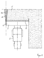
- a sensor unit 1 attached to a combine 2 as a self-propelled harvester is at the front in the direction of travel attached to a cutting unit 3 of the combine 2 on the left.
- the combine 2 has a Reel 4, by means of which the crop 5 in the direction a feed roller 9 is promoted.
- the reel 4 is over a reel support arm 7 pivotally connected.
- a knife 8 is arranged in a lower one.
- Support arm 10 protruding above is arranged at its free end the sensor unit 1 is attached.
- the support arm 10 is with respect to a vertical at an acute angle inclined at the front so that the adjustment of the sensor unit 1 in the direction of a field processing edge 12 facilitated becomes.
- the support arm 10 has such a length that the sensor unit 1 over the reel 4 the field processing edge 12 can detect.
- the sensor unit 1 is in the direction of travel of the combine harvester 2 aligned and has a detection area to be scanned 11 on.
- the sensor unit 1 has a laser sensor as an optical sensor on that is set to a given distance is.
- the previously set distance in an area can be between 12 and 16 m, preferably 14 m, depends on the steering behavior and the driving speed of the combine harvester 2. Is the sensor unit 1 towards one long distance is set, a change in the field processing edge 12 recognized too early, with the effect that the steering of the combine 2 responds too early and thus there is an overload. If the distance is too short has been set, a deviation of the field processing edge 12 recognized too late, so that the steering of the Combine 2 cannot respond in time.
- a prerequisite for correct adjustment is that the combine harvester 2 in the direction of travel and parallel to that provided Field processing edge 12 is arranged.
- the sensor unit 1 can start position on the field processing edge 12 can be adjusted.
- As a reference point for the adjustment of the sensor unit 1 an existing one Field processing edge 12 or edge or a special designated point of the combine harvester 2 itself. At Providing a reference point on the combine 2 is make sure that a corresponding positive guidance is provided which is the sensor unit from the adjustment position spends in the operating position.
- the adjustment device described below is oriented a field processing edge 12.
- the adjustment device enables improved header utilization, because after the sensor unit 1 has been adjusted, the combine harvester 2 automatically with the side edge of the Cutting unit 3 along the detected field processing edge 12 is steered. This is done by the adjustment Cutting with optimal use of the cutting width.
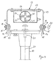
- the sensor unit 1 is on a frame-like u-shaped Attachment 13 attached, which extends downwards opening. Free ends 14 of the projection 13 point coaxially to one another aligned holes 15, in the respective fasteners 16 for screwing to the support arm 10 attached further u-shaped approach 17 can be engaged are.
- the approach 17 of the support arm 10 has upright tabs 18 on, with holes that go to holes 15 of the approach 13 are cursed.
- the approaches 13 and 17 are each on their Ends by the screws 16 with each other connected.
- By loosening a nut 19 at the ends 14 can the sensor unit 1 by a running through the holes 15 Pivot axis 20 can be pivoted. This makes an adjustment allows the sensor unit 1 in a vertical plane.
- the level is the U-shaped extension 17 by means of a screw connection 21 attached to the support arm 10.
- the screw connection 21 extends in the axial direction of the support arm 10 and allows twisting when in a loose position of the U-shaped projection 17 in the circumferential direction of the support arm 10.
- the U-shaped neck 13 of the Sensor unit 1 which screws 16 to the support arm 10 are set, moved.
- the orientation of the sensor unit 1 can be actuated the fastening means 16 on the one hand and the screw connection 21 on the other hand independently in the horizontally and in the vertical direction. This simplifies the adjustment because these adjustment steps are carried out one after the other can be made.
- the display unit 23 has a display field 24 with four rows of display elements 25 with a right angle of two rows of display elements 25 is formed. Each row consists of four display elements 25, each designed as light emitting diodes (LED) are.
- the display elements 25 run on a common one Center point 26, which is a target point for the Adjustment of the sensor unit 1 forms. The adjustment is correct made when each facing the center 26 end display elements 25 light up.
- the display field 24 is designed in the manner of a telescopic sight and therefore self-explanatory for the operator.
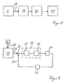
- a sensor signal 28 delivered by the sensor unit 1 is sent to a processing unit while the combine harvester 2 is traveling 29 transferred.
- This is preferably as trained electronic control unit and has a steering program that acts on a steering control unit 30.
- the steering control unit 30 has control valves by means of a steering cylinder 31 is actuated. As shown in Figure 8 can be seen, the sensor signal 28 can thus be used for control purposes of the steering cylinder 31 can be used.
- the sensor signal 28 can also be used to control the Steering cylinder 31 are used, see Figure 9. About this The purpose of this is the sensor signal 28 in the processing unit 29 processed according to a predetermined steering program.
- a target value is located at the output of the processing unit 29 32, which is given to a comparator 33. Find here a comparison with an actual value 34 for the steering angle instead of.
- the so-called control difference is sent to the input given a controller 35, preferably as a digital Regulator is formed.
- the output signal of controller 35 acts on one or more valves 36 that control the steering cylinder 31 taxes.
- the current steering angle of the steering cylinder 31 is detected and by means of a converter 37 which have a transmitter or an analog / digital converter can be transmitted as actual value 34 to the comparison point 33.
- the regulator 35 and the valve 36 form a part a steering control unit 50. It enables the steering cylinder automatically to that of the processing unit 29 predetermined target angle is regulated. This will enables an automatic harvesting journey, with recognition the crop edge by means of the sensor unit 1 the harvesting process reliable and time-saving with optimal utilization the cutting width of the cutting unit 3 performed becomes. By tuning the sensor unit 1 to the left edge of the cutting unit 3 can the crop edge 12 precisely recognized and the crop cut short become.
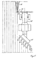
- the sensor unit 1 also for recognizing one by a Furrow formed field edge 38 can be used.
- the Field edge 38 forms the processing edge and can due to different height recognized on both sides of the edge 38 become.
- the sensor unit 1 is on a holding arm 39 mounted on a tractor or agricultural tractor 40, the arm 39 in front of the tractor 40 transversely extends to the direction of travel or to the field edge 38.
- the sensor unit 1 is arranged vertically above the field edge 38 and aligned with this.
- the tractor 40 pulls you Plow 41 after you.
- the display unit 23 is arranged in a driver's cabin and serves to check an automatic adjustment, which, for example, by actuating a Switch can be started by the driver.
- the automatic adjustment takes place through processing and evaluation of the sensor signal generated by the sensor unit 1. This can be done using an electrical cable or wirelessly to the central processing unit 29 of the agricultural tractor 40 are transmitted. In the processing unit 29 becomes the current sensor signal that a particular one Symbolizes the location of the scanned bottom 6, processed. It is necessary that the tractor 40 parallel is positioned to the rim edge 38. After alignment the sensor unit 1 to the field edge 38, the sensor unit 1 or the sensor aligned parallel to the field edge 38 is or has a predetermined zero position the sensor unit 1 assumed the desired adjustment position. The sensor unit 1 can now be fixed in this position become. This adjustment position is determined by a match the lighting up symbolizing the current position of the sensor unit 1 Display element 25 with a predetermined identifier checked. This identifier is preferably in the center 26 of the display unit 23. Depending from the now set position of the sensor unit 1 generates a straight-ahead signal that acts as a reference variable for the automatic steering of the tractor 40 serve can.
- the combine harvester 2 can use one of two ultrasonic sensors 42 formed sensor unit 43 equipped his.
- the sensor unit 43 is on one of front the sensor arm 44 projecting from the cutting unit 3 is movably mounted.
- the sensor support arm 44 is connected to the Cutting unit 3 connected and can be adjusted via a support arm height 45 from an operating position shown in FIG. 6 be pivoted into a lower transport position.
- Those corresponding to the first embodiment Components have the same reference numbers.
- the sensor unit is different from the first exemplary embodiment 43 on a cross arm to the direction of travel 44 hinged bracket 46 attached.
- This arm 46 encompasses the sensor unit 43 with a clip-like one Fastening element 47 that is designed as a clamp and by means of a screw connection 48 on the holding arm 46 is connectable.
- This type of fastening advantageously that the sensor unit 1 quickly in the adjustment position is feasible.
- the sensor unit 43 can aligned simultaneously in the horizontal and vertical directions become.
- the holding arm 46 forms the pivot axis for the orientation in the vertical direction. By moving the sensor unit 43 along the holding arm 46 becomes the alignment the sensor unit 43 causes in the horizontal direction.
- the sensor unit 43 has a first ultrasonic sensor 42, which in the direction of travel along the crop edge 12 is aligned and a second ultrasonic sensor 42 ' on that at an acute angle to the first ultrasonic sensor 42 stands and aligned with the crop 5 itself becomes.
- the ultrasonic sensors 42, 42 ' are inclined in this way trained towards the bottom 6 that their transmission signal in one Distance of more than four meters hits the floor 6. Due to the different orientation of the ultrasonic sensors 42, 42 'can be determined by the ratio of the respective Echo signals the field processing edge 12 are detected.
- the sensor signal thus formed for control or regulation the steering angle of a steering system of the combine harvester 2 be used.
- the adjustment of the ultrasonic sensors 42, 42 ' is carried out by individual display elements 49, which are designed as light-emitting diodes are displayed.
- individual display elements 49 For adjustment in the vertical plane are an upper on a side wall of the sensor unit 43 Display element 49 'and a lower display element 49' 'arranged.
- the sensor unit 43 is too far apart set to floor 6, the upper display element lights up 49 'in red color. Is the sensor unit 43 on one set too close to floor 6, lights up the lower display element 49 '' in red color. Is the sensor unit 43 at a correct distance from the floor 6 the upper and lower display elements light up 49 ', 49' 'in green color.
- a hysteresis circuit integrated so an undesirable Flashing of the display elements 49 ', 49' 'is avoided.
- the sensor unit 43 in the horizontal direction is another display element, not shown provided that when aligning the first ultrasonic sensor 42 lights up on the crop edge 12 in green color.
- the horizontal orientation is only in Exceptional cases required. It can be factory set be made as they depend on the dimensions of the cutting unit 3 must be coordinated. Because the cutting unit 3 forms with its left cutting edge a requirement for the through the same crop edge to be effected 12. It is therefore sufficient usually from that the sensor unit 43 in horizontal Direction is aligned to the cutting unit 3. Thereby, that the second ultrasonic sensor 42 'completely on the crop 5 is directed, can be a unique in a simple manner Sensor signal for the detection of the crop edge 12 generated become. The further processing of the sensor signal can in the first embodiment described above appropriate way.
- the processing unit 29 can be used to Remote control to operate the support arm height adjustment 45.
- Sensor unit 43 can be adjusted in the vertical direction.
- the height is therefore dependent on the crop or Grain height adjustable. It is essential that the sensor set to a certain predetermined distance range becomes.
- the support arm height adjustment 45 is preferred designed as a pressure-actuated cylinder and can be controlled electrically.
- the display unit 23 by one in one Wheelhouse of the combine 2 arranged screen formed be the one with a microprocessor of the processing unit 29 is connected.
- the screen can be beneficial also for other uses, especially for Display of specified steering types, etc. can be used.
Landscapes
- Life Sciences & Earth Sciences (AREA)
- Environmental Sciences (AREA)
- Engineering & Computer Science (AREA)
- Mechanical Engineering (AREA)
- Soil Sciences (AREA)
- Guiding Agricultural Machines (AREA)
- Lifting Devices For Agricultural Implements (AREA)
- Combines (AREA)
- Safety Devices And Accessories For Harvesting Machines (AREA)
Applications Claiming Priority (2)
| Application Number | Priority Date | Filing Date | Title |
|---|---|---|---|
| DE19853085.4A DE19853085B4 (de) | 1998-11-18 | 1998-11-18 | Verfahren zum Justieren einer an einer Feldmaschine befestigten Sensoreinheit sowie eine Justiereinrichtung und eine Feldmaschine |
| DE19853085 | 1998-11-18 |
Publications (2)
| Publication Number | Publication Date |
|---|---|
| EP1002455A2 true EP1002455A2 (fr) | 2000-05-24 |
| EP1002455A3 EP1002455A3 (fr) | 2004-02-11 |
Family
ID=7888145
Family Applications (1)
| Application Number | Title | Priority Date | Filing Date |
|---|---|---|---|
| EP99122102A Ceased EP1002455A3 (fr) | 1998-11-18 | 1999-11-05 | Procédé et dispositif pour ajuster une unité captrice à une machine agricole |
Country Status (6)
| Country | Link |
|---|---|
| US (1) | US6397569B1 (fr) |
| EP (1) | EP1002455A3 (fr) |
| BR (1) | BR9905632A (fr) |
| DE (1) | DE19853085B4 (fr) |
| RU (1) | RU2244399C2 (fr) |
| UA (1) | UA68349C2 (fr) |
Cited By (4)
| Publication number | Priority date | Publication date | Assignee | Title |
|---|---|---|---|---|
| EP1266554A2 (fr) | 2001-06-16 | 2002-12-18 | Deere & Company | Dispositif de direction automatique pour véhicule de travail agricole |
| EP1332659A3 (fr) * | 2002-02-05 | 2004-08-25 | CLAAS Selbstfahrende Erntemaschinen GmbH | Système de localisation pour véhicule de travail agricole automoteur |
| EP2316259A1 (fr) * | 2009-11-03 | 2011-05-04 | CLAAS Selbstfahrende Erntemaschinen GmbH | Dispositif de fixation d'un capteur sans contact de la position relative par rapport à une récolte, notamment une caméra, sur une moissonneuse |
| EP3928606A1 (fr) * | 2020-06-26 | 2021-12-29 | CLAAS E-Systems GmbH | Agencement d'un système de caméra sur une unité de travail agricole |
Families Citing this family (26)
| Publication number | Priority date | Publication date | Assignee | Title |
|---|---|---|---|---|
| US6661524B2 (en) * | 2001-07-09 | 2003-12-09 | United Defense, L.P. | Vehicle regional scanner |
| DE10227484A1 (de) * | 2002-06-19 | 2004-02-26 | Claas Selbstfahrende Erntemaschinen Gmbh | Vorrichtung und Verfahren zur Lagesteuerung eines Erntegutaufnahmegerätes landwirtschaftlicher Erntemaschinen |
| CA2427416C (fr) * | 2003-05-01 | 2010-11-16 | 101039130 Saskatchewan Ltd. | Dispositif de direction pour outils remorques |
| DE10342922A1 (de) * | 2003-09-15 | 2005-05-19 | Claas Selbstfahrende Erntemaschinen Gmbh | Häcksel- und Verteilvorrichtung |
| US7916898B2 (en) * | 2003-09-15 | 2011-03-29 | Deere & Company | Method and system for identifying an edge of a crop |
| US7412905B1 (en) | 2004-05-31 | 2008-08-19 | Richard Anthony Bishel | Paddle sensor |
| US7349779B2 (en) * | 2004-12-21 | 2008-03-25 | Deere & Company | Automatic steering system |
| RU2332824C1 (ru) * | 2007-03-22 | 2008-09-10 | Российская академия Сельскохозяйственных наук Государственное научное учреждение Всероссийский научно-исследовательский институт электрификации сельского хозяйства (ГНУ ВИЭСХ) | Система управления движением мобильного подвижного сельскохозяйственного объекта |
| DE202007014710U1 (de) * | 2007-10-18 | 2008-11-27 | Bucyrus Dbt Europe Gmbh | Gewinnungseinrichtung für die Mineraliengewinnung und Aufnahmeeinrichtung für ein Sensorsystem hierfür |
| RU2465410C1 (ru) * | 2011-05-03 | 2012-10-27 | Государственное образовательное учреждение высшего профессионального образования "Сибирская государственная автомобильно-дорожная академия (СибАДИ)" | Устройство для определения положения рабочего органа дорожно-строительной машины с помощью спутниковых систем навигации gps/глонасс или световых, например лазерных, излучателей |
| US9051127B2 (en) * | 2012-04-03 | 2015-06-09 | Scott Conroy | Grain auger protection system |
| US8781685B2 (en) * | 2012-07-17 | 2014-07-15 | Agjunction Llc | System and method for integrating automatic electrical steering with GNSS guidance |
| US9585309B2 (en) * | 2015-07-14 | 2017-03-07 | Cnh Industrial America Llc | Header height control system for an agricultural harvester |
| US11219160B2 (en) * | 2018-12-18 | 2022-01-11 | Kubota Corporation | Riding mower with a cutting guide |
| US11383728B2 (en) | 2019-03-14 | 2022-07-12 | Cnh Industrial America Llc | System and method for collecting data associated with the operation of an agricultural machine in different operating modes |
| US11202410B2 (en) * | 2019-04-30 | 2021-12-21 | Deere & Company | Light-emitting mechanism on crop divider rod of harvesting header |
| US11369052B2 (en) | 2019-08-15 | 2022-06-28 | Cnh Industrial America Llc | System and method for monitoring plugging of basket assemblies of an agricultural implement |
| US12137630B2 (en) | 2019-12-23 | 2024-11-12 | Cnh Industrial America Llc | Sensor assembly for an agricultural header |
| US12520764B2 (en) | 2019-12-23 | 2026-01-13 | Cnh Industrial America Llc | Reel assembly with retractable sensor arm for an agricultural header |
| US11533851B2 (en) | 2019-12-23 | 2022-12-27 | Cnh Industrial America Llc | Reel assembly for an agricultural header |
| AR120844A1 (es) | 2019-12-23 | 2022-03-23 | Cnh Ind America Llc | Conjunto de molinete para un cabezal agrícola |
| US20220400606A1 (en) * | 2021-06-18 | 2022-12-22 | Green Industry Innovators, L.L.C. | Landscaping equipment with included laser and methods of operation |
| EP4391790A1 (fr) * | 2021-08-23 | 2024-07-03 | CNH Industrial Belgium NV | Système de support de capteur pour un outil de récolte d'une moissonneuse agricole |
| US20240180055A1 (en) * | 2022-12-01 | 2024-06-06 | Cnh Industrial America Llc | Sensor support assembly for an agricultural implement |
| US20250000025A1 (en) * | 2023-06-30 | 2025-01-02 | Cnh Industrial America Llc | Rotary actuator system for work vehicle |
| US12560560B2 (en) | 2023-08-11 | 2026-02-24 | Cnh Industrial America Llc | Agricultural system and method for monitoring plugging of ground-engaging tools of an agricultural implement |
Citations (1)
| Publication number | Priority date | Publication date | Assignee | Title |
|---|---|---|---|---|
| US3991618A (en) | 1973-12-18 | 1976-11-16 | Maschinenfabrik Fahr Aktiengesellschaft | Sensor for automatic steering system for row-crop harvester |
Family Cites Families (33)
| Publication number | Priority date | Publication date | Assignee | Title |
|---|---|---|---|---|
| BE757894A (nl) * | 1970-10-23 | 1971-04-01 | Clayson Nv | Inrichting voor de automatische besturing van landbouwmachines meer speciaal maaidorsers, (uitv. : g. strubbe), |
| FR2240678B1 (fr) * | 1973-08-14 | 1978-01-13 | Fahr Ag Maschf | |
| FR2254265A2 (en) * | 1973-08-14 | 1975-07-11 | Fahr Ag Maschf | Combine harvester automatic guidance system - has sensor head near rear steering wheel, pickups, travel stops, and program changeover |
| DE2555283C3 (de) * | 1975-12-09 | 1980-12-18 | Maschinenfabrik Fahr Ag Gottmadingen, 7702 Gottmadingen | Anordnung zur selbsttätigen Lenkung eines landwirtschaftlich genutzten Fahrzeuges |
| US4219093A (en) * | 1978-08-04 | 1980-08-26 | Zahnradfabrik Friedrichshafen Ag | Vehicle steering assist |
| US4263979A (en) | 1978-11-09 | 1981-04-28 | Rpc Corporation | Hydraulic master-slave steering system for a wide track vehicle |
| NZ195877A (en) * | 1980-01-10 | 1984-07-31 | Massey Ferguson Services Nv | Crop collecting table or platform for combine harvester and height control thereof |
| US4561797A (en) * | 1983-09-26 | 1985-12-31 | Aldridge Byron D | Universal clevis |
| US4641986A (en) * | 1985-08-30 | 1987-02-10 | Cbc Industries, Inc. | Multi-position eyebolt |
| JPS6434202A (en) * | 1987-07-30 | 1989-02-03 | Kubota Ltd | Working wagon of automatic conduct type |
| US4967362A (en) * | 1989-01-30 | 1990-10-30 | Eaton Corporation | Automatic steering apparatus for crop vehicle |
| US5002420A (en) * | 1989-06-09 | 1991-03-26 | Aeroquip Corporation | Swivel snap hook |
| DE4004247A1 (de) * | 1990-02-12 | 1991-08-14 | Feser Werner | Servo-geregeltes bearbeitungs-grundgeraet mit elektronischer pflanzenabtastung |
| US5303636A (en) | 1990-04-23 | 1994-04-19 | Eaton Corporation | Fluid controller and logic control system for use therewith |
| AU653958B2 (en) * | 1990-09-24 | 1994-10-20 | Andre Colens | Continuous, self-contained mowing system |
| US5234070A (en) * | 1991-02-25 | 1993-08-10 | Trw Inc. | Automatic vehicle steering apparatus |
| DE9207482U1 (de) * | 1992-06-03 | 1992-08-20 | Wilhelm Stoll Maschinenfabrik Gmbh, 3325 Lengede | Landwirtschaftliche Maschine, insbesondere Rübenerntemaschine |
| DE9312542U1 (de) * | 1992-11-24 | 1993-10-07 | Manz, Werner, 88212 Ravensburg | Automatisch selbstfahrende Arbeitsmaschine zur Bearbeitung von definierten Flächen |
| US5393162A (en) * | 1993-02-24 | 1995-02-28 | Nissen; Carl-Erik M. | Pivoting joint assembly |
| DE4339600A1 (de) * | 1993-11-20 | 1995-05-24 | Kloeckner Humboldt Deutz Ag | Land- oder bauwirtschaftliches Fahrzeug, das optisch überwacht wird und fernsteuerbar ist |
| US5528888A (en) * | 1993-12-27 | 1996-06-25 | Fuji Jukogyo Kabushiki Kaisha | Autonomous mowing vehicle and apparatus for detecting boundary of mowed field |
| DE4419421C2 (de) * | 1994-06-03 | 1996-03-28 | Claas Ohg | Verteilvorrichtung für Häcksler |
| DE19508941A1 (de) * | 1995-03-13 | 1996-09-19 | Claas Ohg | Ortungsvorrichtung |
| DE19508942A1 (de) | 1995-03-13 | 1996-09-19 | Claas Ohg | Reflex-Ortungsvorrichtung |
| DE19508944A1 (de) * | 1995-03-13 | 1996-09-19 | Claas Ohg | Selbstlenkvorrichtung |
| GB9519565D0 (en) * | 1995-09-26 | 1995-11-29 | Ford New Holland Nv | Apparatus for controlling a position-adjustable implement |
| DE19539275A1 (de) * | 1995-10-21 | 1997-04-24 | Baumann Hans Dr | EDV-Stativ |
| EP0801885B1 (fr) * | 1996-04-19 | 2002-01-09 | Carnegie-Mellon University | Guidage par rapport à ligne de récolte basé sur la vision |
| US5782072A (en) * | 1996-07-11 | 1998-07-21 | Matthews; H. Wayne | Crop tracking row units on cotton harvesters |
| DE19703836C2 (de) | 1997-02-01 | 1999-09-09 | Bertsch | Elektromagnetisches Einspritzventil für Brennkraftmaschinen |
| DE19716201B4 (de) * | 1997-04-18 | 2012-11-15 | Claas Kgaa Mbh | Mehrachslenkung |
| DE19719939A1 (de) * | 1997-05-13 | 1998-11-19 | Claas Ohg | Automatisch lenkbare Erntemaschine |
| DE19743884C2 (de) * | 1997-10-04 | 2003-10-09 | Claas Selbstfahr Erntemasch | Vorrichtung und Verfahren zur berührungslosen Erkennung von Bearbeitungsgrenzen oder entsprechenden Leitgrößen |
-
1998
- 1998-11-18 DE DE19853085.4A patent/DE19853085B4/de not_active Expired - Fee Related
-
1999
- 1999-11-05 EP EP99122102A patent/EP1002455A3/fr not_active Ceased
- 1999-11-16 RU RU99124419/11A patent/RU2244399C2/ru not_active IP Right Cessation
- 1999-11-17 US US09/442,433 patent/US6397569B1/en not_active Expired - Fee Related
- 1999-11-17 UA UA99116264A patent/UA68349C2/uk unknown
- 1999-11-17 BR BR9905632-1A patent/BR9905632A/pt not_active IP Right Cessation
Patent Citations (1)
| Publication number | Priority date | Publication date | Assignee | Title |
|---|---|---|---|---|
| US3991618A (en) | 1973-12-18 | 1976-11-16 | Maschinenfabrik Fahr Aktiengesellschaft | Sensor for automatic steering system for row-crop harvester |
Cited By (6)
| Publication number | Priority date | Publication date | Assignee | Title |
|---|---|---|---|---|
| EP1266554A2 (fr) | 2001-06-16 | 2002-12-18 | Deere & Company | Dispositif de direction automatique pour véhicule de travail agricole |
| EP1266554A3 (fr) * | 2001-06-16 | 2004-07-21 | Deere & Company | Dispositif de direction automatique pour véhicule de travail agricole |
| US7350343B2 (en) | 2001-06-16 | 2008-04-01 | Deere & Company | System for automatically steering a utility vehicle |
| EP1332659A3 (fr) * | 2002-02-05 | 2004-08-25 | CLAAS Selbstfahrende Erntemaschinen GmbH | Système de localisation pour véhicule de travail agricole automoteur |
| EP2316259A1 (fr) * | 2009-11-03 | 2011-05-04 | CLAAS Selbstfahrende Erntemaschinen GmbH | Dispositif de fixation d'un capteur sans contact de la position relative par rapport à une récolte, notamment une caméra, sur une moissonneuse |
| EP3928606A1 (fr) * | 2020-06-26 | 2021-12-29 | CLAAS E-Systems GmbH | Agencement d'un système de caméra sur une unité de travail agricole |
Also Published As
| Publication number | Publication date |
|---|---|
| RU2244399C2 (ru) | 2005-01-20 |
| US6397569B1 (en) | 2002-06-04 |
| EP1002455A3 (fr) | 2004-02-11 |
| UA68349C2 (uk) | 2004-08-16 |
| DE19853085B4 (de) | 2014-03-20 |
| BR9905632A (pt) | 2000-10-17 |
| DE19853085A1 (de) | 2000-05-25 |
Similar Documents
| Publication | Publication Date | Title |
|---|---|---|
| DE19853085B4 (de) | Verfahren zum Justieren einer an einer Feldmaschine befestigten Sensoreinheit sowie eine Justiereinrichtung und eine Feldmaschine | |
| EP1408732B1 (fr) | Dispositif de distribution con u pour des produits haches issus d'une recolteuse | |
| EP3259976B1 (fr) | Engin agricole et procédé de fonctionnement d'un engin agricole | |
| DD226747A5 (de) | Reihenabtastvorrichtung fuer eine erntemaschine | |
| EP3300561B1 (fr) | Machine agricole automotrice | |
| EP1219159A1 (fr) | Procédé et dispositif de commande automatique d'un appareil de transfert de machines agricoles de récolte | |
| DE19509496A1 (de) | Selbstfahrender Mähdrescher | |
| DE102017110637B4 (de) | Vollautomatischer Zinkenstriegel | |
| EP1151652A1 (fr) | Récolteuse en particulier faucheuse-hacheuse | |
| DE102004059543A1 (de) | Landwirtschaftliche Arbeitsmaschine | |
| DE102009047181B4 (de) | Landwirtschaftliches Bodenbearbeitungsgerät zur Befestigung an einem Fahrzeug | |
| EP3772265A1 (fr) | Dispositif de houe | |
| EP3783529A1 (fr) | Système de sécurité et procédé de fonctionnement d'une machine de travail agricole mobile | |
| EP3138733A1 (fr) | Systeme de controle d'un dispositif d'eclairage d'un vehicule de travail | |
| EP0518171A1 (fr) | Moyen d'ajustage de la profondeur, réglable verticalement, avec un patin | |
| EP0992185B1 (fr) | Système automatique de direction à localisation ultrasonore | |
| EP0713639A1 (fr) | Dispositif palpeur pour le guidage latéral automatique d'un moissonneuse automotrice | |
| EP1733606A1 (fr) | Procédé et dispositif pour faire fonctionner un attachement pour la récolte de plantes à tiges | |
| DE69305257T2 (de) | Navigationsverfahren und -vorrichtung für ein automatisch geführtes Fahrzeug | |
| EP0818136B1 (fr) | Dispositif pour hacher des végétaux | |
| EP3791707A1 (fr) | Dispositif de traitement au sol de matériau végétal et procédé de traitement au sol de matériau végétal | |
| EP3613273A1 (fr) | Moissonneuse-batteuse | |
| EP3298878A1 (fr) | Dispositif pour la récolte de baies | |
| EP1862049A1 (fr) | Machine agricole | |
| DE29919023U1 (de) | Schwadeinrichtung mit Zusatzband |
Legal Events
| Date | Code | Title | Description |
|---|---|---|---|
| PUAI | Public reference made under article 153(3) epc to a published international application that has entered the european phase |
Free format text: ORIGINAL CODE: 0009012 |
|
| AK | Designated contracting states |
Kind code of ref document: A2 Designated state(s): AT BE CH CY DE DK ES FI FR GB GR IE IT LI LU MC NL PT SE |
|
| AX | Request for extension of the european patent |
Free format text: AL;LT;LV;MK;RO;SI |
|
| PUAL | Search report despatched |
Free format text: ORIGINAL CODE: 0009013 |
|
| AK | Designated contracting states |
Kind code of ref document: A3 Designated state(s): AT BE CH CY DE DK ES FI FR GB GR IE IT LI LU MC NL PT SE |
|
| AX | Request for extension of the european patent |
Extension state: AL LT LV MK RO SI |
|
| RIC1 | Information provided on ipc code assigned before grant |
Ipc: 7A 01D 41/12 B Ipc: 7A 01B 69/00 A |
|
| 17P | Request for examination filed |
Effective date: 20040811 |
|
| AKX | Designation fees paid |
Designated state(s): AT BE CH CY DE DK ES FI FR GB GR IE IT LI LU MC NL PT SE |
|
| 17Q | First examination report despatched |
Effective date: 20050914 |
|
| RAP1 | Party data changed (applicant data changed or rights of an application transferred) |
Owner name: CLAAS SELBSTFAHRENDE ERNTEMASCHINEN GMBH |
|
| STAA | Information on the status of an ep patent application or granted ep patent |
Free format text: STATUS: THE APPLICATION HAS BEEN REFUSED |
|
| 18R | Application refused |
Effective date: 20160331 |