EP1002497A2 - Système d'imagerie de vaisseau sanguin - Google Patents
Système d'imagerie de vaisseau sanguin Download PDFInfo
- Publication number
- EP1002497A2 EP1002497A2 EP99123025A EP99123025A EP1002497A2 EP 1002497 A2 EP1002497 A2 EP 1002497A2 EP 99123025 A EP99123025 A EP 99123025A EP 99123025 A EP99123025 A EP 99123025A EP 1002497 A2 EP1002497 A2 EP 1002497A2
- Authority
- EP
- European Patent Office
- Prior art keywords
- organism
- light beam
- components
- frequency
- measuring light
- Prior art date
- Legal status (The legal status is an assumption and is not a legal conclusion. Google has not performed a legal analysis and makes no representation as to the accuracy of the status listed.)
- Granted
Links
Images






Classifications
-
- A—HUMAN NECESSITIES
- A61—MEDICAL OR VETERINARY SCIENCE; HYGIENE
- A61B—DIAGNOSIS; SURGERY; IDENTIFICATION
- A61B5/00—Measuring for diagnostic purposes; Identification of persons
- A61B5/02—Detecting, measuring or recording for evaluating the cardiovascular system, e.g. pulse, heart rate, blood pressure or blood flow
- A61B5/026—Measuring blood flow
- A61B5/0261—Measuring blood flow using optical means, e.g. infrared light
Definitions
- Another object of the present invention is to provide a blood vessel distinguishing system which can clearly distinguish arteries and veins from each other without exposing the testee to heavy load.
- the in-phase time detecting means may be, for instance, a means for detecting the pulse wave of the organism, or a means for detecting the times at which the center frequency component of the beat component detection signal takes a predetermined peak value.
- the measuring light source comprises a linear or two-dimensional array of a plurality of light emitting portions and the optical heterodyne detection system is arranged to be able to detect in parallel beat components of the combined light beams based on the measuring light beams from the respective light emitting portions, and the measuring light source and the optical heterodyne detection system also function as at least a part of said scanning means.
- beat component detection signal (beat signal) output from the heterodyne detection system described above represents intensity of only straight light components traveling straight through the organism or scattered light components close to the straight light components except influence of scattering by the organism which is a scattering medium.
- blood is also a fluid which causes multiple scattering of light
- the same phenomenon occurs when the measuring light beam passes through a blood vessel. Since arterial blood is generally higher than venous blood in flow rate, the reduction in the peak value of the intensity of the beat signal and broadening of the spectrum are larger when the measuring light beam travels through an artery than when the measuring light beam travels through a vein.
- a measuring light source comprising a linear or two-dimensional array of a plurality of light emitting portions and an optical heterodyne detection system which can detect in parallel beat components of the combined light beams based on the measuring light beams from the respective light emitting portions
- the measuring light source and the optical heterodyne detection system also function as at least a part of said scanning means, it becomes unnecessary for the scanning means to mechanically cause the measuring light beam to scan the organism in at least one direction, whereby the scanning speed, which results in the imaging speed, can be increased.
- This is especially advantageous in the case where the off-centered beat signal is sampled at said in-phase times and sampling of the off-centered beat signal requires a relatively long time.
- a blood vessel imaging system comprising
- a blood vessel imaging system comprising
- the beat component detection signal (beat signal) output from the heterodyne detection system described above represents intensity of only straight light components traveling straight through the organism or scattered light components close to the straight light components except influence of scattering by the organism which is a scattering medium.
- Figure 11A shows a spectrum of the beat signal when the flow rate of the fluid is 0, and Figures 11B to 11D show those for different flow rates of the fluid which increase in this order.
- the peak value of the intensity of the beat signal becomes lower and the spectrum of the beat signal is broadened (Doppler broadening) as the flow rate of the fluid increases.
- the ratio I( ⁇ + ⁇ f)/ I( ⁇ ) , to the intensity I( ⁇ ) of the center frequency components of the beat signal (the components of the beat signal at the center frequency ⁇ ), of the intensity I( ⁇ + ⁇ f) of the off-centered components of the beat signal in a frequency band deviated from the center frequency ⁇ by a predetermined width changes with the flow rate v of the fluid substantially as shown in Figure 12.
- the same phenomenon occurs when the measuring light beam passes through a blood vessel. Since arterial blood is generally higher than venous blood in flow rate, the ratio I( ⁇ + ⁇ f)/I( ⁇ ) is larger when the measuring light beam travels through an artery than when the measuring light beam travels through a vein.
- the intensity ratio that is, the value obtained by normalizing the intensity I( ⁇ + ⁇ f) of the off-centered components of the beat signal by the intensity I( ⁇ ) of the center frequency components of the beat signal, changes basically depending solely on the flow rate of blood in the manner described above with the influence of the attenuation compensated for.
- the image signal generating means when the image signal generating means generates an image signal on the basis of the intensity ratio I( ⁇ + ⁇ f)/ I( ⁇ ) , for instance, so that the image signal takes a higher value as the intensity increases, the artery parts and the vein pads can be imaged to be clearly distinguishable from each other from density and/or brightness.
- the artery parts and the vein parts can be imaged to be clearly distinguishable from each other also by generating an image signal on the basis of the spectral waveform of the beat signal in place of the intensity ratio I( ⁇ + ⁇ f)/ I( ⁇ ) as in the blood vessel imaging system of the third aspect.
- the image signal is generated on the basis of a spectral width between two frequencies at which the intensity of the beat component detection signal takes a predetermined value with respect to the intensity of the center frequency components, for instance, a half-width of the spectrum. Since such a spectral width becomes larger as the flow rate of blood increases as can be seen from Figures 11A to 11D, the artery parts and the vein parts can be imaged to be clearly distinguishable from each other from density and/or brightness when the image signal is generated, for instance, so that the image signal takes a higher value as the spectral width becomes larger.
- the artery parts and the vein parts can be accurately distinguished from each other on the basis of the spectral width.
- the imaging means may be a means which detects frequency components of the measuring light scattered by the organism, detects the intensity of off-centered components in a frequency band deviated from the center frequency of the frequency detection signal by a predetermined width and images an artery and/or a vein in the organism on the basis of the intensity.
- the imaging means may be a means which detects frequency components of the measuring light scattered by the organism, detects the ratio between the intensity of center frequency components of the frequency detection signal and the intensity of off-centered components in a frequency band deviated from the center frequency of the frequency detection signal by a predetermined width and images an artery and/or a vein in the organism on the basis of the intensity ratio.
- the imaging means may be a means which detects frequency components of the measuring light scattered by the organism on the basis of an optical heterodyne detection signal.
- a blood vessel distinguishing system comprising
- the distinguishing means detects frequency components of the measuring light scattered by the organism, detects the half-width of the spectrum of the frequency detection signal and distinguishes an artery and a vein in the organism from each other on the basis of the half-width.
- the distinguishing means may be a means which detects frequency components of the measuring light scattered by the organism, detects the intensity of off-centered components in a frequency band deviated from the center frequency of the frequency detection signal by a predetermined width and distinguishes an artery and a vein in the organism from each other on the basis of the intensity.
- the distinguishing means may be a means which detects frequency components of the measuring light scattered by the organism on the basis of an optical heterodyne detection signal.
- a flow rate measuring system for measuring a flow rate of light scattering fluid comprising
- the analysis means analyzes frequency components of the measuring light scattered by the organism, detects the half-width of the spectrum of the frequency detection signal and analyzes the flow rate of the light scattering fluid on the basis of the half-width.
- the analysis means may be a means which detects frequency components of the measuring light scattered by the organism, detects the intensity of off-centered components in a frequency band deviated from the center frequency of the frequency detection signal by a predetermined width and analyzes the flow rate of the light scattering fluid on the basis of the intensity.
- the analysis means may be a means which detects frequency components of the measuring light scattered by the organism, detects the ratio between the intensity of center frequency components of the frequency detection signal and the intensity of off-centered components in a frequency band deviated from the center frequency of the frequency detection signal by a predetermined width and analyzes the flow rate of the light scattering fluid on the basis of the intensity ratio.
- the analysis means may be a means which detects frequency components of the measuring light scattered by the organism on the basis of an optical heterodyne detection signal.
- an artery and/or a vein is imaged on the basis of broadening of the spectrum due to an interaction of the measuring light with the organism, the artery and/or the vein can be imaged as in the preceding blood vessel imaging systems, where an optical heterodyne detection system is employed.
- the imaging system further comprises a personal computer (PC) 20 which receives output of the level meter 15 and forms an image signal generating means together with the level meter 15, and an image monitor 21 such as a CRT display connected to the personal computer 20.
- PC personal computer
- a X-Y stage 23 which is movable in X and Y directions supporting thereon an object (e.g., a human finger) 22.
- a stage driver 24 drives the X-Y stage 23 under the control of the personal computer 20.
- the optical system 12 and the photodetector 13 form an optical heterodyne detection system.
- the optical system 12 comprises a first half-silvered mirror 30 which splits the measuring light beam L into a first light beam L1 (the part of the measuring light beam L reflected by the first half-silvered mirror 30) and a second light beam L2 (the part of the measuring light beam L passing through the first half-silvered mirror 30), a first mirror 31 which reflects the first light beam L1 to impinge upon the object 22, a second mirror 32 which reflects the second light beam L2, a second half-silvered mirror 33 which combines the first light beam L1 passing through the object 22 with the second light beam L2 reflected from the second mirror 32 into a combined light beam Lc, and a third mirror 35 which reflects the combined light beam Lc to impinge upon the photodetector 13.
- a frequency shifter 34 provided on the optical path of the second light beam L2 shifts the second light beam L2 by a predetermined amount so that the center frequency of the second light beam L2 becomes ⁇ .
- the frequency shifter 34 may comprise, for instance, an AOM.
- a measuring light beam L is emitted from the laser 11 and the first light beam L1 is projected onto the object 22.
- the X-Y stage 23 is moved in X and Y directions, whereby the first light beam L1 is caused to two-dimensionally scan the object 22.
- the combined light beam Lc includes therein beat components whose center frequency is ⁇ , equal to that of the frequency-shifted second light beam L2.
- the output of the photodetector 13 upon receipt of the combined light beam Lc includes a beat signal B generated by the beat components.
- the output of the photodetector 13 is input into the band-pass filter 14.
- the beat signal B represents intensity of only straight light components traveling straight through the object 22, which is a scattering medium, or scattered light components close to the straight light components. Accordingly, by obtaining an image signal for the object 22 on the basis of the beat signal B, a high spatial resolution can be ensured though the measuring light beam L (the first light beam L1) is scattered by the object 22.
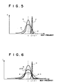
- the band-pass filter 14 selectively transmits signal components in a frequency band near the frequency ( ⁇ + ⁇ f) deviated from the center frequency ⁇ of the beat signal B by a predetermined width ⁇ f as shown by line c in Figure 5.
- the signal passing through the band-pass filter 14, that is, off-centered beat signal Bo is input into the level meter 15.
- the level meter 15 measures a level of the off-centered beat signal Bo at a predetermined timing, e.g., at a time at which the off-centered beat signal Bo takes a peak value, and inputs a level signal SL representing the measured level of the off-centered beat signal Bo into the personal computer 20.
- the personal computer 20 compares the level of the off-centered beat signal Bo represented by the level signal SL with a predetermined threshold level such as represented by d in Figure 5.
- a predetermined threshold level such as represented by d in Figure 5.
- the personal computer 20 When an artery is to be imaged, the personal computer 20 generates an image signal component Sp bearing thereon a relatively high density (low brightness) when the level of the off-centered beat signal Bo is higher than the threshold level and otherwise an image signal component Sp bearing thereon a relatively low density (high brightness), and inputs the image signal component Sp into the monitor 21.
- the level meter 15 outputs an off-centered beat signal Bo for each scanning spot on the object 22 as the first light beam L1 scans the object 22. Accordingly, the two-valued image signal component Sp is generated for each scanning spot on the object 22.
- the image monitor 21 reproduces a two-dimensional image on the basis of an image signal made up of the image signal components Sp thus generated for the respective scanning spots.
- the artery part is shown as a relatively high density part on a background at a relatively low density.
- the personal computer 20 when a vein is to be imaged, the personal computer 20 generates an image signal component Sp bearing thereon a relatively high density (low brightness) when the level of the off-centered beat signal Bo is lower than the threshold level and otherwise an image signal component Sp bearing thereon a relatively low density (high brightness), and inputs the image signal component Sp into the monitor 21.
- the image monitor 21 reproduces a two-dimensional image on the basis of an image signal made up of the image signal components Sp thus generated for the respective scanning spots.
- the vein part is shown as a relatively high density part on a background at a relatively low density.
- a blood vessel imaging system in accordance with a second embodiment of the present invention will be described with reference to Figure 2, hereinbelow.
- the blood vessel imaging system of this embodiment basically differs from that of the first embodiment in that there are provided a pulsation signal detecting means 50 which detects a pulsation wave of the object 22, and a synchronization detecting means 51 which samples the level signal SL on the basis of a pulsation signal Sc output from the pulsation signal detecting means 50.
- the synchronization detecting means 51 samples the level signal SL at times at which broadening of the spectrum of the beat signal B becomes of a predetermined phase (in this particular embodiment, times at which the flow rate of the arterial blood is maximized), and inputs the sampled level signal SL into the personal computer 20.
- the level of the off-centered beat signal Bo can be detected when broadening of the spectrum of the beat signal B is in a state shown by line a-1 in Figure 6 far from a state shown by line b representing broadening of the spectrum of the beat signal B when the measuring light beam L travels through a vein, whereby the artery part and the vein part can be imaged clearly distinguished from each other.
- a blood vessel imaging system in accordance with a third embodiment of the present invention will be described with reference to Figure 3, hereinbelow.
- the blood vessel imaging system of this embodiment basically differs from that of the second embodiment in that there are provided, in place of the pulsation signal detecting means 50, a second photodetector 63 which receives the combined light beam Lc, a second band-pass filter 64 which is connected to the photodetector 63 and transmits only a signal in a predetermined frequency band to be described later, and a second level meter 65 which is connected to the band-pass filter 64.
- the second band-pass filter 64 selectively transmits signal components in a frequency band near the center frequency ⁇ of the beat signal B included in the output of the second photodetector 63.
- the signal B ⁇ passing through the second band-pass filter 64 is input into the second level meter 65.
- the second level meter 65 outputs a timing signal St when the peak level of the signal B ⁇ falls below a preset value and inputs it into the synchronization detecting means 51.
- the synchronization detecting means 51 samples the level signal SL upon receipt of the timing signal St, and inputs the sampled level signal SL into the personal computer 20.
- the synchronization detecting means 51 can sample the level signal SL at times at which broadening of the spectrum of the beat signal B becomes of a predetermined phase (in this particular embodiment, times at which the flow rate of the arterial blood is maximized). Accordingly, the level of the off-centered beat signal Bo can be detected when broadening of the spectrum of the beat signal B is in a state shown by line a-1 in Figure 6 far from a state shown by line b representing broadening of the spectrum of the beat signal B when the measuring light beam L travels through a vein, whereby the artery part and the vein part can be imaged clearly distinguished from each other.
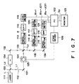
- a blood vessel imaging system in accordance with a fourth embodiment of the present invention comprises a laser 111 emitting a measuring light beam L at a wavelength of ⁇ , an optical heterodyne optical system 112, first to third photodetectors 113 to 115 which receive the measuring light beam L emanating from the optical heterodyne optical system 112, first to third band-pass filters (BPF) 116 to 118 which are respectively connected to the photodetectors 113 to 115 and selectively transmit signals in predetermined frequency bands to be described later, and first to third level meters 119 to 121 respectively connected to the band-pass filters 116 to 118.
- BPF band-pass filters
- the imaging system further comprises a personal computer (PC) 222 which receives outputs of the level meters 119 to 121 and forms an image signal generating means together with the level meters 119 to 121, and an image monitor 123 such as a CRT display connected to the personal computer 122.
- PC personal computer
- a X-Y stage 125 which is movable in X and Y directions supporting thereon an object (e.g., a human finger) 124.
- a stage driver 126 drives the X-Y stage 125 under the control of the personal computer 122.
- the optical system 112 and the photodetectors 113 to 115 form an optical heterodyne detection system.
- the optical system 112 comprises a first half-silvered mirror 130 which splits the measuring light beam L into a first light beam L1 (the part of the measuring light beam L reflected by the first half-silvered mirror 130) and a second light beam L2 (the part of the measuring light beam L passing through the first half-silvered mirror 130), a first mirror 131 which reflects the first light beam L1 to impinge upon the object 124, a second mirror 132 which reflects the second light beam L2, and a second half-silvered mirror 133 which combines the first light beam L1 passing through the object 124 with the second light beam L2 reflected from the second mirror 132 into a combined light beam Lc and causes the combined light beam Lc to partly impinge upon the first photodetector 113 and partly impinge upon a third half-silvered mirror 135.
- the optical system 112 further comprises the third half-silvered mirror 135 and a third mirror 136 which reflects the part of the combined light beam Lc passing through the third half-silvered mirror 135 to impinge upon the third photodetector 115.
- the third half-silvered mirror 135 reflects a part of the combined light beam Lc to impinge upon the second photodetector 114 and transmits the other part of the combined light beam Lc.
- a measuring light beam L is emitted from the laser 111 and the first light beam L1 is projected onto the object 124. While projecting the first light beam L1, the X-Y stage 125 is moved in X and Y directions, whereby the first light beam L1 is caused to two-dimensionally scan the object 124.
- each of the combined light beams Lc includes therein beat components whose center frequency is ⁇ , equal to that of the frequency-shifted second light beam L2.
- the outputs of the photodetectors 113 to 115 upon receipt of the combined light beam Lc include a beat signal B generated by the beat components.
- the outputs of the photodetectors 113 to 115 are respectively input into the band-pass filters 116 to 118.
- the beat signal B represents intensity of only straight light components traveling straight through the object 124, which is a scattering medium, or scattered light components close to the straight light components. Accordingly, by obtaining an image signal for the object 124 on the basis of the beat signal B, a high spatial resolution can be ensured though the measuring light beam L (the first light beam L1) is scattered by the object 124.
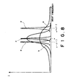
- the band-pass filter 116 selectively transmits signal components in a frequency band near the center frequency ⁇ of the beat signal B as shown by line c in Figure 8.
- the band-pass filter 117 selectively transmits signal components in a frequency band near the frequency ( ⁇ + ⁇ f2) deviated from the center frequency ⁇ of the beat signal B toward the higher frequency side by a predetermined width ⁇ f2 as shown by line d in Figure 8.
- the band-pass filter 118 selectively transmits signal components in a frequency band near the frequency ( ⁇ - ⁇ f3) deviated from the center frequency ⁇ of the beat signal B toward the lower frequency side by a predetermined width ⁇ f3 as shown by line e in Figure 8.
- the widths ⁇ f2 and ⁇ f3 are set so that the former is larger than the latter, that is, ⁇ f2> ⁇ f3 .
- the outputs of the band-pass filters 116 to 118 are respectively input into the level meters 119 to 121.
- the level meters 119 to 121 measure levels of the input signals at a predetermined timing, e.g., at a time at which the signal levels are maximized, and input signals representing the measured levels of the signals B( ⁇ ), B( ⁇ + ⁇ f2) and B( ⁇ - ⁇ f3) into the personal computer 122.
- the personal computer 20 calculates an intensity ratio I( ⁇ + ⁇ f2)/I( ⁇ ) when an artery is to be imaged, and generates an image signal component Sp which bears thereon a higher density (lower brightness) as the intensity ratio increase, and inputs the image signal component Sp into the monitor 123.
- the image monitor 123 reproduces a two-dimensional image on the basis of an image signal made up of the image signal components Sp thus generated for the respective scanning spots.
- the artery part is shown as a relatively high density part.
- the personal computer 20 calculates an intensity ratio I( ⁇ - ⁇ f3)/I( ⁇ ) , and generates an image signal component Sp which bears thereon a higher density (lower brightness) as the intensity ratio decreases, and inputs the image signal component Sp into the monitor 123.
- the image monitor 123 reproduces a two-dimensional image on the basis of an image signal made up of the image signal components Sp thus generated for the respective scanning spots.
- the vein part is shown as a relatively high density part.
- the image signal component Sp is generated so that the image signal components bears thereon a higher density as the intensity ratio I( ⁇ + ⁇ f2)/I( ⁇ ) increases when an artery image is to be displayed, and the image signal components bears thereon a higher density as the intensity ratio I( ⁇ + ⁇ f2)/I( ⁇ ) decreases when a vein image is to be displayed.
- the image signal component Sp is generated in the manner described above, it becomes unnecessary to generate an image signal component Sp representing a vein image on the basis of an extremely small value (close to 0) of the intensity ratio I( ⁇ + ⁇ f2)/I( ⁇ ) or to generate an image signal component Sp representing an artery image on the basis of an extremely large value (close to 1) of the intensity ratio I( ⁇ - ⁇ f3)/I( ⁇ ) , whereby handling of the signals is facilitated.
- FIG. 9 A blood vessel imaging system in accordance with a fifth embodiment of the present invention will be described with reference to Figure 9, hereinbelow.
- Figure 9 the elements analogous to those shown in Figure 7 are given the same reference numerals and will not be described here.
- the frequency-shifted second light beam L2 and the first light beam L1 passing through the object 124 are combined into a single combined light beam Lc by the second half-silvered mirror 133, and the single combined light beam Lc is reflected by a mirror 136 to impinge upon a single photodetector 115.
- the beat signal B output from the photo 115 is input into a frequency analyzer 150 and the output of the frequency analyzer 150 is input into the personal computer 122.
- the frequency analyzer 150 obtains the spectrum of the beat signal B, and obtains a half width W (full width at half maximum) of the spectrum. As shown in Figure 10, the half width W is a spectral width between two frequencies at which the intensity of the beat signal B becomes a half of the intensity of the beat signal B at the center frequency ⁇ , at which the intensity of the beat signal B is maximized. Then the frequency analyzer 150 inputs a signal SW representing the half width W into the personal computer 122.
- the personal computer 122 generates an image signal component Sp which bears thereon a higher density (lower brightness) as the half width W increases, and inputs the image signal component Sp into the monitor 123.
- the image monitor 123 reproduces a two-dimensional image on the basis of an image signal made up of the image signal components Sp thus generated for the respective scanning spots.
- the artery part is shown as a relatively high density part while the vein part is shown as a relatively low density part.
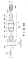
- the flow rate measuring system of this embodiment comprises a laser 201 which projects measuring light L onto light scattering fluid 200 flowing at a flow rate V, a frequency analysis means 202, and a signal analysis means 203 which forms a flow rate analysis means together with the frequency analysis means 202.
- the frequency analysis means 202 a condenser leans 210 which condenses the measuring light L scattered by the scattering fluid 200, a collimator lens 211 which parallels the scattered measuring light L condensed by the condenser lens 210, a condenser lens 212 which condenses the measuring light L paralleled by the collimator lens 211, a photodetector 213 which detects the measuring light L condensed by the condenser lens 212, and a pair of half-silvered mirrors 220 and 221 which are disposed between the collimator lens 211 and the condenser lens 212 and form a Fabry-Perot interferometer.
- the half-silvered mirror 220 is fixed whereas the half-silvered mirror 221 is moved back and forth in the direction of arrow H by a drive means not shown.
- the signal analysis means 203 comprises a computer system and a light detection signal SQ is input into the signal analysis means 203 from the photodetector 213.
- the measuring light L is projected onto the fluid 200.
- the measuring light L scattered by the fluid 200 is caused to impinge upon the photodetector 213 by the condenser lens 210, the collimator lens 211 and the condenser lens 212 and the amount of measuring light L is detected by the photodetector 213.
- light components at wavelengths (frequencies) which generate standing wave between the half-silvered mirrors 221 and 220 enhance each other by light interference, and the light components of the measuring light L at the frequencies are detected by the photodetector 213.
- the half-silvered mirror 221 is moved in one direction and the distance of the half-silvered mirror 221 from the half-silvered mirror 220 continuously changes, the frequency of the light components detected by the photodetector 213 continuously changes.
- the light detection signal QS output from the photodetector 213 as the half-silvered mirror 221 is moved in one direction represents the intensity E of the detected light component at each frequency.
- the relation between the frequency and the intensity E of the detected light component varies with the flow rate of the fluid 200 as shown in Figures 14A to 14D.
- Figures 14A to 14D respectively show the relations when the flow rate V of the fluid 200 is 0, V1, V2 and V3 ( V1 ⁇ V2 ⁇ V3 ).
- ⁇ represents the center frequency.
- the signal analysis means 203 receives the light detection signal QS and obtains the half width FWHM of the spectrum. Then the signal analysis means 203 determines the flow rate V on the basis of the relation between the half width FWHM and the flow rate V which has been empirically determined. The flow rate V thus determined is shown by a display means such as a liquid crystal panel.
- the flow rate V is determined on the basis of the spectrum half width FWHM of the detected light
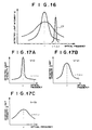
- the flow rate V may be determined on the basis of broadening of detected light spectrum by other methods. For instance, when the light detection signal QS output from the photodetector 213 is passed through a band-pass filter whose transmission characteristic is such that the center frequency is deviated from the center frequency ⁇ of the detected light by ⁇ (off-centered frequency components) as shown by curve c1 in Figure 16, the intensity of the frequency components transmitted through the band-pass filter is higher as the broadening of the spectrum increases, i.e., the flow rate V increases. Accordingly, the flow rate V can be obtained according to the intensity of the off-centered frequency components.
- the intensity ratio E( ⁇ + ⁇ )/E( ⁇ ) is obtained as shown in Figures 17A to 17C
- the intensity ratio is higher as the broadening of the spectrum increases, i.e., the flow rate V increases as shown in Figure 18. Accordingly, the flow rate V can be obtained according to the intensity ratio.
- the flow rate V can be determined according to the half width W.
- the intensity ratio I( ⁇ + ⁇ f)/I( ⁇ ) is higher as the Doppler broadening of the spectrum of the beat signal B increases, i.e., the flow rate V increases. Accordingly, the flow rate V can be obtained according to the intensity ratio.
Landscapes
- Health & Medical Sciences (AREA)
- Life Sciences & Earth Sciences (AREA)
- Heart & Thoracic Surgery (AREA)
- Medical Informatics (AREA)
- Physics & Mathematics (AREA)
- Cardiology (AREA)
- Biophysics (AREA)
- Pathology (AREA)
- Engineering & Computer Science (AREA)
- Biomedical Technology (AREA)
- Hematology (AREA)
- Physiology (AREA)
- Molecular Biology (AREA)
- Surgery (AREA)
- Animal Behavior & Ethology (AREA)
- General Health & Medical Sciences (AREA)
- Public Health (AREA)
- Veterinary Medicine (AREA)
- Measuring Pulse, Heart Rate, Blood Pressure Or Blood Flow (AREA)
- Investigating Or Analysing Materials By Optical Means (AREA)
Applications Claiming Priority (4)
| Application Number | Priority Date | Filing Date | Title |
|---|---|---|---|
| JP33076598 | 1998-11-20 | ||
| JP33076498 | 1998-11-20 | ||
| JP33076598 | 1998-11-20 | ||
| JP33076498 | 1998-11-20 |
Publications (3)
| Publication Number | Publication Date |
|---|---|
| EP1002497A2 true EP1002497A2 (fr) | 2000-05-24 |
| EP1002497A3 EP1002497A3 (fr) | 2001-05-16 |
| EP1002497B1 EP1002497B1 (fr) | 2006-07-26 |
Family
ID=26573631
Family Applications (1)
| Application Number | Title | Priority Date | Filing Date |
|---|---|---|---|
| EP99123025A Expired - Lifetime EP1002497B1 (fr) | 1998-11-20 | 1999-11-19 | Système d'imagerie de vaisseau sanguin |
Country Status (3)
| Country | Link |
|---|---|
| US (1) | US6374128B1 (fr) |
| EP (1) | EP1002497B1 (fr) |
| DE (1) | DE69932485T2 (fr) |
Cited By (1)
| Publication number | Priority date | Publication date | Assignee | Title |
|---|---|---|---|---|
| WO2006121408A1 (fr) * | 2005-05-12 | 2006-11-16 | Spectracure Ab | Dispositif, systeme et procede permettant de determiner l'effet de la therapie tumorale photodynamique ou photothermique |
Families Citing this family (102)
| Publication number | Priority date | Publication date | Assignee | Title |
|---|---|---|---|---|
| JP2000155090A (ja) * | 1998-11-20 | 2000-06-06 | Fuji Photo Film Co Ltd | 血管の画像化装置 |
| US6542246B1 (en) * | 1998-11-20 | 2003-04-01 | Fuji Photo Film Co., Ltd. | Blood vessel imaging system |
| US6556854B1 (en) | 1998-11-20 | 2003-04-29 | Fuji Photo Film Co., Ltd. | Blood vessel imaging system using homodyne and heterodyne effects |
| US8078263B2 (en) * | 2000-01-19 | 2011-12-13 | Christie Medical Holdings, Inc. | Projection of subsurface structure onto an object's surface |
| US7239909B2 (en) * | 2000-01-19 | 2007-07-03 | Luminetx Technologies Corp. | Imaging system using diffuse infrared light |
| ATE454845T1 (de) | 2000-10-30 | 2010-01-15 | Gen Hospital Corp | Optische systeme zur gewebeanalyse |
| US9295391B1 (en) | 2000-11-10 | 2016-03-29 | The General Hospital Corporation | Spectrally encoded miniature endoscopic imaging probe |
| WO2002088705A2 (fr) | 2001-05-01 | 2002-11-07 | The General Hospital Corporation | Procede et appareil pour determiner un type de plaque d'atherosclerose par mesure de proprietes optiques de tissu |
| US6939310B2 (en) * | 2001-10-10 | 2005-09-06 | Lifescan, Inc. | Devices for physiological fluid sampling and methods of using the same |
| US7024027B1 (en) * | 2001-11-13 | 2006-04-04 | Koninklijke Philips Electronics N.V. | Method and apparatus for three-dimensional filtering of angiographic volume data |
| US7355716B2 (en) * | 2002-01-24 | 2008-04-08 | The General Hospital Corporation | Apparatus and method for ranging and noise reduction of low coherence interferometry LCI and optical coherence tomography OCT signals by parallel detection of spectral bands |
| US20110201924A1 (en) * | 2002-04-30 | 2011-08-18 | The General Hospital Corporation | Method and Apparatus for Improving Image Clarity and Sensitivity in Optical Tomography Using Dynamic Feedback to Control Focal Properties and Coherence Gating |
| US7643153B2 (en) * | 2003-01-24 | 2010-01-05 | The General Hospital Corporation | Apparatus and method for ranging and noise reduction of low coherence interferometry LCI and optical coherence tomography OCT signals by parallel detection of spectral bands |
| CA2519937C (fr) | 2003-03-31 | 2012-11-20 | Guillermo J. Tearney | Reduction de granularite dans la tomographie par coherence optique au moyen d'une composition angulaire par codage de longueur de trajet |
| ES2310744T3 (es) * | 2003-06-06 | 2009-01-16 | The General Hospital Corporation | Fuente de luz sintonizable en longitudes de onda. |
| EP2278287B1 (fr) | 2003-10-27 | 2016-09-07 | The General Hospital Corporation | Procédé et appareil de l'imagerie optique avec de l'interférométrie dans le domaine de fréquence |
| US8160667B2 (en) * | 2003-11-26 | 2012-04-17 | Hitachi Medical Corporation | Biological light measuring apparatus and method |
| US8018598B2 (en) | 2004-05-29 | 2011-09-13 | The General Hospital Corporation | Process, system and software arrangement for a chromatic dispersion compensation using reflective layers in optical coherence tomography (OCT) imaging |
| AU2005270037B2 (en) | 2004-07-02 | 2012-02-09 | The General Hospital Corporation | Endoscopic imaging probe comprising dual clad fibre |
| JP5053845B2 (ja) * | 2004-08-06 | 2012-10-24 | ザ ジェネラル ホスピタル コーポレイション | 光学コヒーレンス断層撮影法を使用して試料中の少なくとも1つの位置を決定するための方法、システムおよびソフトウェア装置 |
| JP5324095B2 (ja) | 2004-08-24 | 2013-10-23 | ザ ジェネラル ホスピタル コーポレイション | 血管セグメントを画像化する方法および装置 |
| EP1989997A1 (fr) | 2004-08-24 | 2008-11-12 | The General Hospital Corporation | Procèdé, Système et logiciel pour la mesure de la contrainte mécanique et des propriétés élastiques d'un echantillon |
| US7365859B2 (en) | 2004-09-10 | 2008-04-29 | The General Hospital Corporation | System and method for optical coherence imaging |
| EP1804638B1 (fr) | 2004-09-29 | 2012-12-19 | The General Hospital Corporation | Systeme et procede d'imagerie a coherence optique |
| EP2278266A3 (fr) | 2004-11-24 | 2011-06-29 | The General Hospital Corporation | Interféromètre à chemin commun pour OCT endoscopique |
| WO2006058346A1 (fr) | 2004-11-29 | 2006-06-01 | The General Hospital Corporation | Ensembles, dispositifs, endoscopes, catheters et methodes d'imagerie optique permettant d'eclairer et de detecter simultanement plusieurs points sur un echantillon |
| US20070004976A1 (en) * | 2004-12-14 | 2007-01-04 | Zelenchuk Alex R | In vivo optical measurements of hematocrit |
| US20060129038A1 (en) * | 2004-12-14 | 2006-06-15 | Zelenchuk Alex R | Optical determination of in vivo properties |
| US7225005B2 (en) * | 2004-12-14 | 2007-05-29 | Intelligent Medical Devices, Inc. | Optical determination of in vivo properties |
| EP2325803A1 (fr) | 2005-04-28 | 2011-05-25 | The General Hospital Corporation | Evaluation des informations de tomographie par cohérence optique pour une structure anatomique |
| EP1888152A2 (fr) * | 2005-05-10 | 2008-02-20 | Koninklijke Philips Electronics N.V. | Systeme d'introduction de canule |
| EP1889037A2 (fr) | 2005-06-01 | 2008-02-20 | The General Hospital Corporation | Appareil, methode et systeme pour effectuer une imagerie de domaine de frequence optique a resolution de phase |
| DE602006017558D1 (de) | 2005-08-09 | 2010-11-25 | Gen Hospital Corp | Gerät und verfahren zur durchführung von polarisationsbasierter quadraturdemodulation bei optischer kohärenztomographie |
| EP1940286A1 (fr) | 2005-09-29 | 2008-07-09 | General Hospital Corporation | Procede et appareil destines a un procede pour visualiser et analyser un ou plusieurs echantillons biologiques avec des resolutions augmentant progressivement |
| JP5203951B2 (ja) | 2005-10-14 | 2013-06-05 | ザ ジェネラル ホスピタル コーポレイション | スペクトル及び周波数符号化蛍光画像形成 |
| US7796270B2 (en) * | 2006-01-10 | 2010-09-14 | The General Hospital Corporation | Systems and methods for generating data based on one or more spectrally-encoded endoscopy techniques |
| WO2007084903A2 (fr) | 2006-01-19 | 2007-07-26 | The General Hospital Corporation | Dispositif de collecte d'information pour une structure utilisant des techniques d'endoscopie à codage spectral, et procédé d'élaboration correspondant |
| CN101384212A (zh) | 2006-01-19 | 2009-03-11 | 通用医疗公司 | 通过上皮内腔器官束扫描对上皮内腔器官进行光学成像的方法和系统 |
| US10426548B2 (en) * | 2006-02-01 | 2019-10-01 | The General Hosppital Corporation | Methods and systems for providing electromagnetic radiation to at least one portion of a sample using conformal laser therapy procedures |
| US9186066B2 (en) | 2006-02-01 | 2015-11-17 | The General Hospital Corporation | Apparatus for applying a plurality of electro-magnetic radiations to a sample |
| EP3143926B1 (fr) * | 2006-02-08 | 2020-07-01 | The General Hospital Corporation | Procédés, agencements et systèmes pour obtenir des informations associées à un prélèvement anatomique utilisant la microscopie optique |
| JP2009527770A (ja) | 2006-02-24 | 2009-07-30 | ザ ジェネラル ホスピタル コーポレイション | 角度分解型のフーリエドメイン光干渉断層撮影法を遂行する方法及びシステム |
| US7742173B2 (en) | 2006-04-05 | 2010-06-22 | The General Hospital Corporation | Methods, arrangements and systems for polarization-sensitive optical frequency domain imaging of a sample |
| EP3150110B1 (fr) | 2006-05-10 | 2020-09-02 | The General Hospital Corporation | Processus, agencements et systèmes pour fournir une imagerie de domaine de fréquence d'un échantillon |
| US7782464B2 (en) | 2006-05-12 | 2010-08-24 | The General Hospital Corporation | Processes, arrangements and systems for providing a fiber layer thickness map based on optical coherence tomography images |
| EP2054712B1 (fr) | 2006-08-25 | 2015-10-07 | The General Hospital Corporation | Appareil et procédés permettant d'améliorer l'imagerie de tomographie par cohérence optique mettant en oeuvre des techniques de filtrage volumétrique |
| WO2008049118A2 (fr) | 2006-10-19 | 2008-04-24 | The General Hospital Corporation | Dispositif et procédé d'obtention et de fourniture d'informations d'image associées à au moins une portion d' échantillon et permettant de réaliser une telle portion |
| WO2008089342A1 (fr) | 2007-01-19 | 2008-07-24 | The General Hospital Corporation | Réflexion de disque rotatif pour balayage de longueurs d'onde rapide de lumière à large bande dispersée |
| WO2008089406A2 (fr) * | 2007-01-19 | 2008-07-24 | The General Hospital Corporation | Appareil et procédé pour contrôler la profondeur de télémétrie dans une imagerie de domaine de fréquence optique |
| EP2602651A3 (fr) | 2007-03-23 | 2014-08-27 | The General Hospital Corporation | Procédés, agencements et appareil pour utiliser un laser à balayage de longueur d'ondes utilisant un balayage angulaire et des procédures de dispersion |
| US10534129B2 (en) | 2007-03-30 | 2020-01-14 | The General Hospital Corporation | System and method providing intracoronary laser speckle imaging for the detection of vulnerable plaque |
| US8045177B2 (en) * | 2007-04-17 | 2011-10-25 | The General Hospital Corporation | Apparatus and methods for measuring vibrations using spectrally-encoded endoscopy |
| WO2009018456A2 (fr) | 2007-07-31 | 2009-02-05 | The General Hospital Corporation | Systèmes et procédés pour fournir des motifs de balayage de faisceau pour une imagerie dans le domaine de la fréquence optique doppler de vitesse élevée |
| EP2191254B1 (fr) | 2007-08-31 | 2017-07-19 | The General Hospital Corporation | Systeme et procede pour une microscopie par fluorescence a auto-interference, et support lisible par ordinateur associe à ceux-ci |
| WO2009059034A1 (fr) | 2007-10-30 | 2009-05-07 | The General Hospital Corporation | Système et procédé permettant une détection de mode de gaine |
| US7898656B2 (en) * | 2008-04-30 | 2011-03-01 | The General Hospital Corporation | Apparatus and method for cross axis parallel spectroscopy |
| US8593619B2 (en) | 2008-05-07 | 2013-11-26 | The General Hospital Corporation | System, method and computer-accessible medium for tracking vessel motion during three-dimensional coronary artery microscopy |
| JP5795531B2 (ja) | 2008-06-20 | 2015-10-14 | ザ ジェネラル ホスピタル コーポレイション | フューズドファイバオプティックカプラ構造、及びその使用方法 |
| WO2010009136A2 (fr) | 2008-07-14 | 2010-01-21 | The General Hospital Corporation | Appareil et procédés d'endoscopie couleur |
| US9414805B2 (en) * | 2008-07-28 | 2016-08-16 | Siemens Medical Solutions Usa, Inc. | Spectral Doppler with multiple spatially distinct gates |
| EP2359121A4 (fr) * | 2008-12-10 | 2013-08-14 | Gen Hospital Corp | Systèmes, appareil et procédés d'extension de la plage de profondeur d'imagerie de tomographie par cohérence optique, par le biais du sous-échantillonnage optique |
| WO2010090837A2 (fr) * | 2009-01-20 | 2010-08-12 | The General Hospital Corporation | Appareil, système et procédé de biopsie endoscopique |
| JP2012515930A (ja) | 2009-01-26 | 2012-07-12 | ザ ジェネラル ホスピタル コーポレーション | 広視野の超解像顕微鏡を提供するためのシステム、方法及びコンピューターがアクセス可能な媒体 |
| US8254023B2 (en) * | 2009-02-23 | 2012-08-28 | Visiongate, Inc. | Optical tomography system with high-speed scanner |
| US9351642B2 (en) | 2009-03-12 | 2016-05-31 | The General Hospital Corporation | Non-contact optical system, computer-accessible medium and method for measurement at least one mechanical property of tissue using coherent speckle technique(s) |
| BR112012001042A2 (pt) * | 2009-07-14 | 2016-11-22 | Gen Hospital Corp | equipamento e método de medição do fluxo de fluído dentro de estrutura anatômica. |
| EP2542145B1 (fr) | 2010-03-05 | 2020-08-12 | The General Hospital Corporation | Systèmes qui procurent des images microscopiques d'au moins une structure anatomique à une résolution particulière |
| US9069130B2 (en) | 2010-05-03 | 2015-06-30 | The General Hospital Corporation | Apparatus, method and system for generating optical radiation from biological gain media |
| EP2575597B1 (fr) | 2010-05-25 | 2022-05-04 | The General Hospital Corporation | Appareil pour fournir une imagerie optique de structures et de compositions |
| US9795301B2 (en) | 2010-05-25 | 2017-10-24 | The General Hospital Corporation | Apparatus, systems, methods and computer-accessible medium for spectral analysis of optical coherence tomography images |
| WO2011153434A2 (fr) | 2010-06-03 | 2011-12-08 | The General Hospital Corporation | Appareil et procédé pour dispositifs de structures d'imagerie, dans ou sur un ou plusieurs organes luminaux |
| JP5883018B2 (ja) | 2010-10-27 | 2016-03-09 | ザ ジェネラル ホスピタル コーポレイション | 少なくとも1つの血管内部の血圧を測定するための装置、システム、および方法 |
| WO2013013049A1 (fr) | 2011-07-19 | 2013-01-24 | The General Hospital Corporation | Systèmes, procédés, appareils et supports accessibles par ordinateur permettant de produire une compensation de dispersion en mode polarisation dans la tomographie à cohérence optique |
| EP2748587B1 (fr) | 2011-08-25 | 2021-01-13 | The General Hospital Corporation | Procédés et arrangements permettant de mettre en oeuvre des procédures de tomographie par cohérence micro-optique |
| US9341783B2 (en) | 2011-10-18 | 2016-05-17 | The General Hospital Corporation | Apparatus and methods for producing and/or providing recirculating optical delay(s) |
| US11399898B2 (en) | 2012-03-06 | 2022-08-02 | Briteseed, Llc | User interface for a system used to determine tissue or artifact characteristics |
| US9629528B2 (en) | 2012-03-30 | 2017-04-25 | The General Hospital Corporation | Imaging system, method and distal attachment for multidirectional field of view endoscopy |
| EP2852315A4 (fr) | 2012-05-21 | 2016-06-08 | Gen Hospital Corp | Appareil, dispositif et procédé pour microscopie par capsule |
| US9968261B2 (en) | 2013-01-28 | 2018-05-15 | The General Hospital Corporation | Apparatus and method for providing diffuse spectroscopy co-registered with optical frequency domain imaging |
| US10893806B2 (en) | 2013-01-29 | 2021-01-19 | The General Hospital Corporation | Apparatus, systems and methods for providing information regarding the aortic valve |
| WO2014121082A1 (fr) | 2013-02-01 | 2014-08-07 | The General Hospital Corporation | Agencement d'objectif pour endomicroscopie confocale |
| WO2014144709A2 (fr) | 2013-03-15 | 2014-09-18 | The General Hospital Corporation | Procédés et systèmes de caractérisation d'objet |
| EP2997354A4 (fr) | 2013-05-13 | 2017-01-18 | The General Hospital Corporation | Détection de la phase et de l'amplitude d'une fluorescence auto-interférente |
| EP3021735A4 (fr) | 2013-07-19 | 2017-04-19 | The General Hospital Corporation | Détermination de mouvement oculaire au moyen d'une imagerie de la rétine avec rétroaction d'un mouvement de l'oeil par imagerie de la rétine et fournir des informations en retour pour l'acquisition de signaux venant de la rétine |
| WO2015009932A1 (fr) | 2013-07-19 | 2015-01-22 | The General Hospital Corporation | Appareil d'imagerie et procédé utilisant une endoscopie à champ de vision multidirectionnel |
| WO2015013651A2 (fr) | 2013-07-26 | 2015-01-29 | The General Hospital Corporation | Système, appareil et procédé utilisant une dispersion optique pour réaliser une tomographie en cohérence optique dans le domaine de fourier |
| WO2015105870A1 (fr) | 2014-01-08 | 2015-07-16 | The General Hospital Corporation | Procédé et appareil pour imagerie microscopique |
| US10736494B2 (en) | 2014-01-31 | 2020-08-11 | The General Hospital Corporation | System and method for facilitating manual and/or automatic volumetric imaging with real-time tension or force feedback using a tethered imaging device |
| EP3122237B1 (fr) | 2014-03-25 | 2018-10-17 | Briteseed, LLC | Détecteur de vaisseaux et procédé de détection |
| US10228556B2 (en) | 2014-04-04 | 2019-03-12 | The General Hospital Corporation | Apparatus and method for controlling propagation and/or transmission of electromagnetic radiation in flexible waveguide(s) |
| JP2017525435A (ja) | 2014-07-25 | 2017-09-07 | ザ ジェネラル ホスピタル コーポレイション | インビボ・イメージングおよび診断のための機器、デバイスならびに方法 |
| JP6841770B2 (ja) * | 2015-02-03 | 2021-03-10 | ヴァンダービルト ユニヴァーシティ | 静脈漏出および静脈の中の設置を検出する静脈内アクセス・デバイス |
| ES2907824T3 (es) | 2015-02-19 | 2022-04-26 | Briteseed Llc | Sistema para determinar el borde de un vaso |
| US10820838B2 (en) | 2015-02-19 | 2020-11-03 | Briteseed, Llc | System for determining vessel size using light absorption |
| JP7057277B2 (ja) | 2015-10-08 | 2022-04-19 | ブライトシード・エルエルシー | 脈管サイズを決定するシステム及びその方法 |
| US11069054B2 (en) | 2015-12-30 | 2021-07-20 | Visiongate, Inc. | System and method for automated detection and monitoring of dysplasia and administration of immunotherapy and chemotherapy |
| JP6951348B2 (ja) | 2016-02-12 | 2021-10-20 | ブライトシード・エルエルシーBriteseed,Llc | 組織特性を決定するためのシステム及び方法 |
| JP2017153875A (ja) * | 2016-03-04 | 2017-09-07 | セイコーエプソン株式会社 | 生体情報測定装置および生体情報測定方法 |
| EP3506815B1 (fr) | 2016-08-30 | 2022-03-09 | Briteseed, LLC | Système optique chirugical avec des pinces non-parallèle avec compensation de distorsion angulaire |
| EP3678535B1 (fr) | 2017-09-05 | 2021-11-03 | Briteseed, LLC | Système et procédé utilisés pour déterminer des caractéristiques de tissu et/ou d'artéfact |
| JP7313353B2 (ja) | 2017-12-22 | 2023-07-24 | ブライトシード・エルエルシー | 組織又はアーチファクト特性を決定するために使用される小型システム |
| EP3902471B1 (fr) | 2018-12-30 | 2024-09-18 | Briteseed, LLC | Système utilisé pour détecter ou différencier un tissu ou un artefact |
Family Cites Families (9)
| Publication number | Priority date | Publication date | Assignee | Title |
|---|---|---|---|---|
| US4109647A (en) * | 1977-03-16 | 1978-08-29 | The United States Of America As Represented By The Secretary Of The Department Of Health, Education And Welfare | Method of and apparatus for measurement of blood flow using coherent light |
| GB2132483B (en) * | 1982-04-07 | 1986-02-12 | Univ Manchester | A device for measuring blood flow |
| US4834111A (en) * | 1987-01-12 | 1989-05-30 | The Trustees Of Columbia University In The City Of New York | Heterodyne interferometer |
| US5022757A (en) * | 1989-01-23 | 1991-06-11 | Modell Mark D | Heterodyne system and method for sensing a target substance |
| US5022157A (en) | 1990-07-30 | 1991-06-11 | Andy Chang | Transmission mechanism for scroll sawing machine |
| US5106184A (en) * | 1990-08-13 | 1992-04-21 | Eye Research Institute Of Retina Foundation | Retinal laser doppler apparatus having eye tracking system |
| US5321501A (en) * | 1991-04-29 | 1994-06-14 | Massachusetts Institute Of Technology | Method and apparatus for optical imaging with means for controlling the longitudinal range of the sample |
| IL113333A (en) * | 1995-04-11 | 2001-01-28 | Yoav Paltieli | Fiber-optic endoscope |
| US6037579A (en) * | 1997-11-13 | 2000-03-14 | Biophotonics Information Laboratories, Ltd. | Optical interferometer employing multiple detectors to detect spatially distorted wavefront in imaging of scattering media |
-
1999
- 1999-11-19 DE DE69932485T patent/DE69932485T2/de not_active Expired - Lifetime
- 1999-11-19 EP EP99123025A patent/EP1002497B1/fr not_active Expired - Lifetime
- 1999-11-22 US US09/444,378 patent/US6374128B1/en not_active Expired - Lifetime
Cited By (1)
| Publication number | Priority date | Publication date | Assignee | Title |
|---|---|---|---|---|
| WO2006121408A1 (fr) * | 2005-05-12 | 2006-11-16 | Spectracure Ab | Dispositif, systeme et procede permettant de determiner l'effet de la therapie tumorale photodynamique ou photothermique |
Also Published As
| Publication number | Publication date |
|---|---|
| US6374128B1 (en) | 2002-04-16 |
| DE69932485T2 (de) | 2007-01-11 |
| DE69932485D1 (de) | 2006-09-07 |
| EP1002497A3 (fr) | 2001-05-16 |
| EP1002497B1 (fr) | 2006-07-26 |
Similar Documents
| Publication | Publication Date | Title |
|---|---|---|
| EP1002497B1 (fr) | Système d'imagerie de vaisseau sanguin | |
| US6542246B1 (en) | Blood vessel imaging system | |
| US6556854B1 (en) | Blood vessel imaging system using homodyne and heterodyne effects | |
| US6757555B2 (en) | Ophthalmologic apparatus | |
| TWI463177B (zh) | 使用頻率域干涉法用以執行光學成像之方法及設備 | |
| EP0808605B1 (fr) | Détecteur pour chercher le point optimalisé pour le diagnostic non invasif des constituants du sang | |
| US7061622B2 (en) | Aspects of basic OCT engine technologies for high speed optical coherence tomography and light source and other improvements in optical coherence tomography | |
| US7023558B2 (en) | Acousto-optic monitoring and imaging in a depth sensitive manner | |
| US7245383B2 (en) | Optical image measuring apparatus for obtaining a signal intensity and spatial phase distribution of interference light | |
| US7751056B2 (en) | Optical coherence tomographic imaging apparatus | |
| US6522911B1 (en) | Apparatus for imaging a blood vessel | |
| EP0826958A2 (fr) | Procédé et dispositif d'obtention d'informations sur l'absorption optique d'un milieu diffusant | |
| WO1997043950A1 (fr) | Appareil de visualisation de l'ecoulement sanguin dans des vaisseaux de petit calibre | |
| US5778878A (en) | Laser doppler microscopy methods and instruments | |
| JP3471788B1 (ja) | 酸素飽和度測定装置 | |
| JP3500216B2 (ja) | 電圧測定装置 | |
| JP3076016B2 (ja) | 光計測装置 | |
| JP3844629B2 (ja) | 血管の画像化装置 | |
| EP1447651A1 (fr) | Dispositif de mesure optique avec une source d'éclairage sélective en longueur d'onde | |
| JP4040224B2 (ja) | 血管の画像化装置並びに脈波信号の空間分布測定方法および装置 | |
| JP3264463B2 (ja) | 光散乱媒体の吸光計測装置 | |
| JP2006239444A (ja) | 血管の画像化装置および血管の識別装置並びに散乱流体の流速測定装置 | |
| JP2006239444A5 (fr) | ||
| EP3205976A1 (fr) | Tomographie en cohérence optique à faisceaux multiples codée par longueur d'onde | |
| JP3390243B2 (ja) | 光散乱媒体の吸光情報検出方法 |
Legal Events
| Date | Code | Title | Description |
|---|---|---|---|
| PUAI | Public reference made under article 153(3) epc to a published international application that has entered the european phase |
Free format text: ORIGINAL CODE: 0009012 |
|
| AK | Designated contracting states |
Kind code of ref document: A2 Designated state(s): DE FR NL |
|
| AX | Request for extension of the european patent |
Free format text: AL;LT;LV;MK;RO;SI |
|
| PUAL | Search report despatched |
Free format text: ORIGINAL CODE: 0009013 |
|
| AK | Designated contracting states |
Kind code of ref document: A3 Designated state(s): AT BE CH CY DE DK ES FI FR GB GR IE IT LI LU MC NL PT SE |
|
| AX | Request for extension of the european patent |
Free format text: AL;LT;LV;MK;RO;SI |
|
| 17P | Request for examination filed |
Effective date: 20010709 |
|
| AKX | Designation fees paid |
Free format text: DE FR NL |
|
| 17Q | First examination report despatched |
Effective date: 20031126 |
|
| GRAP | Despatch of communication of intention to grant a patent |
Free format text: ORIGINAL CODE: EPIDOSNIGR1 |
|
| GRAS | Grant fee paid |
Free format text: ORIGINAL CODE: EPIDOSNIGR3 |
|
| GRAA | (expected) grant |
Free format text: ORIGINAL CODE: 0009210 |
|
| AK | Designated contracting states |
Kind code of ref document: B1 Designated state(s): DE FR NL |
|
| REF | Corresponds to: |
Ref document number: 69932485 Country of ref document: DE Date of ref document: 20060907 Kind code of ref document: P |
|
| ET | Fr: translation filed | ||
| RAP2 | Party data changed (patent owner data changed or rights of a patent transferred) |
Owner name: FUJIFILM CORPORATION |
|
| PLBE | No opposition filed within time limit |
Free format text: ORIGINAL CODE: 0009261 |
|
| STAA | Information on the status of an ep patent application or granted ep patent |
Free format text: STATUS: NO OPPOSITION FILED WITHIN TIME LIMIT |
|
| NLT2 | Nl: modifications (of names), taken from the european patent patent bulletin |
Owner name: FUJIFILM CORPORATION Effective date: 20070502 |
|
| 26N | No opposition filed |
Effective date: 20070427 |
|
| REG | Reference to a national code |
Ref country code: FR Ref legal event code: TP Ref country code: FR Ref legal event code: CD |
|
| REG | Reference to a national code |
Ref country code: FR Ref legal event code: PLFP Year of fee payment: 17 |
|
| PGFP | Annual fee paid to national office [announced via postgrant information from national office to epo] |
Ref country code: DE Payment date: 20151110 Year of fee payment: 17 |
|
| PGFP | Annual fee paid to national office [announced via postgrant information from national office to epo] |
Ref country code: NL Payment date: 20151012 Year of fee payment: 17 Ref country code: FR Payment date: 20151008 Year of fee payment: 17 |
|
| REG | Reference to a national code |
Ref country code: DE Ref legal event code: R119 Ref document number: 69932485 Country of ref document: DE |
|
| REG | Reference to a national code |
Ref country code: NL Ref legal event code: MM Effective date: 20161201 |
|
| REG | Reference to a national code |
Ref country code: FR Ref legal event code: ST Effective date: 20170731 |
|
| PG25 | Lapsed in a contracting state [announced via postgrant information from national office to epo] |
Ref country code: NL Free format text: LAPSE BECAUSE OF NON-PAYMENT OF DUE FEES Effective date: 20161201 |
|
| PG25 | Lapsed in a contracting state [announced via postgrant information from national office to epo] |
Ref country code: FR Free format text: LAPSE BECAUSE OF NON-PAYMENT OF DUE FEES Effective date: 20161130 |
|
| PG25 | Lapsed in a contracting state [announced via postgrant information from national office to epo] |
Ref country code: DE Free format text: LAPSE BECAUSE OF NON-PAYMENT OF DUE FEES Effective date: 20170601 |