EP1002502A1 - Verfahren und Vorrichtung zur Unterstützung des Positionierens und Ausrichtens eines manuell frei bewegbaren Werkzeuges - Google Patents
Verfahren und Vorrichtung zur Unterstützung des Positionierens und Ausrichtens eines manuell frei bewegbaren Werkzeuges Download PDFInfo
- Publication number
- EP1002502A1 EP1002502A1 EP99122880A EP99122880A EP1002502A1 EP 1002502 A1 EP1002502 A1 EP 1002502A1 EP 99122880 A EP99122880 A EP 99122880A EP 99122880 A EP99122880 A EP 99122880A EP 1002502 A1 EP1002502 A1 EP 1002502A1
- Authority
- EP
- European Patent Office
- Prior art keywords
- tool
- entry point
- picture elements
- point
- volume picture
- Prior art date
- Legal status (The legal status is an assumption and is not a legal conclusion. Google has not performed a legal analysis and makes no representation as to the accuracy of the status listed.)
- Granted
Links
Images

Classifications
-
- A—HUMAN NECESSITIES
- A61—MEDICAL OR VETERINARY SCIENCE; HYGIENE
- A61B—DIAGNOSIS; SURGERY; IDENTIFICATION
- A61B90/00—Instruments, implements or accessories specially adapted for surgery or diagnosis and not covered by any of the groups A61B1/00 - A61B50/00, e.g. for luxation treatment or for protecting wound edges
- A61B90/36—Image-producing devices or illumination devices not otherwise provided for
-
- A—HUMAN NECESSITIES
- A61—MEDICAL OR VETERINARY SCIENCE; HYGIENE
- A61B—DIAGNOSIS; SURGERY; IDENTIFICATION
- A61B34/00—Computer-aided surgery; Manipulators or robots specially adapted for use in surgery
- A61B34/10—Computer-aided planning, simulation or modelling of surgical operations
-
- A—HUMAN NECESSITIES
- A61—MEDICAL OR VETERINARY SCIENCE; HYGIENE
- A61B—DIAGNOSIS; SURGERY; IDENTIFICATION
- A61B90/00—Instruments, implements or accessories specially adapted for surgery or diagnosis and not covered by any of the groups A61B1/00 - A61B50/00, e.g. for luxation treatment or for protecting wound edges
- A61B90/36—Image-producing devices or illumination devices not otherwise provided for
- A61B90/37—Surgical systems with images on a monitor during operation
Definitions
- the invention relates to a method and an apparatus for supporting the Positioning and aligning a manually freely movable one longitudinal axis having tool relative to an object to be processed. application This method is particularly found in image-guided surgery, namely in the preoperative phase and in the phase up to immediately before the intervention and if necessary, also during the procedure.
- Image guided surgery is a novel approach to improve Safety and effectiveness of surgical interventions.
- This technique uses preoperative images such as ultrasound, computed tomography (CT) or Magnetic Resonance Imaging (MRI). This information is used for therapy planning and intraoperative control of the position of surgical instruments used.
- CT computed tomography
- MRI Magnetic Resonance Imaging
- This information is used for therapy planning and intraoperative control of the position of surgical instruments used.
- these systems can do this contribute instruments to the target tissue, e.g. a brain tumor. Examples of such systems are in EP-A-0 427 358 and EP-A-0 830 847 described.
- Interventional MRI devices can do this.
- preoperative Tomograms three-dimensional data records of images taken from inside the object Volume picture elements
- Interventionally created tomograms suffer from the cutting plane including that only layer images of comparatively poor quality and can be generated with a time delay (of a few seconds).
- the surgeon is only Cross-sectional images shown that show the device level without context and target structures. It generally takes about 5 seconds or more to build up the image. Without Orientation aids are extremely difficult for the surgeon starting from one on the object to be processed, for example head, with a defined entry point to get the surgical instrument to the processing point (target structure).
- the invention has for its object to a method and an apparatus create that the positioning and alignment of a manually free movable tool relative to an object to be processed by cognitive adequate visual support.
- a mission statement is created based on prior to editing volume image elements obtained is generated and in which the tool in the Projection when viewing the image plane is also displayed.
- On the mission statement is marks the entry point on the surface of the object.
- the one in the The guiding principle of the sectional plane shown (hereinafter also the entry point sectional plane called) runs perpendicular to the connecting line between the entry point and the processing point, which in turn is inside the object and previously at Examination of the volume picture elements and the resulting different ones Section planes have been set.
- Using the coordinates of the Processing point and the entry point can calculate this connecting line so that then based on the volume picture elements obtained before processing the section plane that can be displayed in the desired angle to the connecting line and the entry point includes.
- the tool comes with a detector to detect the Provide tool position and orientation relative to the object to be treated. Based on this detection, it is now possible to place the tool in front of the model Entry point cutting plane according to its current positioning and To represent alignment in the projection. Because of this visualization, it is now possible for the processor to align the manually movable tool so that it has a predeterminable position relative to the object. In particular it is possible the longitudinal axis of the tool with the connecting line between Align processing point and entry point in alignment. Because the entry point cutting plane even runs perpendicular to the connecting line, the Representation of the tool in the mission statement at a point, since the tool in the Projection and thus is shown in the direction of its longitudinal axis.
- the mission statement serves as a kind Aiming device and thus supports the positioning and alignment of the Tool relative to the object to be treated.
- volume picture elements which are each displayed as a mission statement. Because the previously won Data records are not necessarily those currently found during treatment Conditions of the object must match, it is appropriate to add an additional Display control image based on currently acquired volume image elements is generated and shows sectional images that are adjustable in a predetermined Alignment relative to the tool. During prepositioning and Pre-alignment realized using the volume picture elements previously obtained the insertion of the tool into the object is optically via the Control picture controls, the positioning and alignment of the Introduction of the tool can in turn be supported based on the mission statement can.
- Fig. 1 The invention is particularly clear when you look at its application in a Tomograph in front of your eyes.
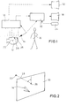
- the resulting overall system is shown schematically in Fig. 1
- Tomographs create three-dimensional data sets (tomograms) that do Show interior of closed objects. This makes it minimally invasive Interventions on inner target structures possible without significantly increasing the object itself to destroy.
- One example is the minimally invasive treatment of brain tumors Help from magnetic resonance tomographs.
- Interventional tomographs 10 allow, in addition to a preoperative raised tomogranim, cutting planes running continuously during the procedure To collect object 12, which indicate the current state.
- the position of the Section planes become one with a position and relative to the current position Alignment detector 13 provided surgical device (indicated at 14) This means that interventions can also be carried out and checked at which can deform the inside of the object 12 due to the engagement.
- the following embodiment describes a stereotactic Image guide procedure, the intraoperative sectional plane with the preoperative raised tomogram and synthetic control aids integrated so that positioning, alignment and movement of the Surgical device 14 (e.g. a catheter) quickly, safely and ergonomically optimal can be carried out and controlled.
- the Surgical device 14 e.g. a catheter
- the image guidance procedure for interventions in the interventional tomograph under intraoperative image control works according to the following scheme.
- the examination object 12 is in the interventional tomograph brought in and a tomogram collected. Then in the tomogram Target marked.
- the surgeon visualizes 16 (level by level or as a volume) the tomogram in the guidance monitor 18 of the image guidance system computer 20 until it interactively found the target position 22 in the tomogram.
- One through a data entry device 24 entered marking marked in three-dimensional volume the target position found 22.
- the surgeon 16 then marks the entry point 26.
- the visualizes Operator 16 (layer by layer or as volume) the tomogram in the mission monitor 18 of the image guidance system computer 20 until it interactively finds a suitable one Has found entry position 26.
- the entry can also take place on the real one Object can be identified with a position encoder.
- a mark in the three-dimensional volume marks the entry position 26.
- the entry point is opened at object 12.
- the surgical instrument 14 must be aligned with the real object 12 in this way be that it enters the object 12 at the marked entry point 26 and in the three-dimensional space is guided exactly in the direction of the target 22.
- the Positioning and alignment of the instrument 14 is current in interventional Systems a problem and a very elaborate and complicated action, because the operator 16 is not provided with any suitable orientation aids become. Only a two-dimensional sectional image becomes parallel or offered perpendicular to the instrument 14, which also arrives only after a delay.
- Fig. 3 shows a not yet optimal alignment and positioning of the Surgical instrument 14 relative to the entry point 26.
- the surgical instrument 14 is optimally positioned when the tip lies in the entry mark 26 (Figs. 4 and 5) and optimally aligned when its projection into a circle will (Fig. 5).
- the test is simplified according to the invention by simultaneously displaying the images corresponding to the current images of the control image monitor 32 from the preoperative tomogram on the mission monitor 32, which is generally a have better image resolution and also markings for the intended ones Have entry and destination points 26,22.
- This test can be carried out continuously when the surgical instrument 14 is inserted be continued.
- the sectional images from the preoperative Tomogram on the mission monitor 18 quick feedback while the slower and lower quality intraoperative images on the Control image monitor 32 for verification of the procedure at critical points be involved.
Landscapes
- Health & Medical Sciences (AREA)
- Surgery (AREA)
- Life Sciences & Earth Sciences (AREA)
- Heart & Thoracic Surgery (AREA)
- Molecular Biology (AREA)
- Oral & Maxillofacial Surgery (AREA)
- Engineering & Computer Science (AREA)
- Biomedical Technology (AREA)
- Nuclear Medicine, Radiotherapy & Molecular Imaging (AREA)
- Medical Informatics (AREA)
- Pathology (AREA)
- Animal Behavior & Ethology (AREA)
- General Health & Medical Sciences (AREA)
- Public Health (AREA)
- Veterinary Medicine (AREA)
- Apparatus For Radiation Diagnosis (AREA)
- Magnetic Resonance Imaging Apparatus (AREA)
Abstract
Description
- vor der Bearbeitung Volumenbildelemente von dem Innern des Objekts aufgenommen und gespeichert werden,
- anhand der angezeigten, zuvor aufgenommenen Volumenbildelemente eine im Innern des Objekts liegende Bearbeitungsstelle aufgefunden und mindestens eines der die Bearbeitungsstelle wiedergebenden Volumenbildelemente markiert wird,
- anhand der angezeigten, zuvor aufgenommenen Volumenbildelemente eine auf der Oberseite des Objekts liegende Eintrittsstelle zum Einführen des Werkzeuges festgelegt und markiert wird, wobei diese Eintrittsstelle entweder am zuvor aufgenommenen Objekt bereits markiert war oder mindestens eines der die Eintrittsstelle wiedergebenden Volumenbildelemente nach der Festlegung markiert wird,
- anhand der zuvor aufgenommenen Volumenbildelemente diejenige Eintrittsstellen-Schnittebene des Objekts angezeigt wird, die senkrecht zur Verbindungslinie zwischen der Behandlungsstelle und der Eintrittsstelle verläuft und die die Eintrittsstelle beinhaltet,
- die Position und Ausrichtung des Werkzeuges relativ zum Objekt detektiert wird und
- in der Darstellung der Eintrittsstellen-Schnittebene das Werkzeug insbesondere in stilisierter Form mit dargestellt wird, und zwar als Projektion bei Betrachtung in Richtung auf die Eintrittsstellen-Schnittebene vor dieser perspektivisch angeordnet,
- wobei das Werkzeug anhand der Darstellung der Eintrittsstellen-Schnittebene als Leitbild mit davor dargestellter Werkzeugprojektion so lange positioniert und ausgerichtet werden kann, bis diejenige Werkzeugausrichtung und -positionierung erreicht ist, bei die Längsachse des Werkzeuges mit der Verbindungslinie zwischen der Bearbeitungsstelle und der Eintrittsstelle fluchtet
- einer Verarbeitungseinheit zum Speichern und Verarbeiten von Volumenbildelementen vom Innern des Objekts ,
- einer Anzeigevorrichtung zum Anzeigen der gespeicherten Volumenbildelemente,
- einer Dateneingabevorrichtung zum Markieren einer Bearbeitungsstelle im Innern des Objekts und zum Markieren einer Eintrittsstelle auf der Oberseite des Objekts zum Einführen des Werkzeuges und als Zugang zur Bearbeitungsstelle für das Werkzeug, wobei die Bearbeitungs- und die Eintrittsstelle anhand der von der Anzeigevorrichtung angezeigten gespeicherten Volumenbildelementen des Objekts markierbar und in der Verarbeitungseinheit speicherbar sind, und
- einem Detektor für das Werkzeug zur Detektion der Position und Ausrichtung des Werkzeuges (relativ zum Objekt), und zum Liefern von Positions- und Ausrichtungsdaten an die Verarbeitungseinheit, wobei
- die Anzeigevorrichtung von der Verarbeitungseinheit derart ansteuerbar ist,
dass
- auf der Basis der gespeicherten Volumenbildelemente und der gespeicherten Eintrittsstelle diese sowie diejenige Eintrittsstellen-Schnittebene des Objekts, die senkrecht zur Verbindungslinie zwischen der Bearbeitungsstelle und der Eintrittsstelle verläuft und die Eintrittsstelle beinhaltet, darstellbar sind,
- und dass in dieser Darstellung der Eintrittsstellen-Schnittebene auch eine Repräsentation des Werkzeuges mit anzeigbar ist, und zwar als Projektion bei Betrachtung in Richtung auf die Eintrittsstellen-Schnittebene und vor dieser angeordnet, so dass das Werkzeug anhand der Darstellung der Eintrittsstellen-Schnittebene als Leitbild mit davor dargestellter Werkzeugprojektion so lange positioniert und ausgerichtet werden kann, bis die Längsachse des Werkzeuges mit der Verbindungslinie zwischen der Bearbeitungsstelle und der Eintrittsstelle fluchtet.
- Fig. 1
- eine schematische Darstellung des Systems für das stereotaktische Bildleitverfahren für Eingriffe mit interventionellen Tomographen unter intraoperativer Bildkontrolle,
- Fig. 2
- schematisch die geometrischen Elemente, die zur Ausrichtung benötigt werden, nämlich Eintrittsstelle, Zielstelle oder Behandlungsstelle und Instrument in einem integrierten Szenario und
- Fign. 3 bis 5
- verschiedene Darstellungen von Leitbildern zum Ausrichten des Operationsinstruments bei beliebiger Ausgangsposition (Fig. 3), bei korrekt an der Eintrittsstelle positionierter Spitze des Instruments (Fig. 4) und bei fluchtender Ausrichtung der Achse des Instruments mit der Verbindungslinie zwischen der Eintrittsstelle und der Ziel- bzw. Bearbeitungsstelle.
- Schnittebene durch den Eintritt senkrecht zur Verbindungslinie 28 (siehe Fign. 1 und 2) von Eintritt 26 zum Ziel 22 (Projektionsebene 30).
- Markierung des Eintritts 26 im Schnittbild. Das Ziel liegt im 3D-Raum senkrecht unter diesem Punkt.
- Die Projektion des Operationsinstruments 14 in aktuell gemessener Position und Ausrichtung.
Claims (8)
- Verfahren zur Unterstützung des Positionierens und Ausrichtens eines manuell frei bewegbaren, eine Längsachse aufweisenden Werkzeuges relativ zu einem zu behandelnden Objekt, bei demvor der Bearbeitung Volumenbildelemente von dem Innern des Objekts (12) aufgenommen und gespeichert werden,anhand der angezeigten, zuvor aufgenommenen Volumenbildelemente eine im Innern des Objekts (12) liegende Bearbeitungsstelle (22) aufgefunden und mindestens eines der die Bearbeitungsstelle (22) wiedergebenden Volumenbildelemente markiert wird,anhand der angezeigten, zuvor aufgenommenen Volumenbildelemente eine auf der Oberseite des Objekts (12) liegende Eintrittsstelle (26) zum Einführen Werkzeuges (14) festgelegt und markiert wird, wobei diese Eintrittsstelle (26) entweder am zuvor aufgenommenen Objekt (12) bereits markiert war oder mindestens eines der die Eintrittsstelle (26) wiedergebenden Volumenbildelemente nach der Festlegung markiert wird,anhand der zuvor aufgenommenen Volumenbildelemente diejenige Eintrittsstellen-Schnittebene des Objekts (12) angezeigt wird, senkrecht zur Verbindungslinie (28) zwischen der Bearbeitungsstelle (22) und der Eintrittsstelle (26) verläuft und die die Eintrittsstelle (26) beinhaltet,die Position und Ausrichtung des Werkzeuges (14) relativ zum Objekt (12) detektiert wird undin der Darstellung der Eintrittsstellen-Schnittebene das Werkzeug (14) insbesondere in stilisierter Form mit dargestellt wird, und zwar als Projektion bei Betrachtung in Richtung auf die Eintrittsstellen-Schnittebene vor dieser perspektivisch angeordnet,wobei das Werkzeug (14) anhand der Darstellung der Eintrittsstellen-Schnittebene als Leitbild mit davor dargestellter Werkzeugprojektion so lange positioniert und ausgerichtet werden kann, bis die Längsachse des Werkzeuges (14) mit der Verbindungslinie (28) zwischen der Bearbeitungsstelle (22) und der Eintrittsstelle (26) fluchtet.
- Verfahren nach Anspruch 1, dadurch gekennzeichnet, dass auf eine Darstellung des Objekts (12) mit Werkzeug (14) umgeschaltet werden kann, die anhand der zuvor aufgenommenen Volumenbildelemente erzeugt wird und die eine die Verbindungslinie (28) zwischen der Bearbeitungsstelle (22) und der Eintrittsstelle (26) beinhaltende Schnittebene zeigt.
- Verfahren nach Anspruch 1 oder 2, dadurch gekennzeichnet, dass beim Eindringen des Werkzeuges (14) in das Objekt (12) insbesondere zusätzlich eine Darstellung von Schnittebenen als Kontrollbild gezeigt wird, die vorbestimmte einstellbare Ausrichtungen relativ zum Werkzeug (14) aufweisen und anhand von aktuell vom Objekt (12) aufgenommenen Volumenbildelementen erzeugt werden.
- Verfahren nach einem der Ansprüche 1 bis 3, dadurch gekennzeichnet, dass beim Eindringen des Werkzeuges (14) in das Objekt (12) insbesondere zusätzlich eine Darstellung von Schnittebenen als Leitbild gezeigt wird, die vorbestimmte einstellbare Ausrichtungen relativ zum Werkzeug (14) aufweisen und anhand der zuvor vom Objekt (12) aufgenommenen Volumenbildelemente erzeugt werden.
- Vorrichtung zur Unterstützung des Positionierens und Ausrichtens eines manuell frei bewegbaren, eine Längsachse aufweisenden Werkzeuges relativ zu einem zu behandelnden Objekt, miteiner Verarbeitungseinheit (20) zum Speichern und Verarbeiten von Volumenbildelementen vom Innern des Objekts (12)einer Anzeigevorrichtung (18) zum Anzeigen der gespeicherten Volumenbildelemente,einer Dateneingabevorrichtung (24) zum Markieren einer Bearbeitungsstelle (22) im Innern des Objekts (12) und zum Markieren einer Eintrittsstelle (26) auf der Oberseite des Objekts (12) zum Einführen des Werkzeuges (14) und als Zugang zur Bearbeitungsstelle (22) durch das Werkzeug (14), wobei die Bearbeitungs- und die Eintrittsstelle (22,26) anhand der von der Anzeigevorrichtung (18) angezeigten gespeicherten Volumenbildelementen des Objekts (12) markierbar und in der Verarbeitungseinheit (20) speicherbar sind, undeinem Detektor (13) für das Werkzeug (14) zur Detektion der Position und Ausrichtung des Werkzeuges (14) relativ zum Objekt, und zum Liefern von Positions- und Ausrichtungsdaten an die Verarbeitungseinheit (20), wobeivon der Verarbeitungseinheit (20) die Anzeigevorrichtung (18) derart ansteuerbar ist, dassauf der Basis der gespeicherten Volumenbildelemente und der gespeicherten Eintrittsstelle diese sowie diejenige Eintrittsstellen-Schnittebene des Objekts (12), die senkrecht zur Verbindungslinie (28) zwischen der Bearbeitungsstelle (22) und der Eintrittsstelle (26) verläuft und die Eintrittsstelle (26) beinhaltet, darstellbar sind,und dass in dieser Darstellung der Eintrittsstellen-Schnittebene auch eine Repräsentation des Werkzeuges (14) mit anzeigbar ist, und zwar als Projektion bei Betrachtung in Richtung auf die Eintrittsstellen-Schnittebene und vor dieser angeordnet, so dass das Werkzeug (14) anhand der Darstellung der Eintrittsstellen-Schnittebene als Leitbild mit davor dargestellter Werkzeugprojektion so lange positioniert und ausgerichtet werden kann, bis die Längsachse des Werkzeuges (14) mit der Verbindungslinie (28) zwischen der Bearbeitungsstelle (22) und der Eintrittsstelle (26) fluchtet.
- Vorrichtung nach Anspruch 5, dadurch gekennzeichnet, dass die Anzeigevorrichtung (18) von der Verarbeitungseinheit (20) derart ansteuerbar ist, dass das Objekt (12) mit der Repräsentation des Werkzeuges (14) darstellbar ist, die anhand der zuvor aufgenommenen Volumenbildelemente erzeugt wird und die eine die Verbindungslinie (28) zwischen der Bearbeitungsstelle (22) und der Eintrittsstelle (26) beinhaltende Schnittebene zeigt.
- Vorrichtung nach Anspruch 5 oder 6, dadurch gekennzeichnet, dass eine Vorrichtung (10) zur Erzeugung von Volumenbildelementen des Objekts (12) vorgesehen ist und dass die Anzeigevorrichtung (18) von der Verarbeitungseinheit (20) derart ansteuerbar ist dass beim Eindringen des Werkzeuges (14) in das Objekt (12) insbesondere zusätzlich eine Darstellung von Schnittebenen als Kontrollbild gezeigt wird, die vorbestimmte einstellbare Ausrichtungen relativ zum Werkzeug (14) aufweisen und anhand von aktuell vom Objekt (12) aufgenommenen Volumenbildelementen erzeugt werden.
- Vorrichtung nach einem der Ansprüche 5 bis 7, dadurch gekennzeichnet, dass die Anzeigevorrichtung (18) von der Verarbeitungseinheit (20) derart ansteuerbar ist, dass beim Eindringen des Werkzeuges (14) in das Objekt (12) insbesondere zusätzlich eine Darstellung von Schnittebenen als Leitbild gezeigt wird, die vorbestimmte einstellbare Ausrichtungen relativ zum Werkzeug (14) aufweisen und anhand der zuvor vom Objekt (12) aufgenommenen Volumenbildelemente erzeugt werden.
Priority Applications (1)
| Application Number | Priority Date | Filing Date | Title |
|---|---|---|---|
| EP99122880A EP1002502B1 (de) | 1998-11-18 | 1999-11-18 | Vorrichtung zur Unterstützung des Positionierens und Ausrichtens eines manuell frei bewegbaren Werkzeuges |
Applications Claiming Priority (3)
| Application Number | Priority Date | Filing Date | Title |
|---|---|---|---|
| EP98121887 | 1998-11-18 | ||
| EP98121887 | 1998-11-18 | ||
| EP99122880A EP1002502B1 (de) | 1998-11-18 | 1999-11-18 | Vorrichtung zur Unterstützung des Positionierens und Ausrichtens eines manuell frei bewegbaren Werkzeuges |
Publications (2)
| Publication Number | Publication Date |
|---|---|
| EP1002502A1 true EP1002502A1 (de) | 2000-05-24 |
| EP1002502B1 EP1002502B1 (de) | 2004-03-31 |
Family
ID=26149803
Family Applications (1)
| Application Number | Title | Priority Date | Filing Date |
|---|---|---|---|
| EP99122880A Expired - Lifetime EP1002502B1 (de) | 1998-11-18 | 1999-11-18 | Vorrichtung zur Unterstützung des Positionierens und Ausrichtens eines manuell frei bewegbaren Werkzeuges |
Country Status (1)
| Country | Link |
|---|---|
| EP (1) | EP1002502B1 (de) |
Cited By (1)
| Publication number | Priority date | Publication date | Assignee | Title |
|---|---|---|---|---|
| EP2106765A1 (de) * | 2008-04-03 | 2009-10-07 | BrainLAB AG | Bildliche Orientierungshilfe für medizinische Instrumente |
Citations (4)
| Publication number | Priority date | Publication date | Assignee | Title |
|---|---|---|---|---|
| EP0427358A1 (de) * | 1989-11-08 | 1991-05-15 | George S. Allen | Mechanischer Arm für ein interaktives, bildgesteuertes, chirurgisches System |
| DE4213426A1 (de) * | 1991-04-23 | 1992-10-29 | Olympus Optical Co | Medizinische vorrichtung, die einen kontaktzustand eines behandlungsabschnitts in der betaetigungseinheit nachbildet |
| US5526814A (en) * | 1993-11-09 | 1996-06-18 | General Electric Company | Automatically positioned focussed energy system guided by medical imaging |
| EP0830847A2 (de) * | 1996-09-18 | 1998-03-25 | Hitachi, Ltd. | Chirurgische Operationsapparatur |
-
1999
- 1999-11-18 EP EP99122880A patent/EP1002502B1/de not_active Expired - Lifetime
Patent Citations (4)
| Publication number | Priority date | Publication date | Assignee | Title |
|---|---|---|---|---|
| EP0427358A1 (de) * | 1989-11-08 | 1991-05-15 | George S. Allen | Mechanischer Arm für ein interaktives, bildgesteuertes, chirurgisches System |
| DE4213426A1 (de) * | 1991-04-23 | 1992-10-29 | Olympus Optical Co | Medizinische vorrichtung, die einen kontaktzustand eines behandlungsabschnitts in der betaetigungseinheit nachbildet |
| US5526814A (en) * | 1993-11-09 | 1996-06-18 | General Electric Company | Automatically positioned focussed energy system guided by medical imaging |
| EP0830847A2 (de) * | 1996-09-18 | 1998-03-25 | Hitachi, Ltd. | Chirurgische Operationsapparatur |
Cited By (2)
| Publication number | Priority date | Publication date | Assignee | Title |
|---|---|---|---|---|
| EP2106765A1 (de) * | 2008-04-03 | 2009-10-07 | BrainLAB AG | Bildliche Orientierungshilfe für medizinische Instrumente |
| US10335237B2 (en) | 2008-04-03 | 2019-07-02 | Brainlab Ag | Visual orientation aid for medical instruments |
Also Published As
| Publication number | Publication date |
|---|---|
| EP1002502B1 (de) | 2004-03-31 |
Similar Documents
| Publication | Publication Date | Title |
|---|---|---|
| DE69922980T2 (de) | Verfahren und vorrichtung zur positionierung eines geräts in einem körper | |
| DE102007013407B4 (de) | Verfahren und Vorrichtung zur Bereitstellung einer Korrekturinformation | |
| DE10136709B4 (de) | Vorrichtung zum Durchführen von operativen Eingriffen sowie Verfahren zum Darstellen von Bildinformationen während eines solchen Eingriffs an einem Patienten | |
| EP3500152B1 (de) | Detektionssystem zur automatischen detektion chirurgischer instrumente | |
| DE10210287B4 (de) | Verfahren und Vorrichtung zur markerlosen Registrierung für navigationsgeführte Eingriffe | |
| DE10202091B4 (de) | Vorrichtung zur Ermittlung einer Koordinatentransformation | |
| DE19846687C2 (de) | Chirurgische Hilfsvorrichtung zur Verwendung beim Ausführen von medizinischen Eingriffen und Verfahren zum Erzeugen eines Bildes im Rahmen von medizinischen Eingriffen | |
| DE102013213727A1 (de) | Interventionelles Bildgebungssystem | |
| EP2997540B1 (de) | Intraoperative bildregistrierung mittels bezugsmarkern | |
| DE10037491A1 (de) | Verfahren zum dreidimensionalen Visualisieren von Strukturen im Körperinneren | |
| EP3463124A1 (de) | Verfahren zur planung einer intrakorporalen verortung einer einem patienten perkutan einzuführenden medinzinischen nadeleinheit | |
| DE19829224A1 (de) | Verfahren zur Lokalisation von Behandlungszielen im Bereich weicher Körperteile | |
| DE19951496A1 (de) | Radiographievorrichtung | |
| DE102005059804A1 (de) | Verfahren und Vorrichtung zur Bewegungskorrektur bei der Bildgebung während einer medizinischen Intervention | |
| EP1319368A2 (de) | Verfahren zur Bestimmung der Orientierung und Relativposition eines medizinischen Instruments | |
| DE19951503B4 (de) | Medizinisches System mit einem Bildgebungs- und einem Navigationssystem | |
| DE102010015060A1 (de) | Vorrichtung zur Lagerung, Abtastung, tomographischen Darstellung eines Patienten und Durchführung einer Intervention und Verfahren zur Bestimmung der räumlichen Relation zwischen optischen Aufnahmen und tomographischen Darstellungen | |
| DE102006006038B4 (de) | System zur bildlich dargestellten Verfolgung eines in ein Untersuchungsobjekt mindestens teilweise eingeführten, bewegten medizinischen Instruments | |
| EP0681251B1 (de) | Verfahren zum Betrieb eines Operationsmikroskopes | |
| DE102007029199B4 (de) | Verfahren zum Ausrichten eines Zielführungssystems für eine Punktion und Röntgenangiographiesystem nebst Verfahren zum technischen Unterstützen der Zielführung | |
| EP1464285B1 (de) | Perspektivische Registrierung und Visualisierung interner Körperbereiche | |
| DE102006036575A1 (de) | Medizinische Bildgebungsvorrichtung und Verfahren zur Darstellung der Position eines interventionellen Instruments bei einer solchen Bildgebungsvorrichtung | |
| DE10235795B4 (de) | Medizinische Vorrichtung | |
| EP1002502B1 (de) | Vorrichtung zur Unterstützung des Positionierens und Ausrichtens eines manuell frei bewegbaren Werkzeuges | |
| DE102005012985A1 (de) | Verfahren zur Kontrolle der Führung eines Instrumentes bei einem Eingriff in ein Objekt |
Legal Events
| Date | Code | Title | Description |
|---|---|---|---|
| PUAI | Public reference made under article 153(3) epc to a published international application that has entered the european phase |
Free format text: ORIGINAL CODE: 0009012 |
|
| AK | Designated contracting states |
Kind code of ref document: A1 Designated state(s): AT BE CH CY DE DK ES FI FR GB GR IE IT LI LU MC NL PT SE |
|
| AX | Request for extension of the european patent |
Free format text: AL;LT;LV;MK;RO;SI |
|
| 17P | Request for examination filed |
Effective date: 20000728 |
|
| AKX | Designation fees paid |
Free format text: AT BE CH CY DE DK ES FI FR GB GR IE IT LI LU MC NL PT SE |
|
| RAP1 | Party data changed (applicant data changed or rights of an application transferred) |
Owner name: FRAUNHOFER-GESELLSCHAFT ZUR FOERDERUNG DER ANGEWAN |
|
| 17Q | First examination report despatched |
Effective date: 20021106 |
|
| RTI1 | Title (correction) |
Free format text: APPARATUS FOR ASSISTING THE POSITIONING AND ALIGNMENT OF A MANUALLY FREELY MOVABLE TOOL |
|
| GRAH | Despatch of communication of intention to grant a patent |
Free format text: ORIGINAL CODE: EPIDOS IGRA |
|
| GRAS | Grant fee paid |
Free format text: ORIGINAL CODE: EPIDOSNIGR3 |
|
| RAP1 | Party data changed (applicant data changed or rights of an application transferred) |
Owner name: FRAUNHOFER-GESELLSCHAFT ZUR FOERDERUNG DERANGEWAND |
|
| GRAA | (expected) grant |
Free format text: ORIGINAL CODE: 0009210 |
|
| AK | Designated contracting states |
Kind code of ref document: B1 Designated state(s): AT BE CH CY DE DK ES FI FR GB GR IE IT LI LU MC NL PT SE |
|
| PG25 | Lapsed in a contracting state [announced via postgrant information from national office to epo] |
Ref country code: NL Free format text: LAPSE BECAUSE OF FAILURE TO SUBMIT A TRANSLATION OF THE DESCRIPTION OR TO PAY THE FEE WITHIN THE PRESCRIBED TIME-LIMIT Effective date: 20040331 Ref country code: IT Free format text: LAPSE BECAUSE OF FAILURE TO SUBMIT A TRANSLATION OF THE DESCRIPTION OR TO PAY THE FEE WITHIN THE PRESCRIBED TIME-LIMIT;WARNING: LAPSES OF ITALIAN PATENTS WITH EFFECTIVE DATE BEFORE 2007 MAY HAVE OCCURRED AT ANY TIME BEFORE 2007. THE CORRECT EFFECTIVE DATE MAY BE DIFFERENT FROM THE ONE RECORDED. Effective date: 20040331 Ref country code: IE Free format text: LAPSE BECAUSE OF FAILURE TO SUBMIT A TRANSLATION OF THE DESCRIPTION OR TO PAY THE FEE WITHIN THE PRESCRIBED TIME-LIMIT Effective date: 20040331 Ref country code: FR Free format text: LAPSE BECAUSE OF FAILURE TO SUBMIT A TRANSLATION OF THE DESCRIPTION OR TO PAY THE FEE WITHIN THE PRESCRIBED TIME-LIMIT Effective date: 20040331 Ref country code: FI Free format text: LAPSE BECAUSE OF FAILURE TO SUBMIT A TRANSLATION OF THE DESCRIPTION OR TO PAY THE FEE WITHIN THE PRESCRIBED TIME-LIMIT Effective date: 20040331 Ref country code: CY Free format text: LAPSE BECAUSE OF FAILURE TO SUBMIT A TRANSLATION OF THE DESCRIPTION OR TO PAY THE FEE WITHIN THE PRESCRIBED TIME-LIMIT Effective date: 20040331 |
|
| REG | Reference to a national code |
Ref country code: GB Ref legal event code: FG4D Free format text: NOT ENGLISH Ref country code: CH Ref legal event code: EP |
|
| GBT | Gb: translation of ep patent filed (gb section 77(6)(a)/1977) | ||
| REG | Reference to a national code |
Ref country code: IE Ref legal event code: FG4D Free format text: GERMAN |
|
| REF | Corresponds to: |
Ref document number: 59909023 Country of ref document: DE Date of ref document: 20040506 Kind code of ref document: P |
|
| PG25 | Lapsed in a contracting state [announced via postgrant information from national office to epo] |
Ref country code: SE Free format text: LAPSE BECAUSE OF FAILURE TO SUBMIT A TRANSLATION OF THE DESCRIPTION OR TO PAY THE FEE WITHIN THE PRESCRIBED TIME-LIMIT Effective date: 20040630 Ref country code: GR Free format text: LAPSE BECAUSE OF FAILURE TO SUBMIT A TRANSLATION OF THE DESCRIPTION OR TO PAY THE FEE WITHIN THE PRESCRIBED TIME-LIMIT Effective date: 20040630 Ref country code: DK Free format text: LAPSE BECAUSE OF FAILURE TO SUBMIT A TRANSLATION OF THE DESCRIPTION OR TO PAY THE FEE WITHIN THE PRESCRIBED TIME-LIMIT Effective date: 20040630 |
|
| PG25 | Lapsed in a contracting state [announced via postgrant information from national office to epo] |
Ref country code: ES Free format text: LAPSE BECAUSE OF FAILURE TO SUBMIT A TRANSLATION OF THE DESCRIPTION OR TO PAY THE FEE WITHIN THE PRESCRIBED TIME-LIMIT Effective date: 20040712 |
|
| NLV1 | Nl: lapsed or annulled due to failure to fulfill the requirements of art. 29p and 29m of the patents act | ||
| PGFP | Annual fee paid to national office [announced via postgrant information from national office to epo] |
Ref country code: GB Payment date: 20041110 Year of fee payment: 6 |
|
| PG25 | Lapsed in a contracting state [announced via postgrant information from national office to epo] |
Ref country code: LU Free format text: LAPSE BECAUSE OF NON-PAYMENT OF DUE FEES Effective date: 20041118 Ref country code: AT Free format text: LAPSE BECAUSE OF NON-PAYMENT OF DUE FEES Effective date: 20041118 |
|
| PG25 | Lapsed in a contracting state [announced via postgrant information from national office to epo] |
Ref country code: MC Free format text: LAPSE BECAUSE OF NON-PAYMENT OF DUE FEES Effective date: 20041130 Ref country code: LI Free format text: LAPSE BECAUSE OF NON-PAYMENT OF DUE FEES Effective date: 20041130 Ref country code: CH Free format text: LAPSE BECAUSE OF NON-PAYMENT OF DUE FEES Effective date: 20041130 Ref country code: BE Free format text: LAPSE BECAUSE OF NON-PAYMENT OF DUE FEES Effective date: 20041130 |
|
| REG | Reference to a national code |
Ref country code: IE Ref legal event code: FD4D |
|
| PGFP | Annual fee paid to national office [announced via postgrant information from national office to epo] |
Ref country code: DE Payment date: 20041209 Year of fee payment: 6 |
|
| PLBE | No opposition filed within time limit |
Free format text: ORIGINAL CODE: 0009261 |
|
| STAA | Information on the status of an ep patent application or granted ep patent |
Free format text: STATUS: NO OPPOSITION FILED WITHIN TIME LIMIT |
|
| EN | Fr: translation not filed | ||
| 26N | No opposition filed |
Effective date: 20050104 |
|
| BERE | Be: lapsed |
Owner name: *FRAUNHOFER-GESELLSCHAFT ZUR FORDERUNG DER ANGEWAN Effective date: 20041130 |
|
| REG | Reference to a national code |
Ref country code: CH Ref legal event code: PL |
|
| PG25 | Lapsed in a contracting state [announced via postgrant information from national office to epo] |
Ref country code: GB Free format text: LAPSE BECAUSE OF NON-PAYMENT OF DUE FEES Effective date: 20051118 |
|
| PG25 | Lapsed in a contracting state [announced via postgrant information from national office to epo] |
Ref country code: DE Free format text: LAPSE BECAUSE OF NON-PAYMENT OF DUE FEES Effective date: 20060601 |
|
| GBPC | Gb: european patent ceased through non-payment of renewal fee |
Effective date: 20051118 |
|
| BERE | Be: lapsed |
Owner name: *FRAUNHOFER-GESELLSCHAFT ZUR FORDERUNG DER ANGEWAN Effective date: 20041130 |
|
| PG25 | Lapsed in a contracting state [announced via postgrant information from national office to epo] |
Ref country code: PT Free format text: LAPSE BECAUSE OF NON-PAYMENT OF DUE FEES Effective date: 20040831 |