EP1002558A2 - Verfahren und Vorrichtung zum Aufstellen von Kegeln auf einer Kegelbahn - Google Patents
Verfahren und Vorrichtung zum Aufstellen von Kegeln auf einer Kegelbahn Download PDFInfo
- Publication number
- EP1002558A2 EP1002558A2 EP99120822A EP99120822A EP1002558A2 EP 1002558 A2 EP1002558 A2 EP 1002558A2 EP 99120822 A EP99120822 A EP 99120822A EP 99120822 A EP99120822 A EP 99120822A EP 1002558 A2 EP1002558 A2 EP 1002558A2
- Authority
- EP
- European Patent Office
- Prior art keywords
- cone
- field
- gripper
- image
- skittles
- Prior art date
- Legal status (The legal status is an assumption and is not a legal conclusion. Google has not performed a legal analysis and makes no representation as to the accuracy of the status listed.)
- Withdrawn
Links
- 238000000034 method Methods 0.000 title claims abstract description 8
- 238000012545 processing Methods 0.000 claims abstract description 17
- 238000001454 recorded image Methods 0.000 claims abstract description 3
- 239000007943 implant Substances 0.000 claims description 4
- 241001149930 Protura <class> Species 0.000 claims description 2
- 238000002604 ultrasonography Methods 0.000 claims 1
- 230000032258 transport Effects 0.000 description 6
- 230000003287 optical effect Effects 0.000 description 4
- 238000013461 design Methods 0.000 description 3
- 238000009434 installation Methods 0.000 description 3
- 230000007246 mechanism Effects 0.000 description 3
- 238000012544 monitoring process Methods 0.000 description 3
- 230000008569 process Effects 0.000 description 3
- 230000006978 adaptation Effects 0.000 description 2
- 238000010276 construction Methods 0.000 description 2
- 238000011156 evaluation Methods 0.000 description 2
- 238000012986 modification Methods 0.000 description 2
- 230000004048 modification Effects 0.000 description 2
- 230000009471 action Effects 0.000 description 1
- 238000013459 approach Methods 0.000 description 1
- 230000008901 benefit Effects 0.000 description 1
- 238000006243 chemical reaction Methods 0.000 description 1
- 238000010586 diagram Methods 0.000 description 1
- 230000005484 gravity Effects 0.000 description 1
- 238000010297 mechanical methods and process Methods 0.000 description 1
- 230000005226 mechanical processes and functions Effects 0.000 description 1
- 238000009420 retrofitting Methods 0.000 description 1
- 230000006641 stabilisation Effects 0.000 description 1
- 238000011105 stabilization Methods 0.000 description 1
- 239000000725 suspension Substances 0.000 description 1
- 230000007704 transition Effects 0.000 description 1
- 238000004804 winding Methods 0.000 description 1
Images




Classifications
-
- A—HUMAN NECESSITIES
- A63—SPORTS; GAMES; AMUSEMENTS
- A63D—BOWLING GAMES, e.g. SKITTLES, BOCCE OR BOWLS; INSTALLATIONS THEREFOR; BAGATELLE OR SIMILAR GAMES; BILLIARDS
- A63D5/00—Accessories for bowling-alleys or table alleys
- A63D5/08—Arrangements for setting-up or taking away pins
Definitions
- Rope-less cone erection devices are also known, in which after one is executed Throw a ball through a scraper all the cones from the cone base into the cone pit be cleared, whereupon the cone together with the ball is transported upwards with a transport elevator become. There they are sorted and then with another transport device led to a pre-magazine corresponding to the cone position. Under the pre-magazine there is a main magazine with which the cones are then lowered onto the cone base be set up. At least two sets of cones are in circulation, in order to keep the transport and the To be able to sort the cones. The ball is here via a separate channel fed from the ball return from above.
- the invention has for its object a method and an apparatus for installation of cones on a bowling alley so that the cones can be set up without complex Mechanics and compact design can be carried out without ropes, so that an existing bowling alley can be converted without any significant construction effort, whereby also easy adaptation to different cone configurations and game sequences should be possible.
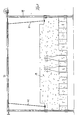
- 1 denotes the cone field of a conventional bowling alley, which next to the cone footprint with, for example, nine cones 2 shown in FIG. 3 Cone pit 3 for receiving fallen cones and an area 4 which is in front of the cone footprint lies in the fallen cone after a shot.
- This Cone field 1 is optically scanned by at least one image recording device 5 or monitored, as indicated in Fig. 1 and 2 by dash-dotted lines that the Represent the beam path from a camera 5.
- the Camera 5 can, for example, two in a row on the longitudinal axis of the cone field 1 Cameras 5 'are provided (FIG. 2), each of which is approximately half of the cone field 1 scans. Other camera positions are also possible.
- a CCD digital camera or a video camera can be used as the image recording device be provided.
- a movable image recording device for example a CCD line camera, is provided be moved over the cone field 1.
- the image processing device can also be designed in such a way that on each cone head a reflective layer or the like is provided so that the cone heads, for example can be scanned by means of a laser beam. Even in this way, an exact Position determination of a cone head can be provided for a gripper.
- Another type of image recording device consists of scanning the cones by means of of an ultrasonic sensor that records an image of the cones located on the cone field 1.
- At least one transmitter implant can be provided in each cone be scanned by means of a receiver arranged above the cone field can be. This can be used, for example, to determine the position of a cone head a transmitter implant can be provided in the cone head while determining the axis alignment another transmitter implant is provided in the lower part of the cone.
- the scanning is done by a movable recording device, preferably by line-shaped scanning in the two axial directions are predetermined by the longitudinal and transverse rails, the image data obtained being recorded and the image processing, as is the case with a camera 5 is.
- the cones present on the cone field 1 2 recorded regardless of whether they are lying or standing.
- the recorded images of the Cones are further processed in an image processing device 6 (FIG. 10), which in the Image recording device or camera 5 can be integrated or connected downstream.
- the Image processing device 6 becomes the images of the cones read by camera 5 compared with stored cone images in a comparison device 7, whereupon by a device 8 preferably determines the position of the individual optically scanned cones in such a way that approximately the center of a cone head and in the case of a lying cone, the orientation of the cone axis is also determined.
- a cone positioning device generally designated 10 controlled, individually gripped by means of the fallen cone and positioned on the cone base or can be deposited in a depot.
- the figures show a preferred embodiment of a cone erection device 10, the two longitudinal rails 11 along the two sides of the cone field 1, one slidable thereon guided cross rail 12 and a gripper slide 13 slidably guided thereon, on which a gripper that is movable in the vertical direction and rotatable about its axis 14 is performed.
- Fig. 3 15 denotes a servo motor, which, for example, toothed belt along the stationary Drives longitudinal rails 11 for moving the transverse rail 12 over the cone field 1.
- 16 with a servo motor on the gripper slide 13 is designated, which a cable drum 17th (Fig. 5) drives on which a rope 18 is wound, the ends of which are at the upper and lower End of a vertical lifting rail 19 is attached.
- a cable drum 17th (Fig. 5) drives on which a rope 18 is wound, the ends of which are at the upper and lower End of a vertical lifting rail 19 is attached.
- One is vertical on the gripper slide 13 arranged plate 20 fastened with guide rollers indicated at 21, between which the Lifting rail 19 is vertically movable.
- the electric motor 16 can thus use the cable drum 17 the gripper 14 with the lifting rail 19 in the guide on the plate 20 is raised and be lowered.
- cross rail 12 On the one side outwardly extended over the cone field 1 cross rail 12 is on Outer end of a drive motor 15 'arranged, the lifting slide 13th via toothed belt drives along the cross rail 12. The lifting carriage can thus be close to the side wall the cone field 1 are moved, as shown in FIG. 1.
- the cable drum rotatably mounted on the gripper slide 13 or on the plate 20 (FIG. 5) 17 is arranged so that at least in the lowered end position of the lifting rail 19 upper rope suspension comes to rest at the point along the rope drum where the first Cable winding lies, so that only in the raised position shown in Fig. 5, the Lifting rail 19 the rope 18 comes to lie at an angle to the rope drum 17, while in the lower End position attacks the rope 18 substantially perpendicular to the axis of the rope drum 17.
- the lifting rail 19 can be tubular, for example, with in the cavity the lifting rail 19 a rod 23 shown in Fig. 6 is rotatably guided with the gripper 14 at the lower end and a planetary gear motor 22 with built-in encoder on upper end is connected. As a result, the gripper 14 can be moved by the electric motor 22 its vertical axis can be rotated regardless of the lifting movement of the lifting rail 19th
- a gripper 14 For example, on the lifting rail 19 a frame or a pot-shaped component 25 is rotatably attached via a spring ring 24, which is fixedly connected to the rod 23 via a cross strut 26, which is in the lifting rail 19th is rotatable by the motor 22.
- a control cam 31 is rotatably supported by a drive device, For example, a magnetic motor 32 (Fig. 7) is rotatable, which is on the outside of the component 25 can be attached.
- the cam shown in Fig. 6 in the gripping position 31 can be rotated by the magnetic motor 32 into the position shown in FIG. 5 in which the spring 30 presses the gripping elements 27 into the open position.
- the gripping elements 27 which grip the head of a cone 2 are shaped such that they form a Enclose the partial surface of the cone head so that the cone 2 not only in the vertical direction, but is also fixed transversely to its longitudinal axis in the gripping position.
- the gripping elements 27 with a concave contact surface corresponding to the spherical head surface 33 provided, which is shown hatched in Fig. 7.
- the gripping elements 27 point to the lower ends each have two inwardly curved extensions 34 which the cone head on Reach behind the transition to the cone neck and thus the cone hanging in the gripper Center the position across its longitudinal axis in the gripper and hold it in the centered position.
- the first is by the Control device 9 (Fig. 10) of the electric motor 15 for moving the cross rail 12 and Electric motor 15 'for moving the gripper carriage 13 so that the gripper 14th is positioned above the center of the cone head by the camera 5 and the positioning device 8 is determined.
- the positioning device 8 is connected by the positioning device 8 with the image comparison device 7 the orientation of the longitudinal axis of the fallen Cone set, the motor 22 is controlled on the lifting rail 19 so that the gripper 14 rotates into a position in which the two gripping elements 27 on the opposite one Attack the sides of the head of the lying cone.
- the electric motor 16 of the gripper 14 After this alignment of the gripper 14 relative to the cone head is controlled by actuating the electric motor 16 of the gripper 14 lowered.
- a proximity sensor 35 is arranged in the gripper 14 and detects the approach of the gripper to the Cone head detects and at a predetermined distance of the sensor 35 relative to the cone head controls the magnetic motor 32 to rotate the cam 31. This is the Nokken 31 not completely rotated into the gripping position shown in FIG. 6 but in an intermediate position in which the two gripping elements 27 are limited by the conical neck put around the cone head, so that due to the curvature of the gripping elements 27, the cone head can be loosely gripped and raised, but the cone itself is not fixed.
- the cone detected in this way can be activated by appropriate control of the individual electric motors the cone stand field and be placed or, for example, during a Skittles are transported to a skittles depot 36, as shown in FIGS. 2, 3 and 4 is.
- the cone depot 36 is on the inside of one known, plate-shaped ball inlet lock 37 arranged along the guide rods 39 guided on both sides of the cone field 1 and can be raised via a drive motor 38 (FIG. 4) and can be lowered.
- Ball inlet lock 37 cone pockets 40 are formed, which are expediently in one Are spaced from each other, as shown in FIGS. 8 and 9.
- a cone 2 which is not required can be temporarily stored by means of the gripper 14 before after the end of a game of skittles, the cone on the cone standing surface by means of the gripper 14 is positioned.
- the ball inlet lock 37 is lowered, as shown in FIG. 8.
- the ball inlet lock 37 is over Ropes 41 connected to a shaft 42 driven by the motor 38 and acting as a rope drum, wherein the attachment of the ropes 41 on the plate 37 on one side and on the shaft 42 is designed in such a way that the cables 41 run obliquely in the lowered position, as shown in FIG. 8, while in the raised position in Fig. 9 the attachment point of the rope 41 to the plate on the Place the last turn of the rope on the shaft 42, so that in the raised position the rope 41 engages perpendicular to the plate 37.
- the rails 11 and 12 of the described cone positioning device 10 can be arranged in this way be that a cone transported by means of the gripper 14 to another location immediately is moved over the cones placed on the cone base. This results in a low overall height of the cone erection device 10.
- the overall height can additionally be reduced that the image processing device 6 including the gripper 14 controls the image data of cones still standing so that one only slightly raised by the gripper 14 Cone - as Fig. 1 shows - between the still standing cones 2 on the cone footprint is moved.
- the image data recorded by the camera 5 the standing cone 2 processed. This can be done directly in one level be worked over the cone field 1, the cone depot 36 on the same level after the ball inlet lock is always closed when the cone positioning device 10 is activated.
- a came can also be attached to the gripper 14, for example in order to grasp it to support a cone head or a cone that has fallen over when can be set up again more quickly.
- cone-setting device 10 instead of the cone-setting device 10 described, another configuration can also be used be provided, in which the cone 2 is detected by means of an image recording device 5 and transported away by a mechanism controlled by the image processing device and then be put back on the cone stand.
- the image recording device 5 only optically scan the cones located in the cone pit 3 control a gripper device which transports the cone into a cone magazine which lower the cone again by lowering it. This can also be done with a Group of cones to be worked.
- the optical monitoring of the cone field offers Different design options for the setup mechanism.
- the design according to the invention with optical monitoring of the cone field enables Adaptation to everyone by changing the program or changing a program cone stand configurations, regardless of whether it's a bowling alley, a bowling alley or other type of skittles.
- the device described can therefore be used for all types of railways and above all without further ado in existing bowling alleys can be installed instead of cable machines without extensive conversions and modifications are required.
- the optical monitoring of the cone field 1 additionally offers the possibility of the ball position with evaluating, for example by capturing images of the ball alley evaluation, Run-through evaluation and the like
- a one-armed articulated robot can also be used be provided, which grips a cone and transports it to the intended position.
- several such robot arms with grippers can be provided. It is also possible to provide several individual robots for certain tasks.
- certain automatic processes can be combined with purely mechanical processes, such as for example with the clearing of the cone stand by means of a slide, the image recording the cone takes place in the cone pit.
- an input / output device on the image processing device 6 or on the control device 9 for example in the form of keys provided to by manual input to specify a particular cone configuration by the cone erector 10 is running.
- axis calculator, servo amplifier and axis drive with incremental encoder the necessary elements are still indicated, which are necessary to carry out the individual movements are required on the cone installation device.
- AC servomotors with integrated can be used as drive motors on the cone-setting device 10
- Incremental encoders or stepper motors can be provided.
- the cone installation device can work with several CNC-controlled axes as path control.
Landscapes
- Wire Bonding (AREA)
- Control And Safety Of Cranes (AREA)
- Image Input (AREA)
- Manipulator (AREA)
Abstract
Description
- Fig. 1
- in einer schematischen Ansicht von vorne die Kegelstandfläche mit der darüber angeordneten Kegelaufstelleinrichtung,
- Fig. 2
- eine Seitenansicht der Vorrichtung nach Fig. 1,
- Fig. 3
- eine Draufsicht auf eine Vorrichtung nach den Fig. 1 und 2,
- Fig. 4
- eine Seitenansicht entsprechend Fig. 2 in einer anderen Betriebsstellung der Vorrichtung,
- Fig. 5
- eine Darstellung des Greifers mit Führung,
- Fig. 6
- eine Ansicht des Greifers in der Greifstellung an einem Kegelkopf,
- Fig. 7
- eine Seitenansicht des Greifers von Fig. 6,
- Fig. 8
- eine Ansicht des Kegelstandes von vorne mit abgesenkter Kugeleinlaufsperre,
- Fig. 9
- eine Ansicht des Kegelstandes mit angehobener Kugeleinlaufsperre, und
- Fig. 10
- ein Blockschaltbild des Verfahrensablaufs.
Claims (13)
- Verfahren zum Aufstellen von Kegeln auf einer Kegel- oder Bowlingbahn, wobei zumindest ein Teil des Kegelfeldes (1) mittels wenigstens einer Bildaufzeichnungseinrichtung (5) optisch abgetastet wird,
gefallene und/oder stehengebliebene Kegel (2) durch Bilddaten erfaßt werden,
die aufgezeichneten Bilddaten in einer Bildverarbeitungseinrichtung (6) verarbeitet und mit vorgegebenen Bilddaten verglichen werden, worauf von der Bildverarbeitungseinrichtung eine Kegelaufstelleinrichtung (10) angesteuert wird, mittels der die Kegel aufgenommen und auf dem Kegelfeld (1) oder in einem Kegeldepot (36) positioniert werden. - Verfahren nach Anspruch 1, wobei eine Steuereinrichtung (9) ein einstellbares oder auswechselbares Programm aufweist, das die Kegelaufstelleinrichtung (10) in Abhängigkeit von einem vorgegebenen Spielablauf steuert.
- Vorrichtung zum Aufstellen von Kegeln auf einer Kegel- oder Bowlingbahn, umfassend wenigstens eine über dem Kegelfeld (1) angeordnete Bildaufzeichnungseinrichtung (5), eine Bildverarbeitungseinrichtung (6) mit einem Speicher für Bilddaten und einem Steuerungsprogramm für den Spielablauf, wobei
die von der Bildverarbeitungseinrichtung der Steuerung zur Verfügung gestellten Daten eine Kegelaufstelleinrichtung (10) steuern, die die Kegel (2) faßt und an vorgegebenen Stellen auf dem Kegelfeld (1) oder in einem Kegeldepot (36) positioniert. - Vorrichtung nach Anspruch 3, wobei eine oder mehrere stationäre Kameras (5) über dem Kegelfeld (1) positioniert sind.
- Vorrichtung nach Anspruch 3, wobei wenigstens eine bewegliche Kamen über dem Kegelfeld verschiebbar und/oder verschwenkbar angeordnet ist.
- Vorrichtung nach den Ansprüchen 3 bis 5, wobei die Kegelaufstelleinrichtung (10) eine an Längsschienen (11) geführte, über das Kegelfeld (1) verschiebbare Querschiene (12) aufweist, auf der ein Greiferschlitten (13) verschiebbar ist, der einen anhebbaren und absenkbaren Greifer (14) trägt.
- Vorrichtung nach Anspruch 6, wobei der Greifer (14) um seine Hubachse verdrehbar ist.
- Vorrichtung nach Anspruch 3, wobei die Kugelaufstelleinrichtung (10) wenigstens einen einarmigen Gelenkroboter aufweist, der einen Kegel faßt, transportiert und wieder aufstellt.
- Vorrichtung nach den Ansprüchen 3 bis 8, wobei an der auf- und abbewegbaren Kugeleinlaufsperre (37) ein Kegeldepot (36)ausgebildet ist.
- Vorrichtung nach Anspruch 5 und 6, wobei am Greifer (14) oder einem beweglichen Teil (12) der Kegelaufstelleinrichtung (10) eine Kamera angebracht ist.
- Vorrichtung nach Anspruch 3, wobei die Bildaufzeichnungseinrichtung in Form eines über das Kegelfeld (1) bewegbaren Laserstrahls ausgebildet ist, der an den einzelnen Kegelköpfen angebrachte Reflexschichten oder Reflektoren abtastet.
- Vorrichtung nach Anspruch 3, wobei als Bildaufzeichnungseinrichtung ein Ultraschallsensor vorgesehen ist, der mittels Ultraschall ein Bild der auf dem Kegelfeld (1) befindlichen Kegel aufnimmt und die gewonnenen Bilddaten an die Bildverarbeitungseinrichtung weitergibt.
- Vorrichtung nach Anspruch 3, wobei die Bildaufzeichnungseinrichtung in der Weise ausgebildet ist, daß in jedem Kegel wenigstens ein Senderimplantat vorgesehen ist, das mittels eines über dem Kegelfeld (1) bewegbar angebrachten Empfängers abtastbar ist.
Applications Claiming Priority (2)
| Application Number | Priority Date | Filing Date | Title |
|---|---|---|---|
| DE1998153081 DE19853081C1 (de) | 1998-11-17 | 1998-11-17 | Verfahren und Vorrichtung zum Aufstellen von Kegeln auf einer Kegelbahn |
| DE19853081 | 1998-11-17 |
Publications (2)
| Publication Number | Publication Date |
|---|---|
| EP1002558A2 true EP1002558A2 (de) | 2000-05-24 |
| EP1002558A3 EP1002558A3 (de) | 2001-02-28 |
Family
ID=7888143
Family Applications (1)
| Application Number | Title | Priority Date | Filing Date |
|---|---|---|---|
| EP99120822A Withdrawn EP1002558A3 (de) | 1998-11-17 | 1999-10-22 | Verfahren und Vorrichtung zum Aufstellen von Kegeln auf einer Kegelbahn |
Country Status (4)
| Country | Link |
|---|---|
| EP (1) | EP1002558A3 (de) |
| DE (1) | DE19853081C1 (de) |
| HR (1) | HRP990356A2 (de) |
| PL (1) | PL336570A1 (de) |
Cited By (5)
| Publication number | Priority date | Publication date | Assignee | Title |
|---|---|---|---|---|
| NL2003002C2 (en) * | 2009-06-11 | 2010-12-15 | Securo B V | Systeem voor bowling. |
| DE102010054525A1 (de) | 2010-12-15 | 2012-04-26 | Merck Patent Gmbh | Organische Elektrolumineszenzvorrichtung |
| DE102010055902A1 (de) | 2010-12-23 | 2012-06-28 | Merck Patent Gmbh | Organische Elektrolumineszenzvorrichtung |
| WO2012149943A1 (de) | 2011-05-03 | 2012-11-08 | Novomatic Ag | Wett- und/oder spielvorrichtung |
| EP3479878A1 (de) * | 2017-11-02 | 2019-05-08 | Pin Marketing S.L. | Vorrichtung und verfahren zum aufstellen mindestens eines bowlingpins |
Family Cites Families (5)
| Publication number | Priority date | Publication date | Assignee | Title |
|---|---|---|---|---|
| US2726086A (en) * | 1949-12-28 | 1955-12-06 | American Mach & Foundry | Mechanism for arranging and spotting bowling pins |
| US3239222A (en) * | 1957-04-04 | 1966-03-08 | American Mach & Foundry | Control mechanism for disabling respotter upon either the downing of a selected pin or the rolling of a gutter ball |
| US4827412A (en) * | 1986-01-29 | 1989-05-02 | Computer Sports Systems, Inc. | Pinfall detector using video camera |
| WO1990008580A1 (fr) * | 1989-01-27 | 1990-08-09 | Kabushikikaisya Nogami Bowling Service | Installation de bowling pourvue d'un systeme de detection automatique des quilles restant debout |
| JPH07122B2 (ja) * | 1991-01-24 | 1995-01-11 | 株式会社ノガミボウリングサービス | 残ピン自動検出機能付きボウリング装置 |
-
1998
- 1998-11-17 DE DE1998153081 patent/DE19853081C1/de not_active Expired - Fee Related
-
1999
- 1999-10-22 EP EP99120822A patent/EP1002558A3/de not_active Withdrawn
- 1999-11-16 PL PL33657099A patent/PL336570A1/xx unknown
- 1999-11-17 HR HRP990356 patent/HRP990356A2/hr not_active Application Discontinuation
Cited By (14)
| Publication number | Priority date | Publication date | Assignee | Title |
|---|---|---|---|---|
| NL2003002C2 (en) * | 2009-06-11 | 2010-12-15 | Securo B V | Systeem voor bowling. |
| DE102010054525A1 (de) | 2010-12-15 | 2012-04-26 | Merck Patent Gmbh | Organische Elektrolumineszenzvorrichtung |
| DE102010055902A1 (de) | 2010-12-23 | 2012-06-28 | Merck Patent Gmbh | Organische Elektrolumineszenzvorrichtung |
| WO2012149943A1 (de) | 2011-05-03 | 2012-11-08 | Novomatic Ag | Wett- und/oder spielvorrichtung |
| CN103959349A (zh) * | 2011-05-03 | 2014-07-30 | 挪佛麦迪哥股份公司 | 游戏装置 |
| US9472053B2 (en) | 2011-05-03 | 2016-10-18 | Novomatic Ag | Gambling and/or gaming apparatus |
| US9679443B2 (en) | 2011-05-03 | 2017-06-13 | Novomatic Ag | Gambling and/or gaming apparatus |
| CN103959349B (zh) * | 2011-05-03 | 2017-11-10 | 挪佛麦迪哥股份公司 | 游戏装置 |
| EP3479878A1 (de) * | 2017-11-02 | 2019-05-08 | Pin Marketing S.L. | Vorrichtung und verfahren zum aufstellen mindestens eines bowlingpins |
| WO2019086150A1 (de) * | 2017-11-02 | 2019-05-09 | Pin Marketing Sl | Vorrichtung und verfahren zum aufstellen mindestens eines bowlingpins |
| JP2021502204A (ja) * | 2017-11-02 | 2021-01-28 | ピン マーケティング エセエレ | 少なくとも1つのボウリングピンを配置するための装置及び方法 |
| EP3831453A1 (de) * | 2017-11-02 | 2021-06-09 | Pin Marketing S.L. | Vorrichtung und verfahren zum aufstellen mindestens eines bowlingpins |
| JP7025065B2 (ja) | 2017-11-02 | 2022-02-24 | ピン マーケティング エセエレ | 少なくとも1つのボウリングピンを配置するための装置及び方法 |
| US11266902B2 (en) | 2017-11-02 | 2022-03-08 | Pin Marketing Sl | Robotic device and method for setting up at least one bowling pin |
Also Published As
| Publication number | Publication date |
|---|---|
| EP1002558A3 (de) | 2001-02-28 |
| PL336570A1 (en) | 2000-05-22 |
| HRP990356A2 (en) | 2000-12-31 |
| DE19853081C1 (de) | 2000-07-27 |
Similar Documents
| Publication | Publication Date | Title |
|---|---|---|
| DE2946616A1 (de) | Vorrichtung zum ausrichten von werkstuecken | |
| DE60313526T3 (de) | Verfahren und Vorrichtung zum automatischen Zuführen von stabförmigen Metallprofilen in Profilbearbeitungsmaschinen | |
| DE3744987C2 (de) | ||
| DE3542496A1 (de) | Verfahren und vorrichtung zum zufuehren von montageteilen | |
| DE3500949A1 (de) | Verfahren und vorrichtung zum herstellen von verlitztem stranggut mit hilfe einer doppelschlagverlitzmaschine | |
| DE1201245B (de) | Vorrichtung zum Foerdern eines Werkstueckes | |
| DE69402284T2 (de) | Vorrichtung zum Verarbeiten von Stangen insbesondere Stangen für Stahlbeton | |
| DE19853081C1 (de) | Verfahren und Vorrichtung zum Aufstellen von Kegeln auf einer Kegelbahn | |
| DE3921350C1 (de) | ||
| DE19724635C2 (de) | Werkzeugmaschine mit Werkzeugauswechselvorrichtung | |
| EP0032656A2 (de) | Anlage zum Herstellen von Bügeln verschiedener Gestalt und Grösse, insbesondere von Betonbewehrungsbügeln | |
| EP0860259A2 (de) | Vorrichtung für den Transport von Substraten | |
| DE60205552T2 (de) | Linearer Verschliesser und Verschlussmethode | |
| DE3410656C2 (de) | ||
| EP1366834A1 (de) | Werkzeugwechselvorrichtung für Pressen | |
| DE4124356C1 (en) | Pipe bending machine with clamping head on frame - which forms support column with top cantilever arm whose free end forms bearing for rotary head | |
| DE69129077T2 (de) | Verfahren und vorrichtung zum schneiden von rohren, in welchem die rohre mittels einer rotierenden festhaltplatte in schneidposition gebracht werden | |
| DE10104355A1 (de) | Vorrichtung und Verfahren zur Bildabtastung der Oberfläche eines Objekts | |
| DE19909478C2 (de) | Vorrichtung zum Härten von Teilen | |
| EP0901874A2 (de) | Vorrichtung zum Bearbeiten rohrförmiger Körper mittels eines Laserstrahles | |
| DE4431389C1 (de) | Verfahren und Vorrichtung zum Setzen von Stopfen an Stopfenwalzwerken | |
| EP0509972B1 (de) | Ladevorrichtung für Zapfenschneidemaschinen und ähnliche Maschinen | |
| DE3121237A1 (de) | Vorrichtung zum ergreifen und transportieren plattenfoermiger gegenstaende | |
| DE102017114873B4 (de) | Verfahren und Vorrichtung zum dreidimensionalen Erfassen einer dreidimensionalen Oberfläche eines Werkstücks | |
| EP0857524A2 (de) | Drahtbund-Bildestation |
Legal Events
| Date | Code | Title | Description |
|---|---|---|---|
| PUAI | Public reference made under article 153(3) epc to a published international application that has entered the european phase |
Free format text: ORIGINAL CODE: 0009012 |
|
| AK | Designated contracting states |
Kind code of ref document: A2 Designated state(s): AT BE CH CY DE DK ES FI FR GB GR IE IT LI LU MC NL PT SE |
|
| AX | Request for extension of the european patent |
Free format text: AL;LT;LV;MK;RO PAYMENT 19991022;SI PAYMENT 19991022 |
|
| PUAL | Search report despatched |
Free format text: ORIGINAL CODE: 0009013 |
|
| AK | Designated contracting states |
Kind code of ref document: A3 Designated state(s): AT BE CH CY DE DK ES FI FR GB GR IE IT LI LU MC NL PT SE |
|
| AX | Request for extension of the european patent |
Free format text: AL;LT;LV;MK;RO PAYMENT 19991022;SI PAYMENT 19991022 |
|
| 17P | Request for examination filed |
Effective date: 20010420 |
|
| AKX | Designation fees paid |
Free format text: AT BE CH CY DE DK ES FI FR GB GR IE IT LI LU MC NL PT SE |
|
| AXX | Extension fees paid |
Free format text: RO PAYMENT 19991022;SI PAYMENT 19991022 |
|
| GRAP | Despatch of communication of intention to grant a patent |
Free format text: ORIGINAL CODE: EPIDOSNIGR1 |
|
| STAA | Information on the status of an ep patent application or granted ep patent |
Free format text: STATUS: THE APPLICATION IS DEEMED TO BE WITHDRAWN |
|
| 18D | Application deemed to be withdrawn |
Effective date: 20040429 |