EP1002592B1 - Machine de cintrage de fil, en particulier pour cintrer des fers pour béton armé - Google Patents
Machine de cintrage de fil, en particulier pour cintrer des fers pour béton armé Download PDFInfo
- Publication number
- EP1002592B1 EP1002592B1 EP99890358A EP99890358A EP1002592B1 EP 1002592 B1 EP1002592 B1 EP 1002592B1 EP 99890358 A EP99890358 A EP 99890358A EP 99890358 A EP99890358 A EP 99890358A EP 1002592 B1 EP1002592 B1 EP 1002592B1
- Authority
- EP
- European Patent Office
- Prior art keywords
- bending
- wire
- mandrel
- mandrels
- plane
- Prior art date
- Legal status (The legal status is an assumption and is not a legal conclusion. Google has not performed a legal analysis and makes no representation as to the accuracy of the status listed.)
- Expired - Lifetime
Links
- 238000005452 bending Methods 0.000 title claims abstract description 194
- 229910000831 Steel Inorganic materials 0.000 title abstract 2
- 239000010959 steel Substances 0.000 title abstract 2
- 230000003014 reinforcing effect Effects 0.000 title 1
- 238000003780 insertion Methods 0.000 claims description 25
- 230000037431 insertion Effects 0.000 claims description 25
- 230000033001 locomotion Effects 0.000 claims description 9
- 230000001681 protective effect Effects 0.000 claims description 6
- 230000003247 decreasing effect Effects 0.000 claims description 3
- 229910000746 Structural steel Inorganic materials 0.000 claims description 2
- 238000000034 method Methods 0.000 description 7
- 238000006243 chemical reaction Methods 0.000 description 1
- 230000000694 effects Effects 0.000 description 1
- 238000005096 rolling process Methods 0.000 description 1
Images

Classifications
-
- B—PERFORMING OPERATIONS; TRANSPORTING
- B21—MECHANICAL METAL-WORKING WITHOUT ESSENTIALLY REMOVING MATERIAL; PUNCHING METAL
- B21F—WORKING OR PROCESSING OF METAL WIRE
- B21F1/00—Bending wire other than coiling; Straightening wire
- B21F1/02—Straightening
-
- B—PERFORMING OPERATIONS; TRANSPORTING
- B21—MECHANICAL METAL-WORKING WITHOUT ESSENTIALLY REMOVING MATERIAL; PUNCHING METAL
- B21D—WORKING OR PROCESSING OF SHEET METAL OR METAL TUBES, RODS OR PROFILES WITHOUT ESSENTIALLY REMOVING MATERIAL; PUNCHING METAL
- B21D11/00—Bending not restricted to forms of material mentioned in only one of groups B21D5/00, B21D7/00, B21D9/00; Bending not provided for in groups B21D5/00 - B21D9/00; Twisting
- B21D11/10—Bending specially adapted to produce specific articles, e.g. leaf springs
- B21D11/12—Bending specially adapted to produce specific articles, e.g. leaf springs the articles being reinforcements for concrete
Definitions
- the invention relates to a wire bending machine, in particular for Bending structural steel wires, with one or two longitudinally movable, one bending head receiving bending slide, the bending head two towering, between a longitudinally aligned insertion gap for insertion a bending mandrel to release a piece of wire to be bent as well as on the Bending end of the wire piece facing side of the mandrels one by one parallel pivot axis running in the area of the insertion gap swivel-adjustable bending arm with one in the same direction as the bending mandrels towering bending pin and on the mandrel side facing away from the bending end a wire clamp with two jaws that can be moved transversely to the splitting direction having.
- the bending radius to be selected is the Wire pieces depends on the respective wire diameter and this bending radius is determined by the diameter of the mandrel, can be based on the known Wire bending machines with one and the same bending tools only ever wire pieces a certain diameter range adapted to the respective mandrel diameter bend and the bending of wire pieces accordingly different Diameter ranges requires a conversion of the bending machine suitable bending tools.
- the invention is therefore based on the object of a wire bending machine to create the kind of bending of wires of different kinds Allowed wire diameter with constant bending tools and is also characterized by its diverse bending options.
- the invention solves this problem in the generic wire bending machine in that the two mandrels each at least two arranged symmetrically to the longitudinal center plane of the insertion gap, radially offset against each other towards the insertion gap and a common, mandrel sections defining the insertion gap defining the tangential plane different, decreasing from the mandrel section to the mandrel section Diameter include that preferably also the bending pin the same pin sections in number, height and diameter forms, whose axially offset axes in a common Axial plane through the pivot axis of the bending arm and their radial distances from the swivel axis, the dimension of half the insertion gap enlarged section diameter exceeds, the bending mandrels and optionally the swivel arm with the bending pin in the axial direction compared to an axis normal given by a support for the wire pieces Bending plane height-adjustable according to the mandrel sections are, and that the wire clamp from an open position with the
- the mandrels opposite the bending plane can the mandrels on each to be matched to bending diameter ranges by the for these diameter ranges match mandrel sections in a compared to the Bending level can be brought to the correct height.
- the pieces of wire can then be bent with a suitable bending radius, the adjustment of the bending mandrels to the respective wire diameter every bending process by simply selecting the appropriate mandrel sections and corresponding stroke adjustment and therefore different pieces of wire can also be bent correctly in any order in succession.
- the wire clamp by selectively applying one or the other Clamp not only for actually clamping the wire pieces, but also used to place the wire pieces on the mandrel to be used, so that even with small wire diameters compared to the insertion gap proper bending to one side or the other.
- a bending pin gradation corresponding to the mandrel gradation in Pin sections which are not absolutely necessary in normal bending processes would be the bending process, especially when bending by more than 90 ° improved because of the rolling movement of the corresponding pin sections at the bending end of the piece of wire, smaller relative movements between Pin portion and piece of wire occur and so a risk of damage Wire surface must be prevented.
- the slide drives, the drives for the swivel arms, the lifting drives for the mandrels and swivel arms and bending pins and especially the wire clamps can be controlled individually be what but with a corresponding control device without Difficulties is possible.
- the bending head has an additional bending stop on the bending mandrel on the outside of the movement path of the bending pin with a lateral offset is arranged opposite the tangential planes of the mandrels itself with a swiveling movement of the swivel arm with its bending end both on the associated mandrel and on the bending stop
- the lateral offset of the bending stop compared to the mandrel specifies the distance between the Z-legs.
- the bending stop can be raised from a basic position to a bending position supported, this bending stop can be used optionally, then without in the basic position the end of the wire piece moving during bending to be.
- the bending head on the bending slide is vertical Is inclined and defines a longitudinally inclined bending plane
- the bending slide a cover with a recess for the Bending head and a support for the wire pieces, which cover a starting position parallel to the bending plane can be folded up into a drop position is stored.
- the bending plane makes it easier to insert the wire pieces for the bending process and then after the bending process, bringing out the bent pieces of wire, for which it is sufficient to place the wire pieces in the insertion gap when the cover is folded down let it fall or the cover in its original position is below the bending level to fold up, so that when folding up bent wire piece with the support when the wire clamp is open again be lifted out of the insertion gap and thrown out of the machine can.
- the piece of wire then falls into a gutter along a sliding path or the like .
- the cover is with a sliding Protective shield to close the recess, so that after the With the wire clamp still closed, bend the bending head down out of the Extends recess and the protective shield closes the recess, whereby with the following ejection, the wire pieces can no longer get caught is.
- the cover has an edge strip with a runway for one to be bent End of the piece of wire becomes the end of the piece of wire when bent by more than 90 ° raised by the run-up to the run-up track from the bending plane, so that closed bending forms are also possible with a correspondingly multiple bending allow to reach, whereby then the two bending ends lie on top of each other come.
- the bending head has lifting rods that can be raised are arranged along the tangential plane of the lower mandrel.
- This Catch rods make it easy to bend the wire rods from above to drop the feeder device provided for the bending machine and they into the insertion gap via the catching rods raised to the catching position or to insert the open wire clamp.
- the feeder device is advantageously with the one directly to the straightening and cutting device Wire straightener connected to wire outlet in which the wire pieces also positioned via appropriate directional stops for further processing Service Provider.
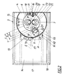
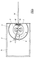
- a wire bending machine 1 has a machine frame 2 with two longitudinally movable Bending slide 3, each bending slide 3 having a bending head 4 two towering, one longitudinally aligned insertion gap between them 5 for the insertion of a piece of wire W to be left free bending mandrels 6, 7 and one around a mandrel parallel, in the area of the insertion gap 5 running swivel axis S swivel-adjustable bending arm 8 velvet one in the same direction as the bending mandrels 6, 7 towering bending pin 9 and a wire clamp 10 from two jaws movable transversely to the splitting direction 11, 12 records.
- the bending mandrels 6, 7 form three to the longitudinal center plane E of the insertion gap 5 symmetrically arranged mandrel sections 61, 62, 63; 71, 72, 73 different, upwards from mandrel section to mandrel section of decreasing diameter D1, D2, D3, which are radially offset from one another towards the insertion gap 5 are and in each case a common tangential plane delimiting the insertion gap 5 Determine T6, T7.
- the bending pin 9 also has three pin sections 91, 92, 93, which are adapted in their dimensions to the mandrel sections and their axially offset axes in a common axial plane A lie through the pivot axis S and their radial distances a, b, c from of the swivel axis S is increased by half the insertion gap width Section diameter exceeds D1, D2, D3.
- the bending mandrels 6, 7 and the swivel arm 8 with its bending pin 9 are opposite in the axial direction the bending plane B height adjustable, so that for bending the wire pieces depending on the wire diameter, one or the other Mandrel and tenon sections can be used.
- the wire clamp 10 is in the open position with its jaws 11, 12 on the Tangential planes T6, T7 aligned and can optionally be operated of one or the other jaw 11, 12 close, so that when using the one or the other mandrel 6, 7 the wire when clamping to the respective mandrel is created by closing the clamp accordingly.
- the bending head 4 has an additional bending stop on the bending mandrel 6, 7 13 on the outside of the path of movement of the bending pin 9 with lateral offset V is arranged opposite to the tangential planes T6, T7 a lowered basic position into a bending position protruding into the bending area can be raised.
- the bending head 4 is inclined on the bending slide 3 to a vertical longitudinal plane and determines a longitudinally inclined bending plane B, the bending slide 3 is equipped with a cover 14 which has a recess 15 for has the bending head 4 and a support 16 for the wire rods to be bent forms.
- the cover 14 is also arranged with a cross-slide Protective shield 17 provided, that with lowered mandrels or bending pins close the recess 15 except for the area around the wire clamp 10 can.
- the cover 14 of one of the bending slides carries one in the lower edge area Edge strip 18 with a run-up track for a wire piece end to be bent, so that this is lifted out of the bending plane when bending through larger angles and is bent transversely and bending a closed bow shape with side by side Wire ends is made possible.
- Retractable catch rods 19, 20 are also provided on the bending head 4 are arranged along the tangential plane T7 of the lower mandrel 7 and facilitate the insertion of the wire rods to be bent into the insertion gap 5 should.
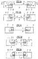
- the jaws 11, 12 of the wire clamps 10 are open and the interception rods 19, 20, as indicated by dashed lines in FIG. 1, raised so that the piece of wire falling off the ejector slides along the catch rods and both in the insertion gaps 5 and also come to rest in the correct position in the open wire clamps 10 (Fig. 3a).
- the lower ones Jaws 12 actuated and the wire piece W against the upper standing Clamping jaws 11 clamped so that the piece of wire also on the upper mandrels 6 is present.
- the bending heads 4 can be used in a simple manner with the help of the raised bending stop 13 into the bending position Z-bend can be achieved, for which purpose only to clamp the inserted wire piece W. and by means of a corresponding swiveling movement of the swivel arm 8 of the bending pin 9 between the corresponding mandrel 6 and the Bending stop 13 is to be used.
Landscapes
- Engineering & Computer Science (AREA)
- Mechanical Engineering (AREA)
- Wire Processing (AREA)
- Bending Of Plates, Rods, And Pipes (AREA)
Claims (7)
- Machine de cintrage de fil (1), en particulier pour cintrer des fers pour béton armé, avec un ou deux chariots de cintrage (3) déplaçables longitudinalement, supportant une tête de cintrage (4), la tête de cintrage (4) présentant deux mandrins de cintrage (6, 7) en saillie, laissant libre entre eux un intervalle d'insertion (5) orienté en direction longitudinale, pour insérer un tronçon de fil (W) à cintrer, ainsi que présentant, sur le côté, tourné vers l'extrémité à cintrer du tronçon de fil (W), des mandrins de cintrage (6, 7), un bras de cintrage (8), susceptible d'être manoeuvré par pivotement autour d'un axe de pivotement (S) parallèle à l'axe de mandrin, s'étendant dans la zone de l'intervalle d'insertion (5), le bras de cintrage (8) présentant un tourillon de cintrage (9), en saillie dans le même sens vers les mandrins de cintrage (6, 7) et, sur le côté de mandrin de cintrage tourné vers l'extrémité à cintrer, présentant une pince à fil (10) munie de deux mâchoires de serrage (11, 12) déplaçables transversalement à la direction d'intervalle, caractérisée en ce que les deux mandrins de cintrage (6, 7) comprennent chacun deux tronçons de mandrin (61, 62, 63; 71, 72, 73), disposés symétriquement par rapport à l'axe médian longitudinal (E) de l'intervalle d'insertion (5) et décalés l'un par rapport à l'autre radialement par rapport à l'intervalle d'insertion et déterminant un plan tangentiel (T6, T7) commun, délimitant l'intervalle d'insertion, les tronçons de mandrin ayant des diamètres (D1, D2, D3) différents, allant en diminuant en direction du haut, d'un tronçon de mandrin à un autre tronçon de mandrin, de manière que, de préférence également, le tourillon de cintrage (9) forme des tronçons de tourillon (91, 92, 93) identiques aux tronçons de mandrin, quant au nombre, hauteur et diamètre, tronçons de tourillon dont les axes, décalés radialement les uns par rapport aux autres, sont situés dans un plan axial (A) commun, passant par l'axe de pivotement (S) du bras de cintrage (8), et dont les espacements radiaux (a, b, c) par rapport à l'axe de pivotement (S) dépassent chaque fois la valeur du diamètre de tronçon (D1, D2, D3), augmenté de la moitié de la largeur d'intervalle d'insertion, les mandrins de cintrage (6, 7) et, le cas échéant, le bras pivotant (8) avec le tourillon de cintrage (9), étant montés de façon à être réglables en hauteur, de manière correspondant aux tronçons de mandrin, en direction axiale par rapport à un plan de cintrage (B) perpendiculaire à l'axe prédéterminé par un reposoir (16) pour les tronçons de fil (W), et en ce que la pince à fil (10) est susceptible d'être actionnée depuis une position ouverte, à laquelle les mâchoires de serrage (11, 12) sont orientées sur les plans tangentiels (T6, T7) des tronçons de mandrin, en fonction du cintrage effectué chaque fois autour de l'un ou l'autre mandrin de cintrage (6, 7), par un déplacement transversal, effectué au choix, de la mâchoire de serrage chaque fois opposée à ce mandrin de cintrage.
- Machine de cintrage de fil selon la revendication 1, caractérisée en ce que la tête de cintrage (4) présente, côté cintrage des mandrins de cintrage (6, 7), une butée de cintrage (13) supplémentaire disposée à l'extérieur de la trajectoire de déplacement du tourillon de cintrage (9), avec un décalage latéral (V) par rapport aux plans tangentiels (T6, T7) des mandrins de cintrage (6, 7).
- Machine de cintrage de fil selon la revendication 2, caractérisée en ce que la butée de cintrage (3) est soutenue de façon à être relevable de la position de base à une position de cintrage.
- Machine de cintrage de fil selon l'une des revendications 1 à 3, caractérisée en ce que la tête de cintrage (4) est placée obliquement par rapport à un plan longitudinal vertical, sur le chariot de cintrage (3), et détermine un plan de cintrage (B) incliné en direction longitudinale, le chariot de cintrage (3) présentant un recouvrement (14) avec un évidement (15) pour la tête de cintrage (4) et un reposoir (16) pour les tronçons de fil (W), ledit recouvrement (14) étant monté de façon à pouvoir être relevé par rabattement d'une position initiale, parallèle au plan de cintrage (B), à une position d'éjection.
- Machine de cintrage de fil selon la revendication 4, caractérisée en ce que le recouvrement (14) est muni d'un bouclier de protection (17) déplaçable, dans le but de fermer l'évidement (15).
- Machine de cintrage de fil selon la revendication 4 ou 5, caractérisée en ce que le recouvrement (14) présente une bande de bordure (18) avec une piste de franchissement (19), pour une extrémité de tronçon de fil à cintrer.
- Machine de cintrage de fil selon l'une des revendications 4 à 6, caractérisée en ce que la tête de cintrage (4) présente des barres d'emprisonnement (20) relevables, disposées le long du plan tangentiel (T7) du mandrin de cintrage inférieur (7).
Applications Claiming Priority (2)
| Application Number | Priority Date | Filing Date | Title |
|---|---|---|---|
| AT193798 | 1998-11-20 | ||
| AT0193798A AT406744B (de) | 1998-11-20 | 1998-11-20 | Drahtbiegemaschine, insbesondere zum biegen von baustahldrähten |
Publications (3)
| Publication Number | Publication Date |
|---|---|
| EP1002592A2 EP1002592A2 (fr) | 2000-05-24 |
| EP1002592A3 EP1002592A3 (fr) | 2001-12-12 |
| EP1002592B1 true EP1002592B1 (fr) | 2003-03-19 |
Family
ID=3524255
Family Applications (1)
| Application Number | Title | Priority Date | Filing Date |
|---|---|---|---|
| EP99890358A Expired - Lifetime EP1002592B1 (fr) | 1998-11-20 | 1999-11-09 | Machine de cintrage de fil, en particulier pour cintrer des fers pour béton armé |
Country Status (3)
| Country | Link |
|---|---|
| EP (1) | EP1002592B1 (fr) |
| AT (2) | AT406744B (fr) |
| DE (1) | DE59904609D1 (fr) |
Families Citing this family (12)
| Publication number | Priority date | Publication date | Assignee | Title |
|---|---|---|---|---|
| DK176637B1 (da) * | 2003-12-24 | 2009-01-05 | Stema Engineering As | Fremgangsmåde ved bukning af stangmateriale samt værktöj til udövelse heraf |
| CN102416569B (zh) * | 2011-09-29 | 2013-07-17 | 宁波新州焊接设备有限公司 | 钢筋桁架成型机上的钢筋夹紧机构 |
| CN104526446B (zh) * | 2014-12-24 | 2017-02-22 | 宁波沃特美逊机器人科技有限公司 | 一种单向夹紧定位机构 |
| CN108372256A (zh) * | 2018-04-11 | 2018-08-07 | 马鞍山启元自动化技术有限责任公司 | 一种钢筋弯曲机及其使用方法 |
| CN109473844B (zh) * | 2018-07-18 | 2020-02-21 | 国网浙江嘉善县供电有限公司 | 一种钢绞线装配制作机 |
| CN110625031B (zh) * | 2019-10-10 | 2024-07-30 | 山西省安装集团股份有限公司 | 对不同粗细钢筋任意曲率和角度加工的弯箍机及使用方法 |
| AT523405B1 (de) | 2020-03-03 | 2021-08-15 | Progress Maschinen & Automation Ag | Biegekopf für Baustahlmatten |
| IT202100030896A1 (it) * | 2021-12-07 | 2023-06-07 | M E P Macch Elettroniche Piegatrici Spa | Apparato e procedimento per la piegatura di prodotti metallici oblunghi |
| CN115055560B (zh) * | 2022-07-11 | 2025-11-28 | 宝银特材科技股份有限公司 | 一种螺旋管旋压装置及高精度螺旋管制造方法 |
| CN116786710B (zh) * | 2023-07-28 | 2026-01-30 | 廊坊凯博建设机械科技有限公司 | 一种双向弯曲和自动变径的大型钢筋制品弯曲成型设备 |
| CN117840279B (zh) * | 2024-03-05 | 2024-04-30 | 山东霖臻睿空调设备有限公司 | 一种空调风机盘管组件自动成型设备 |
| CN118925895B (zh) * | 2024-07-24 | 2025-03-18 | 山东东能建设服务有限公司 | 一种建筑工程用建筑垃圾破碎装置 |
Family Cites Families (2)
| Publication number | Priority date | Publication date | Assignee | Title |
|---|---|---|---|---|
| DE3546448A1 (de) * | 1985-03-12 | 1986-09-25 | Alpha Maschinenbau AG, Zürich | Biegevorrichtung |
| DE4443518A1 (de) * | 1994-12-07 | 1996-06-13 | Peddinghaus Carl Ullrich Dr | Verfahren zum Biegen von Stahlstäben, insbesondere zum Biegen von Betonstahlstäben zu Bewehrungsbügeln |
-
1998
- 1998-11-20 AT AT0193798A patent/AT406744B/de not_active IP Right Cessation
-
1999
- 1999-11-09 DE DE59904609T patent/DE59904609D1/de not_active Expired - Fee Related
- 1999-11-09 AT AT99890358T patent/ATE234694T1/de not_active IP Right Cessation
- 1999-11-09 EP EP99890358A patent/EP1002592B1/fr not_active Expired - Lifetime
Also Published As
| Publication number | Publication date |
|---|---|
| ATE234694T1 (de) | 2003-04-15 |
| EP1002592A2 (fr) | 2000-05-24 |
| DE59904609D1 (de) | 2003-04-24 |
| ATA193798A (de) | 2000-01-15 |
| AT406744B (de) | 2000-08-25 |
| EP1002592A3 (fr) | 2001-12-12 |
Similar Documents
| Publication | Publication Date | Title |
|---|---|---|
| DE2822476C2 (de) | Einrichtung zum Schneiden länglichen Profilmaterials, insbesondere von Rohrmaterial | |
| DE2704540C2 (fr) | ||
| DE3346523C2 (de) | Vorrichtung zum Zusammenbau eines Kraftfahrzeug-Körpers | |
| DE2649765C2 (fr) | ||
| AT406744B (de) | Drahtbiegemaschine, insbesondere zum biegen von baustahldrähten | |
| AT401360B (de) | Biegeanlage für stäbe | |
| EP0446702A2 (fr) | Dispositif pour enlever des pièces tranchées d'un matérial plié ou similaires | |
| DE3042871A1 (de) | Maschine zum formen von werkstuecken | |
| EP0602308A1 (fr) | Dispositif pour travailler les côtés de pièces en forme de plaques alimentées de façon continue | |
| DE1615052A1 (de) | Maschine zur Herstellung von Drahtanschluessen | |
| WO1993001904A1 (fr) | Machine pour la confection de treillis constitues de fils metalliques longitudinaux et transversaux soudes ensemble | |
| DE2843531C2 (de) | Maschine zum Herstellen von gitterträgerartigen Bewehrungsgebilden für Stahlbeton | |
| DE19642930A1 (de) | Vorrichtung zum Biegen oder Krümmen von Hohlprofilleisten | |
| DE3314766C2 (de) | Ausziehtisch | |
| DE2624169B2 (de) | Vorrichtung und verfahren zum kontinuierlichen aufwickeln eines drahtes | |
| DE2920059A1 (de) | Vorrichtung zum biegen, sicken und ablaengen der anschlussdraehte von elektrischen bauelementen | |
| DE2910633C2 (fr) | ||
| AT520649B1 (de) | Verfahren mit einer Fertigungseinrichtung zum Umformen von Blech | |
| EP1427552B1 (fr) | Dispositif pour deformer un materiau a faible epaisseur de paroi de facon a creer un corps en forme de douille | |
| EP0659538B1 (fr) | Dispositif pour placer des anses sur des récipients | |
| DE19624584C1 (de) | Verfahren und Vorrichtung zum Zerschneiden eines Tonstrangs | |
| DE2420866A1 (de) | Vorrichtung zum trimmen und/oder unterteilen eines drahtwindungsstranges in einer bundbildestation | |
| DE69429921T2 (de) | Werkstückpressvorrichtung für variablen Aufbau mit vorbestimmten Schritten für Abkantpressen | |
| DE102020107192B3 (de) | Vorrichtung zum Biegen mindestens eines in einem Ausgangszustand U-förmigen Leiterstücks und ein entsprechendes Verfahren | |
| DE3109110A1 (de) | Vorrichtung zur bildung von walzdrahtbunden |
Legal Events
| Date | Code | Title | Description |
|---|---|---|---|
| PUAI | Public reference made under article 153(3) epc to a published international application that has entered the european phase |
Free format text: ORIGINAL CODE: 0009012 |
|
| AK | Designated contracting states |
Kind code of ref document: A2 Designated state(s): AT BE CH CY DE DK ES FI FR GB GR IE IT LI LU MC NL PT SE Kind code of ref document: A2 Designated state(s): AT DE |
|
| AX | Request for extension of the european patent |
Free format text: AL;LT;LV;MK;RO;SI |
|
| PUAL | Search report despatched |
Free format text: ORIGINAL CODE: 0009013 |
|
| AK | Designated contracting states |
Kind code of ref document: A3 Designated state(s): AT BE CH CY DE DK ES FI FR GB GR IE IT LI LU MC NL PT SE |
|
| AX | Request for extension of the european patent |
Free format text: AL;LT;LV;MK;RO;SI |
|
| RIC1 | Information provided on ipc code assigned before grant |
Free format text: 7B 21D 11/12 A, 7B 21F 1/00 B, 7B 21D 7/022 B |
|
| 17P | Request for examination filed |
Effective date: 20020517 |
|
| GRAH | Despatch of communication of intention to grant a patent |
Free format text: ORIGINAL CODE: EPIDOS IGRA |
|
| AKX | Designation fees paid |
Free format text: AT DE |
|
| GRAH | Despatch of communication of intention to grant a patent |
Free format text: ORIGINAL CODE: EPIDOS IGRA |
|
| GRAA | (expected) grant |
Free format text: ORIGINAL CODE: 0009210 |
|
| AK | Designated contracting states |
Designated state(s): AT DE |
|
| REG | Reference to a national code |
Ref country code: IE Ref legal event code: FG4D Free format text: GERMAN |
|
| REF | Corresponds to: |
Ref document number: 59904609 Country of ref document: DE Date of ref document: 20030424 Kind code of ref document: P |
|
| REG | Reference to a national code |
Ref country code: IE Ref legal event code: FD4D Ref document number: 1002592E Country of ref document: IE |
|
| PLBE | No opposition filed within time limit |
Free format text: ORIGINAL CODE: 0009261 |
|
| STAA | Information on the status of an ep patent application or granted ep patent |
Free format text: STATUS: NO OPPOSITION FILED WITHIN TIME LIMIT |
|
| 26N | No opposition filed |
Effective date: 20031222 |
|
| PGFP | Annual fee paid to national office [announced via postgrant information from national office to epo] |
Ref country code: AT Payment date: 20081128 Year of fee payment: 10 |
|
| PGFP | Annual fee paid to national office [announced via postgrant information from national office to epo] |
Ref country code: DE Payment date: 20090130 Year of fee payment: 10 |
|
| PG25 | Lapsed in a contracting state [announced via postgrant information from national office to epo] |
Ref country code: AT Free format text: LAPSE BECAUSE OF NON-PAYMENT OF DUE FEES Effective date: 20091109 |
|
| PG25 | Lapsed in a contracting state [announced via postgrant information from national office to epo] |
Ref country code: DE Free format text: LAPSE BECAUSE OF NON-PAYMENT OF DUE FEES Effective date: 20100601 |