EP1002622A2 - Dispositif pour le support d'une pièce en forme de barre sur une machine d'usinage - Google Patents
Dispositif pour le support d'une pièce en forme de barre sur une machine d'usinage Download PDFInfo
- Publication number
- EP1002622A2 EP1002622A2 EP99122603A EP99122603A EP1002622A2 EP 1002622 A2 EP1002622 A2 EP 1002622A2 EP 99122603 A EP99122603 A EP 99122603A EP 99122603 A EP99122603 A EP 99122603A EP 1002622 A2 EP1002622 A2 EP 1002622A2
- Authority
- EP
- European Patent Office
- Prior art keywords
- workpiece
- support body
- rotation
- radius
- support device
- Prior art date
- Legal status (The legal status is an assumption and is not a legal conclusion. Google has not performed a legal analysis and makes no representation as to the accuracy of the status listed.)
- Granted
Links
- 239000002184 metal Substances 0.000 claims description 3
- 238000003754 machining Methods 0.000 description 7
- 238000003698 laser cutting Methods 0.000 description 5
- 238000007599 discharging Methods 0.000 description 2
- 238000000034 method Methods 0.000 description 2
- 230000002093 peripheral effect Effects 0.000 description 2
- 230000015572 biosynthetic process Effects 0.000 description 1
- 238000010276 construction Methods 0.000 description 1
- 238000006073 displacement reaction Methods 0.000 description 1
- 230000000694 effects Effects 0.000 description 1
- 238000007665 sagging Methods 0.000 description 1
Images


Classifications
-
- B—PERFORMING OPERATIONS; TRANSPORTING
- B23—MACHINE TOOLS; METAL-WORKING NOT OTHERWISE PROVIDED FOR
- B23K—SOLDERING OR UNSOLDERING; WELDING; CLADDING OR PLATING BY SOLDERING OR WELDING; CUTTING BY APPLYING HEAT LOCALLY, e.g. FLAME CUTTING; WORKING BY LASER BEAM
- B23K26/00—Working by laser beam, e.g. welding, cutting or boring
- B23K26/08—Devices involving relative movement between laser beam and workpiece
- B23K26/0823—Devices involving rotation of the workpiece
-
- B—PERFORMING OPERATIONS; TRANSPORTING
- B23—MACHINE TOOLS; METAL-WORKING NOT OTHERWISE PROVIDED FOR
- B23K—SOLDERING OR UNSOLDERING; WELDING; CLADDING OR PLATING BY SOLDERING OR WELDING; CUTTING BY APPLYING HEAT LOCALLY, e.g. FLAME CUTTING; WORKING BY LASER BEAM
- B23K26/00—Working by laser beam, e.g. welding, cutting or boring
- B23K26/08—Devices involving relative movement between laser beam and workpiece
- B23K26/083—Devices involving movement of the workpiece in at least one axial direction
- B23K26/0838—Devices involving movement of the workpiece in at least one axial direction by using an endless conveyor belt
- B23K26/0846—Devices involving movement of the workpiece in at least one axial direction by using an endless conveyor belt for moving elongated workpieces longitudinally, e.g. wire or strip material
-
- B—PERFORMING OPERATIONS; TRANSPORTING
- B23—MACHINE TOOLS; METAL-WORKING NOT OTHERWISE PROVIDED FOR
- B23Q—DETAILS, COMPONENTS, OR ACCESSORIES FOR MACHINE TOOLS, e.g. ARRANGEMENTS FOR COPYING OR CONTROLLING; MACHINE TOOLS IN GENERAL CHARACTERISED BY THE CONSTRUCTION OF PARTICULAR DETAILS OR COMPONENTS; COMBINATIONS OR ASSOCIATIONS OF METAL-WORKING MACHINES, NOT DIRECTED TO A PARTICULAR RESULT
- B23Q1/00—Members which are comprised in the general build-up of a form of machine, particularly relatively large fixed members
- B23Q1/72—Auxiliary arrangements; Interconnections between auxiliary tables and movable machine elements
- B23Q1/76—Steadies; Rests
Definitions
- the invention relates to a support device for a rod-like Workpiece, in particular a metal pipe, on a processing machine, being the workpiece on the processing machine about an axis of rotation extending in its longitudinal direction is rotatably held, with at least one support body, the one Has receptacle for the workpiece, on the wall that Workpiece is supported in the radial direction, the points the workpiece support in the vertical projection in one Cross-sectional plane of the workpiece along one with the axis of rotation of the workpiece are arranged in a concentric circumference.
- Such a support device with a support body is known, its inclusion for the workpiece in the manner of a V-shaped Groove is formed.
- the workpiece in question can Rotate around its longitudinal axis during machining. Just like that can perform a functional rotation only under the condition be accomplished that the workpiece in question has a circular cross section.
- the support of workpieces with a cross-section deviating from the circular shape requires additional Precautions. This is the state of the art for them Fall circular discs with a cross section of the breakthrough adapted to the workpiece to be machined and pushed onto the workpiece in the longitudinal direction become.
- the present invention has overcome this disadvantage set the goal.
- the stated object is achieved in that in the case of a generic support device, the support body is formed in several parts with at least two support body parts, which are relative to each other in the radial direction of the workpiece are movable and with receiving parts for recording form the workpiece, the walls of the receiving parts in the vertical projection in the cross-sectional plane of the Workpiece are formed with a radius which is the radius corresponds to the circumference of the workpiece.
- the multi-part Training of the support body and the described relative mobility the support body parts create the possibility of Open support body in the radial direction of the workpiece and to place on the workpiece without a Relative movement of support body or support body parts and Workpiece in the axial direction of the workpiece would be required.
- This also serves to automate workpiece machining feature specified in claim 2 of the support device according to the invention.
- the processing machine can be used.
- the support device characterizing features of claims 4 and 5 respectively.
- Claim 4 can be done by a simple rotary adjustment receiving parts about the axis of rotation of the relevant support body part with different wall radii in the working position convict.
- a similar simple adjustment of the support body to changing radii of the area around the ones to be stored Workpieces allowed the to their described Swivel axis, adjustable roller.
- With appropriate variation of the radius of the wall of the fillet in the roller setting direction a stepless adjustment of the wall radius and thus a continuous adjustment of the entire support body possible on changing workpiece contours or circumferential radii.
- the program control of the support body parts described in claim 6 serves to automate workpiece processing.
- Figure 1 includes a support device 1 for a rod-like workpiece, in the present case a metal tube 2 with Rectangular cross section, a support body 3 consisting of a upper support body part 4 and a lower support body part 5.
- the upper support body part 4 is, as indicated, on the frame attached to a processing machine 6.
- the lower support body part 5 is with a piston rod 7 of a piston-cylinder unit 8 connected.
- a slide 9 for discharging the Workpiece 2 provided after its processing. Processed the workpiece 2 is in shape by means of a processing station a laser cutting head 10 of the processing machine 6.
- the workpiece 2 is in the sound of the machining process of the laser cutting head 10 on different peripheral surfaces to edit. So that the relevant peripheral surfaces of the workpiece 2 are accessible for the laser cutting head 10, that is Workpiece 2 at its two axial ends in a known manner and Way in the chucks of two turning devices 20 of the processing machine 6 clamped and by means of this one in 1 shows axis of rotation 11 running perpendicular to the plane of the drawing rotatable in the direction of a double arrow 12.
- the support device 1 is seen in the axial direction of the workpiece 2 between the chucks of the turning devices 20 on the processing machine 6 arranged and prevents sagging of the workpiece 2.
- the workpiece 2 a receptacle 13 on the support body 3.
- the receptacle 13 for the workpiece 2 is formed by receiving parts 14, 15 on the support body parts 4, 5.
- walls 16, 17 of the receiving parts 14, 15 run - in the vertical projection into a line which corresponds to the plane of the drawing in FIG. 1
- On The four corners of the rectangular cross section are arranged around the circumference 18 of the workpiece 2.
- Workpiece 2 is used to prepare the machining process to be fed to the processing machine 6 first.
- the lower support body part 5 initially by means of the piston-cylinder unit 8 in the radial direction of the workpiece 2 relative to move the upper support body part 4 into its lower rest position and consequently with the support body 3 open with proportion arranged at a large distance from the upper support body part 4.
- the workpiece 2 is then at its axial ends in the chucks of the machine-side turning devices 20 clamped and then extends through the space between the Support body parts 4, 5.
- the lower support body part 5 by means of the piston-cylinder unit 8 up into its working position be moved according to Figure 1. In this situation the support body part 5 during the machining of the workpiece 2 held by means of the piston-cylinder unit 8.
- the workpiece 2 is on a support device 31 mounted, which has a support body 33.
- the roller axes of rotation 49, 50 lie in the coincident with the drawing plane of Figure 2 Cross-sectional plane of the workpiece 2.
- Each of the rollers 34, 35 is with a groove 44, 45 sunk into its jacket provided, which extends over the entire circumference of the roll.
- the grooves 44, 45 are receiving parts, which together a receptacle 43 of the support body 33 form.
- Walls 46, 47 of the grooves 44, 45 are in the shown vertical projection in the cross-sectional plane of the Workpiece 1 formed with a radius which is the radius corresponds to the circumference 18 on the workpiece 2.
- the rollers 34, 35 according to Figure 2 movable relative to each other in the horizontal direction. Due to their rotatability about the axes of rotation 49, 50 and due to the fact that the walls 46, 47 of the fillets 44, 45 in the direction of rotation of the rollers 34, 35 a constant Have radius, the rollers 34, 35 at rotate and allow any axial movements of the workpiece 2 then a low-friction shift of the inside of the recording 43 held workpiece 2 in the axial direction.
- the support device 31 can also be equipped with a Slide 9 to discharge the machined workpiece 2 be combined.
- a support device 61 makes use of it of a support body 63 consisting of two support body parts in the form of rollers 64, 65.
- the latter are about roller axes of rotation 79, 80 rotatably adjustable and in the respectively set Rotary position by means of locking devices 81, 82 can be fixed against an abutment by axial bracing.
- Figure 4 is composed of a receptacle 73 for the workpiece 2 from receiving parts 74, 75, which in turn by corresponding Fillets are formed.
- the fillets or receiving parts 74, 75 are in the jacket of the respective roller 64, 65 sunk and each extend over a large part the roll circumference.
- Walls 76, 77 of the grooves 74, 75 are with radii variable in the direction of adjustment of the rollers 64, 65 educated. By adjusting the rollers 64, 65 around the roller axis of rotation 79, 80 can consequently be the radius or the diameter change the recording 73.
- Figure 4 form the walls 76, 77 of the grooves 74, 75, the receptacle 73 with a Radius, which is the radius of the circumference 18 of the workpiece 2 corresponds.
- rollers 64, 65 are shown in rotational positions, in which the walls 76, 77 of the grooves 74, 75 with minimal Radius in the cross-sectional plane of a workpiece 2 ' opposite.
- the radius corresponds to the walls 76, 77 on the grooves 74, 75 the radius of a radius 18 'of the workpiece 2'.
- FIGS. 4 and 5 Indicated in FIGS. 4 and 5 are display devices 83, 84, on the basis of which the rotational position assumed by the rollers 64, 65 and thus the set radius of the receptacle 73 can be seen is.
- the display devices 83 comprise 84 offset in the direction of adjustment of the rollers 64, 65 Markings 85, 86. Pointers 87, 88 are assigned to these.
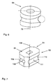
- Figure 6 shows the roller 64 of Figures 4 and 5 in a single representation.
- rollers 64, 65 are also horizontal Movable relative to each other. By appropriate Relative movement of the rollers 64, 65 in the radial direction of the workpiece 2, 2 'can do that when changing the workpiece Machined workpiece 2, 2 'released or the one to be machined Workpieces 2, 2 'are enclosed.
- FIG. 7 finally shows a support body part 94, which together with a corresponding support body part, not shown forms a support body 93 of a support device 91.
- the support body part 94 is about a support body part rotation axis 109 rotating adjustable and in the same way as that Rollers 64, 65 according to Figures 4 and 5 in the respectively set Lockable rotational position.
- the one Support body part 94 assigned second support body part is corresponding designed so that by adjusting the two support body parts an adjustment about the respective support body part axis of rotation of the support device 91 at two different workpiece radiuses or diameter can be made.
- the support device corresponds in construction and mode of operation 91 otherwise the support devices described in detail above 1, 31, 61.
Landscapes
- Engineering & Computer Science (AREA)
- Physics & Mathematics (AREA)
- Optics & Photonics (AREA)
- Mechanical Engineering (AREA)
- Plasma & Fusion (AREA)
- Jigs For Machine Tools (AREA)
- Feeding Of Workpieces (AREA)
- Turning (AREA)
- Laser Beam Processing (AREA)
- Machine Tool Units (AREA)
Applications Claiming Priority (2)
| Application Number | Priority Date | Filing Date | Title |
|---|---|---|---|
| DE29820779U DE29820779U1 (de) | 1998-11-20 | 1998-11-20 | Abstützeinrichtung für ein stangenartiges Werkstück an einer Bearbeitungsmaschine |
| DE29820779U | 1998-11-20 |
Publications (3)
| Publication Number | Publication Date |
|---|---|
| EP1002622A2 true EP1002622A2 (fr) | 2000-05-24 |
| EP1002622A3 EP1002622A3 (fr) | 2003-01-02 |
| EP1002622B1 EP1002622B1 (fr) | 2004-06-23 |
Family
ID=8065610
Family Applications (1)
| Application Number | Title | Priority Date | Filing Date |
|---|---|---|---|
| EP99122603A Expired - Lifetime EP1002622B1 (fr) | 1998-11-20 | 1999-11-13 | Dispositif pour le support d'une pièce en forme de barre sur une machine d'usinage |
Country Status (3)
| Country | Link |
|---|---|
| EP (1) | EP1002622B1 (fr) |
| AT (1) | ATE269777T1 (fr) |
| DE (2) | DE29820779U1 (fr) |
Cited By (2)
| Publication number | Priority date | Publication date | Assignee | Title |
|---|---|---|---|---|
| EP2492041A1 (fr) * | 2011-02-25 | 2012-08-29 | TRUMPF Werkzeugmaschinen GmbH + Co. KG | Dispositif de déchargement flexible pour un dispositif de traitement de tuyau ; Dispositif de soutien pour recevoir et supporter un tuyau ; Méthode de déchargement d'un tuyau utilisant un tel dispositif de déchargement |
| EP3747591A1 (fr) | 2019-06-06 | 2020-12-09 | Bystronic Laser AG | Dispositif de support, machine-outil et procédé pour supporter une pièce en forme de tige |
Families Citing this family (2)
| Publication number | Priority date | Publication date | Assignee | Title |
|---|---|---|---|---|
| ATE458571T1 (de) | 2007-07-17 | 2010-03-15 | Trumpf Werkzeugmaschinen Gmbh | Maschinelle anordnung zum bearbeiten von stabartigen werkstücken mit einer einrichtung zur werkstückabstützung |
| DE102012209079B3 (de) * | 2012-05-30 | 2013-09-26 | Trumpf Werkzeugmaschinen Gmbh + Co. Kg | Verfahren zur Bearbeitung von stabartigen Werkstücken, Bearbeitungsmaschine und Abstützeinrichtung |
Family Cites Families (5)
| Publication number | Priority date | Publication date | Assignee | Title |
|---|---|---|---|---|
| FR923640A (fr) * | 1946-02-08 | 1947-07-11 | Machine à tailler par génération | |
| US4018115A (en) * | 1976-03-29 | 1977-04-19 | Camco, Incorporated | Self-centering steady rest for a machine tool |
| JPS5953125A (ja) * | 1982-09-20 | 1984-03-27 | Nippon Kokan Kk <Nkk> | 放電加工装置 |
| DE4019285A1 (de) | 1990-06-16 | 1991-12-19 | Kieserling & Albrecht | Spanneinrichtung zum gezielten spannen von werkstuecken |
| DE4137071C2 (de) | 1991-11-12 | 1994-04-14 | Kieserling & Albrecht | Führung zum spitzenlosen, radialen Führen von axial bewegten Stangen |
-
1998
- 1998-11-20 DE DE29820779U patent/DE29820779U1/de not_active Expired - Lifetime
-
1999
- 1999-11-13 EP EP99122603A patent/EP1002622B1/fr not_active Expired - Lifetime
- 1999-11-13 DE DE59909801T patent/DE59909801D1/de not_active Expired - Lifetime
- 1999-11-13 AT AT99122603T patent/ATE269777T1/de not_active IP Right Cessation
Cited By (9)
| Publication number | Priority date | Publication date | Assignee | Title |
|---|---|---|---|---|
| EP2492041A1 (fr) * | 2011-02-25 | 2012-08-29 | TRUMPF Werkzeugmaschinen GmbH + Co. KG | Dispositif de déchargement flexible pour un dispositif de traitement de tuyau ; Dispositif de soutien pour recevoir et supporter un tuyau ; Méthode de déchargement d'un tuyau utilisant un tel dispositif de déchargement |
| CN102756216A (zh) * | 2011-02-25 | 2012-10-31 | 通快机床两合公司 | 管加工装置的柔性卸载装置 |
| US9028198B2 (en) | 2011-02-25 | 2015-05-12 | Trumpf Werkzeugmaschinen Gmbh + Co. Kg | Workpiece handling systems and related devices and methods |
| CN102756216B (zh) * | 2011-02-25 | 2015-08-05 | 通快机床两合公司 | 管加工装置的柔性卸载装置 |
| US10023404B2 (en) | 2011-02-25 | 2018-07-17 | Trumpf Werkzeugmaschinen Gmbh + Co. Kg | Workpiece handling systems and related devices and methods |
| EP3747591A1 (fr) | 2019-06-06 | 2020-12-09 | Bystronic Laser AG | Dispositif de support, machine-outil et procédé pour supporter une pièce en forme de tige |
| WO2020244799A1 (fr) * | 2019-06-06 | 2020-12-10 | Bystronic Laser Ag | Dispositif de support, machine-outil et procédé de soutien de pièce à travailler en forme de tige |
| US11072047B1 (en) | 2019-06-06 | 2021-07-27 | Bystronic Laser Ag | Support device, machine tool and method for supporting a rod-shaped workpiece |
| JP2021528265A (ja) * | 2019-06-06 | 2021-10-21 | バイストロニック レーザー アクチェンゲゼルシャフト | 棒状の被加工物を支持するための支持装置、工作機械、および方法 |
Also Published As
| Publication number | Publication date |
|---|---|
| DE59909801D1 (de) | 2004-07-29 |
| DE29820779U1 (de) | 1999-02-25 |
| EP1002622A3 (fr) | 2003-01-02 |
| ATE269777T1 (de) | 2004-07-15 |
| EP1002622B1 (fr) | 2004-06-23 |
Similar Documents
| Publication | Publication Date | Title |
|---|---|---|
| EP0218991B1 (fr) | Dispositif de centrage et de serrage pour objets cylindriques allongés de diamètres différents | |
| EP1260294A1 (fr) | Méthode de tournage | |
| EP3412393B1 (fr) | Dispositifs et procédé de chanfreinage d'une pièce à denture intérieure | |
| EP3412395A2 (fr) | Dispositifs et procédé de chanfreinage d'une pièce à denture intérieure | |
| EP1004393A2 (fr) | Machine-outil avec dispositif pour le changement d'outils automatique | |
| DE2904378A1 (de) | Greifvorrichtung des zangentyps mit zwei schwenkbaren greifarmen zum auffangen und abtransport von fertigen werkstuecken von drehbaenken oder anderen werkzeugmaschinen | |
| DE2648388C2 (de) | Vorrichtung zum Walzen von Lagerringen | |
| DE2217505B2 (de) | Dorniagerung einer Vorrichtung zum Konifizieren von Rohren | |
| EP1002622B1 (fr) | Dispositif pour le support d'une pièce en forme de barre sur une machine d'usinage | |
| EP3670069B1 (fr) | Support de pièce permettant de supporter un matériau tubulaire dans une machine d'usinage de tubes et machine d'usinage de tubes | |
| DE2714706C2 (de) | Zahnradfeinbearbeitungsmaschine | |
| DE2252309C2 (de) | Walzmaschine zum Verformen von zylindrischen metallischen Ringrohlingen | |
| EP1251980A1 (fr) | Procede et dispositif de traitement de parois de soufflure de coquilles de coulage continu | |
| DE3043937C2 (fr) | ||
| DE3734734A1 (de) | Nachlaufsetzstock fuer schleifmaschinen | |
| DE3632436C2 (de) | Radial-Axial-Ringwalzmaschine | |
| DE3333243A1 (de) | Mehrspindel-drehautomat | |
| DE4335580A1 (de) | Vorrichtung zum Trennen einer mehrfach hohen Dosenzarge | |
| EP0119236B1 (fr) | Tour automatique a broches multiples | |
| DE3116389C2 (de) | Mit Eigenantrieb versehene Brennschneidmaschine für Schrägschnitt | |
| DE10024105C2 (de) | Ringwalzvorrichtung | |
| DE2311476A1 (de) | Innenglattwalzwerkzeug | |
| DE172215C (fr) | ||
| DE19814557C1 (de) | Werkstoffstangen-Führungseinrichtung für Drehmaschinen | |
| DE470879C (de) | Gridley-Automat |
Legal Events
| Date | Code | Title | Description |
|---|---|---|---|
| PUAI | Public reference made under article 153(3) epc to a published international application that has entered the european phase |
Free format text: ORIGINAL CODE: 0009012 |
|
| AK | Designated contracting states |
Kind code of ref document: A2 Designated state(s): AT BE CH CY DE DK ES FI FR GB GR IE IT LI LU MC NL PT SE |
|
| AX | Request for extension of the european patent |
Free format text: AL;LT;LV;MK;RO;SI |
|
| PUAL | Search report despatched |
Free format text: ORIGINAL CODE: 0009013 |
|
| AK | Designated contracting states |
Kind code of ref document: A3 Designated state(s): AT BE CH CY DE DK ES FI FR GB GR IE IT LI LU MC NL PT SE |
|
| AX | Request for extension of the european patent |
Free format text: AL;LT;LV;MK;RO;SI |
|
| RIC1 | Information provided on ipc code assigned before grant |
Free format text: 7B 23Q 1/76 A, 7B 23K 26/08 B |
|
| 17P | Request for examination filed |
Effective date: 20021218 |
|
| AKX | Designation fees paid |
Designated state(s): AT CH DE FR GB IT LI |
|
| GRAP | Despatch of communication of intention to grant a patent |
Free format text: ORIGINAL CODE: EPIDOSNIGR1 |
|
| GRAS | Grant fee paid |
Free format text: ORIGINAL CODE: EPIDOSNIGR3 |
|
| RAP1 | Party data changed (applicant data changed or rights of an application transferred) |
Owner name: TRUMPF WERKZEUGMASCHINEN GMBH + CO. KG |
|
| GRAA | (expected) grant |
Free format text: ORIGINAL CODE: 0009210 |
|
| AK | Designated contracting states |
Kind code of ref document: B1 Designated state(s): AT CH DE FR GB IT LI |
|
| REG | Reference to a national code |
Ref country code: GB Ref legal event code: FG4D Free format text: NOT ENGLISH |
|
| REG | Reference to a national code |
Ref country code: CH Ref legal event code: EP |
|
| REG | Reference to a national code |
Ref country code: IE Ref legal event code: FG4D Free format text: GERMAN |
|
| REF | Corresponds to: |
Ref document number: 59909801 Country of ref document: DE Date of ref document: 20040729 Kind code of ref document: P |
|
| GBT | Gb: translation of ep patent filed (gb section 77(6)(a)/1977) |
Effective date: 20040823 |
|
| PG25 | Lapsed in a contracting state [announced via postgrant information from national office to epo] |
Ref country code: AT Free format text: LAPSE BECAUSE OF NON-PAYMENT OF DUE FEES Effective date: 20041113 |
|
| REG | Reference to a national code |
Ref country code: IE Ref legal event code: FD4D |
|
| ET | Fr: translation filed | ||
| PLBE | No opposition filed within time limit |
Free format text: ORIGINAL CODE: 0009261 |
|
| STAA | Information on the status of an ep patent application or granted ep patent |
Free format text: STATUS: NO OPPOSITION FILED WITHIN TIME LIMIT |
|
| 26N | No opposition filed |
Effective date: 20050324 |
|
| PGFP | Annual fee paid to national office [announced via postgrant information from national office to epo] |
Ref country code: CH Payment date: 20081124 Year of fee payment: 10 |
|
| PGFP | Annual fee paid to national office [announced via postgrant information from national office to epo] |
Ref country code: FR Payment date: 20081118 Year of fee payment: 10 |
|
| PGFP | Annual fee paid to national office [announced via postgrant information from national office to epo] |
Ref country code: GB Payment date: 20081121 Year of fee payment: 10 |
|
| REG | Reference to a national code |
Ref country code: CH Ref legal event code: PL |
|
| GBPC | Gb: european patent ceased through non-payment of renewal fee |
Effective date: 20091113 |
|
| REG | Reference to a national code |
Ref country code: FR Ref legal event code: ST Effective date: 20100730 |
|
| PG25 | Lapsed in a contracting state [announced via postgrant information from national office to epo] |
Ref country code: LI Free format text: LAPSE BECAUSE OF NON-PAYMENT OF DUE FEES Effective date: 20091130 Ref country code: FR Free format text: LAPSE BECAUSE OF NON-PAYMENT OF DUE FEES Effective date: 20091130 Ref country code: CH Free format text: LAPSE BECAUSE OF NON-PAYMENT OF DUE FEES Effective date: 20091130 |
|
| PG25 | Lapsed in a contracting state [announced via postgrant information from national office to epo] |
Ref country code: GB Free format text: LAPSE BECAUSE OF NON-PAYMENT OF DUE FEES Effective date: 20091113 |
|
| PGFP | Annual fee paid to national office [announced via postgrant information from national office to epo] |
Ref country code: DE Payment date: 20181120 Year of fee payment: 20 |
|
| PGFP | Annual fee paid to national office [announced via postgrant information from national office to epo] |
Ref country code: IT Payment date: 20181126 Year of fee payment: 20 |
|
| REG | Reference to a national code |
Ref country code: DE Ref legal event code: R071 Ref document number: 59909801 Country of ref document: DE |