EP1002635B1 - Steuern der Extrusion eines Vorformlings abhängig von dem verwendeten Blasformwerkzeug - Google Patents
Steuern der Extrusion eines Vorformlings abhängig von dem verwendeten Blasformwerkzeug Download PDFInfo
- Publication number
- EP1002635B1 EP1002635B1 EP99309118A EP99309118A EP1002635B1 EP 1002635 B1 EP1002635 B1 EP 1002635B1 EP 99309118 A EP99309118 A EP 99309118A EP 99309118 A EP99309118 A EP 99309118A EP 1002635 B1 EP1002635 B1 EP 1002635B1
- Authority
- EP
- European Patent Office
- Prior art keywords
- parison
- molds
- wheel
- mold
- blow molding
- Prior art date
- Legal status (The legal status is an assumption and is not a legal conclusion. Google has not performed a legal analysis and makes no representation as to the accuracy of the status listed.)
- Expired - Lifetime
Links
- 238000001125 extrusion Methods 0.000 title claims abstract description 23
- 238000000071 blow moulding Methods 0.000 claims abstract description 35
- 238000000034 method Methods 0.000 claims description 13
- 238000000465 moulding Methods 0.000 claims description 4
- 238000001514 detection method Methods 0.000 claims 4
- 230000008878 coupling Effects 0.000 claims 1
- 238000010168 coupling process Methods 0.000 claims 1
- 238000005859 coupling reaction Methods 0.000 claims 1
- 238000004519 manufacturing process Methods 0.000 description 14
- 230000007246 mechanism Effects 0.000 description 12
- 238000013459 approach Methods 0.000 description 7
- 238000007664 blowing Methods 0.000 description 7
- 238000013461 design Methods 0.000 description 2
- 230000001360 synchronised effect Effects 0.000 description 2
- 238000012360 testing method Methods 0.000 description 2
- 230000001419 dependent effect Effects 0.000 description 1
- 230000000694 effects Effects 0.000 description 1
- 238000010101 extrusion blow moulding Methods 0.000 description 1
- 230000001939 inductive effect Effects 0.000 description 1
- 238000012423 maintenance Methods 0.000 description 1
- 238000012986 modification Methods 0.000 description 1
- 230000004048 modification Effects 0.000 description 1
- 230000000135 prohibitive effect Effects 0.000 description 1
- 230000011664 signaling Effects 0.000 description 1
Images
Classifications
-
- B—PERFORMING OPERATIONS; TRANSPORTING
- B29—WORKING OF PLASTICS; WORKING OF SUBSTANCES IN A PLASTIC STATE IN GENERAL
- B29C—SHAPING OR JOINING OF PLASTICS; SHAPING OF MATERIAL IN A PLASTIC STATE, NOT OTHERWISE PROVIDED FOR; AFTER-TREATMENT OF THE SHAPED PRODUCTS, e.g. REPAIRING
- B29C49/00—Blow-moulding, i.e. blowing a preform or parison to a desired shape within a mould; Apparatus therefor
- B29C49/42—Component parts, details or accessories; Auxiliary operations
- B29C49/78—Measuring, controlling or regulating
-
- B—PERFORMING OPERATIONS; TRANSPORTING
- B29—WORKING OF PLASTICS; WORKING OF SUBSTANCES IN A PLASTIC STATE IN GENERAL
- B29C—SHAPING OR JOINING OF PLASTICS; SHAPING OF MATERIAL IN A PLASTIC STATE, NOT OTHERWISE PROVIDED FOR; AFTER-TREATMENT OF THE SHAPED PRODUCTS, e.g. REPAIRING
- B29C49/00—Blow-moulding, i.e. blowing a preform or parison to a desired shape within a mould; Apparatus therefor
- B29C49/02—Combined blow-moulding and manufacture of the preform or the parison
- B29C49/04—Extrusion blow-moulding
-
- B—PERFORMING OPERATIONS; TRANSPORTING
- B29—WORKING OF PLASTICS; WORKING OF SUBSTANCES IN A PLASTIC STATE IN GENERAL
- B29C—SHAPING OR JOINING OF PLASTICS; SHAPING OF MATERIAL IN A PLASTIC STATE, NOT OTHERWISE PROVIDED FOR; AFTER-TREATMENT OF THE SHAPED PRODUCTS, e.g. REPAIRING
- B29C49/00—Blow-moulding, i.e. blowing a preform or parison to a desired shape within a mould; Apparatus therefor
- B29C49/28—Blow-moulding apparatus
- B29C49/30—Blow-moulding apparatus having movable moulds or mould parts
- B29C49/36—Blow-moulding apparatus having movable moulds or mould parts rotatable about one axis
-
- B—PERFORMING OPERATIONS; TRANSPORTING
- B29—WORKING OF PLASTICS; WORKING OF SUBSTANCES IN A PLASTIC STATE IN GENERAL
- B29C—SHAPING OR JOINING OF PLASTICS; SHAPING OF MATERIAL IN A PLASTIC STATE, NOT OTHERWISE PROVIDED FOR; AFTER-TREATMENT OF THE SHAPED PRODUCTS, e.g. REPAIRING
- B29C49/00—Blow-moulding, i.e. blowing a preform or parison to a desired shape within a mould; Apparatus therefor
- B29C49/42—Component parts, details or accessories; Auxiliary operations
- B29C49/78—Measuring, controlling or regulating
- B29C2049/787—Thickness
- B29C2049/7871—Thickness of the extruded preform thickness
-
- B—PERFORMING OPERATIONS; TRANSPORTING
- B29—WORKING OF PLASTICS; WORKING OF SUBSTANCES IN A PLASTIC STATE IN GENERAL
- B29C—SHAPING OR JOINING OF PLASTICS; SHAPING OF MATERIAL IN A PLASTIC STATE, NOT OTHERWISE PROVIDED FOR; AFTER-TREATMENT OF THE SHAPED PRODUCTS, e.g. REPAIRING
- B29C49/00—Blow-moulding, i.e. blowing a preform or parison to a desired shape within a mould; Apparatus therefor
- B29C49/42—Component parts, details or accessories; Auxiliary operations
- B29C49/48—Moulds
- B29C49/48185—Moulds with more than one separate mould cavity
- B29C49/4819—Moulds with more than one separate mould cavity having different sizes or shapes of the mould cavities
Definitions
- the present invention relates to plastic blow molding machines.
- blow molding apparatus are typically provided with a plurality of identical molds and are capable of in-line production of identical bottles.
- One type of blow molding apparatus is a wheel type blow molding apparatus comprising a wheel having a plurality of identical molds positioned about the circumference thereof.
- Each mold typically includes two mold halves each comprising a mold cavity half therein so that when the mold halves are closed the mold defines a mold cavity corresponding to the configuration of the article to be molded, such as a bottle.
- the wheel When employed for extrusion blow molding, the wheel will rotate each mold, seriatim, to an extrusion die positioned adjacent to the wheel.
- multiple wheel type blow molding apparatus may be employed simultaneously to increase production output.
- Large production runs allow for continuous wheel operation at full capacity and minimal wheel downtime. economies of scale and reduced costs per bottle are achieved.
- EP 0 464 933 discloses a blowing mold apparatus, in accordance with preamble of claim 1, comprising a wheel configured to rotate about a rotational axis, said wheel comprising; a plurality of molds, whereby the molds are disposed around the rotational axis of the wheel.
- US 3,963,404 discloses a blowing mold apparatus for multiple simultaneous blow molding operations comprising two circumferentially spaced parison forming means disposed around the rotational of a wheel.
- U.S. Patent No. 5,556,648 to Budzynski teaches providing each mold of a wheel type blow molding apparatus with a first and second inner cavity wherein the first cavity may be different from the second cavity, allowing for production of two distinct bottle configurations per mold.
- each mold on the wheel of Budzynski is identical to each of the others.
- the same number of bottles of each configuration will always be produced by the Budzynski apparatus and short run orders can not therefore be accommodated without replacing each mold on the wheel or operating the wheel at less than full capacity.
- the resulting production of a wheel employing these molds would be identical to simultaneously running two wheels, each comprising a different set of identical molds.
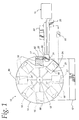
- Figure 1 shows a blow molding machine 10 which rests on a base 12 and includes a rotatable wheel 14 and an extruder 15.
- the wheel 14 comprises a plurality of identical in-line molds 16, each mold 16 having an identical inner cavity 17.
- the wheel further comprises at least one short run in-line mold 19 having a short run inner cavity 21 different in shape and/or size from the plurality of identical inner cavities 17 of each identical in-line mold 16.
- the identical in-line molds 16 and the short run in-line mold 19, are mounted on wheel 14 preferably about the perimeter thereof, for rotation therewith about a rotational axis 13.
- the identical in-line molds 16 and the short run mold 19 each preferably have a pair of mold halves (not shown) that split the respective inner cavities 17, 21 and which open and close at various stations (described below) during rotation about the rotational axis 13 consistent with operation of a conventional wheel type blow molding apparatus.
- the extruder 15 includes a die 30 located adjacent to the wheel 14 and defining a filling station 82 at which a series of hot plastic parisons are extruded from the die 30.
- the die 30 is positioned such that when the identical in-line molds 16 and the short run in-line mold 19 are rotated, seriatim, to the filling station 82 by the wheel 14, the hot plastic parisons extruded from the die 30 may be accepted into the respective inner cavities 17, 21 according to conventional wheel type blow moldings techniques.
- a trigger mechanism 88 synchronized to the rotation of the wheel 14, sends a signal to a controller 20 to timely trigger the extrusion of each successive parison for the respective in-line molds 16, 19.
- a parison supplied by the die 30 will typically have a varying thickness profile along a length thereof to assure that upon the stretching experienced during blowing, the bottle will have the desired wall thickness at the various portions thereof.
- the thickness of the parison for such a bottle may be, for example, relatively thicker at a top and bottom thereof corresponding to a neck and bottom portion of a bottle blown therefrom.
- a pin 28 of the die 30 controls the thickness of a wall of each parison extruded.
- the pin 28 is coupled to a hydraulic cylinder 31 by a drawbar (not shown) such that the hydraulic cylinder 31 may vary the position of the pin 28 during extrusion of a parison.
- the hydraulic cylinder 31 thus raises and lowers the pin 28 to vary the thickness of the parison as it is extruded.
- the controller 20 controls the hydraulic cylinder 31 and thus the positioning of the pin 28.
- the controller 20 has programmed therein, in a manner well-known to those skilled in the art, a preset pin control program or routine to control the vertical movement of the pin 28 during extrusion of each parison and manifests control of the pin 28 via the hydraulic cylinder 31 as is also known in the art. In this manner, the pin control program determines the thickness profile of the parison.
- the controller 20 also induces extrusion of the parison from the die 30 upon indication from the trigger mechanism 88 that a mold is in place and/or that a parison is required.
- the controller 20 is a "Smart Box 2000TM" manufactured by Hunkar Laboratories, Inc., of Cincinnati, Ohio, and is programmed for simultaneous operation of two different pin control programs or routines. In this way two different types of parisons can be provided by the extruder 15.
- a parison is extruded from the die 30 and the mold halves of one of the identical in-line molds 16 close around the parison such that the parison is received by the inner cavity 17.
- another parison is extruded from the die 30 and the mold halves of one of the short run in-line molds 19 close around the parison such that the parison is received by inner cavity 21.
- the parison extruded for the identical in-line molds 16 will differ from the parison extruded for the short run in-line mold 19 to account for the different shape and/or size of the respective cavities 17, 21.
- the wheel 14 in a conventional manner, continues rotation to a blowing station 84 where air is introduced to the inner cavity 17 through a blow needle (not shown).
- the air from the blow needle expands the parison to conform to the shape and size of the inner cavity 17 and form a first container of a first design consistent with conventional blow molding techniques.
- the first container is subsequently cooled while in the inner cavity 17 and is thereafter released by opening the mold halves at a release station 86.
- air is introduced to the inner cavity 21 through the blow needle to form a second container of a second design consistent with conventional blow molding techniques.
- the second container is subsequently cooled while in the inner cavity 21 and thereafter released by opening the mold halves at the release station 86.
- the parison required to produce the first container will usually differ from the parison required to produce the second container.
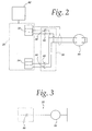
- the preferred controller 20 (the "Smart Box 2000TM” manufactured by Hunkar Laboratories, Inc.) has a first channel A 32 and a second channel B 34.
- the first channel A 32 defines a first pin control program for parisons to be extruded for the identical in-line molds 16.
- the second channel B 34 defines a second pin control program for parisons to be extruded for the short run in-line molds 19.
- a sensor 22 is connected to the controller 20.
- the sensor 22 comprises a position detector 90, such as a photo eye, and a relay 36.
- the relay 36 has normally closed contacts 38 and 40 and normally open contacts, 42 and 44 (described below) wired to a servo valve 56, as depicted in Figures 2 and 3, to facilitate switching back and forth between channel A 32 and channel B 34 on an in-line basis.
- a servo valve 56 as depicted in Figures 2 and 3, to facilitate switching back and forth between channel A 32 and channel B 34 on an in-line basis.
- Properly configured parisons are therefore provided to the identical molds 16 via the profile defined by channel A 32 and to the short run mold 19 via the profile defined by channel B 34.
- the photo eye 90 is positioned adjacent wheel 14 and detects the presence of a metallic or reflective tape 24 on the outer periphery of the wheel 14 by light reflected therefrom.
- the tape 24 is positioned so that the photo eye 90 will signal when the short run mold 19 approaches the die 30.
- channel A 32 or channel B 34 is connected in series with the servo valve 56 at any one time.
- Channel A 32 is the default channel, requiring contact 38 and contact 40 to be in a closed position when any of the identical in-line molds 16 approach the extrusion die 30.
- relay 36 When the photo eye 90 detects the tape 24 on the wheel 14, relay 36 is energized, resulting in contacts 38 and 40 being opened, and contacts 42 and 44 being closed, thus connecting channel B 34 in series with the servo valve 56 and causing the pin 28 to move as defined by the second pin control program such that the parison extruded from the die 30 will conform with the requirements of the approaching short run mold 19.
- the relay 36 remains energized as long as the short run mold 19 is in position to receive the parison. This may be accomplished by selecting an appropriate length of tape 24, by using a second tape positioned to indicate that the relay 36 should be de-energized, by using a timer that energizes the relay 36 for a preset amount of time, or by other methods well known to those skilled in the art.
- a metallic or reflective tape may be placed about the periphery of the wheel 14 at all positions except adjacent to short run mold 19 and the controller 20 or sensor 22 configured to identify the short run mold 19 by the absence of tape.
- Other ways of conveying the proximity of the short run mold 19 to the sensor 22 which become apparent to one of ordinary skill in the art are within the scope of the present invention.
- the trigger mechanism 88 which is synchronized to the rotation of the wheel 14, may be programmed to trigger the relay 36 to switch from channel A 32 to channel B 34 upon the approach of the short run mold 19.
- the trigger mechanism would be configured to trigger the relay 36 after triggering the production of seven parisons.
- the position defector such as the photo eye 90 could thus be eliminated from the sensor 22 of the present invention.
- the trigger mechanism 88 indicates that a parison is required and the controller 20 activates the pin control program defined by channel A 32.
- the photo eye 90 detects the tape 24 on the outer edge of the wheel 14 as the short run mold 19 approaches the die 30 and the photo eye 90 triggers relay 36.
- Relay 36 disconnects the servo valve 56 from channel A 32 of the controller and connects it to channel B 34.
- the appropriate parison is then extruded for mold 19 upon the trigger mechanism 88 inducing extrusion thereof.
- the switch from channel A 32 to channel B 34 occurs after extrusion of the parison to the identical mold 16, but prior to the trigger mechanism 88 triggering the extrusion of a parison for the short run mold 19.
- the blow-molding machine 10 of the present invention rotates the wheel 14 and thereby circulates the plurality of identical in-line molds 16 and the short run in-line mold 19 between the stations 82, 84, 86.
- the trigger mechanism 88 signals the controller 20 to cause the extrusion of a parison from the die 30. If the mold approaching the die 30 is one of the identical in-line molds 16, the controller will remain at the default program defined by channel A 32 and hydraulic cylinder 31 will cause the parameters of the parison to comply with those required to mold a proper first container.
- the sensor 22 will sense the tape 24 and the controller 20 will switch to channel B 34 prior to the trigger mechanism 88 signaling the controller 20 to cause the extrusion of a parison. Therefore, when the trigger mechanism 88 does signal the controller 20 to cause the extrusion of a parison, the hydraulic cylinder 31 causes the pin 28 to extrude the parison according to the parameters required to mold a proper second (short run) container. The controller 20 then switches back to channel A 32 after a parison is received by the short run mold 19.
- the mold halves of that associated mold 16 or 19 will close on the parison consistent with conventional wheel type blow molding techniques.
- the mold 16 or 19 then continues to the blowing station 84 where the blow needle introduces air into the mold cavity 17 or 21 to form a container and the container is cooled in the mold 16 or 19 until it reaches the release station 86 where the mold halves open thus releasing the container from the wheel 14.
- the mold 16 or 19 then continues back toward the die 30 to repeat the cycle.
- the embodiment described above comprises only a single short run mold 19 and the remaining molds on the wheel 14 comprise identical in-line molds 16, it is recognized that the wheel 14 could comprise a plurality of short run molds 19 either adjacent to one another, or interspersed among the identical in-line molds 16. It is contemplated, however, that configuring the wheel 14 such that each of a plurality of short run molds 19 are adjacent to each other will require less switching between channel A 32 and channel B 34 resulting in less wear to the machine 10. Required maintenance for the blow-molding machine 10 of the present invention is thereby minimized.
- each short run mold 19 would have a tape 24 placed near or adjacent thereto on the outer periphery of the wheel 14 to facilitate the switch of the controller 20 to channel B 34 at the approach of each short run mold 19.
- a single piece of tape 24 would be placed adjacent to the first of the plurality of short run molds 19 causing the controller 20 to switch to channel B 34 and the controller 20 would be configured to remain on channel B 34 until a second piece of tape (not shown) is recognized by sensor 22 at which time the controller 20 would switch back to channel A 32 and remain on channel A 32 until the piece of tape 24 returns causing the controller to switch back to channel B 34.
- a timer connected to the relay 36 could also be used to define the number of parisons extruded according to channel B 34.
- the controller 20 could comprise a single channel having two parison routines. Thusly configured, one of the two routines would run each time that a parison is requested. If the controller 20 does not receive an indication from the position detector that the short run mold 19 is adjacent to the die 30, then a first pin profile routine would be delivered to the servo valve 56 to cause the extrusion of a parison required for one of the identical molds 16. If the controller 20 does receive an indication from the position detector that the short run mold 19 is adjacent to the die 30, then a second pin profile routine would be delivered to the servo valve 56 to cause the extrusion of a parison required for the short run mold 19.
- the wheel 14 may comprise only identical molds 16 such that each mold 16 about the wheel is identical to each other mold 16.
- the parison defined by channel B 34 would necessarily, therefore, be provided to a mold 16 identical to the molds 16 into which the parison defined by channel A 32 is provided.
- the variations in the parisons could be employed to effect changes in the final bottle configuration. For example, when channel B 34 causes a thicker parison to be supplied than channel A 32, the resulting bottle will look nearly identical, but will have thicker walls to provide, for example, greater strength.
- Other parameter variations will become apparent to one of ordinary skill in the art and fall within the scope of the present invention.
Landscapes
- Engineering & Computer Science (AREA)
- Manufacturing & Machinery (AREA)
- Mechanical Engineering (AREA)
- Blow-Moulding Or Thermoforming Of Plastics Or The Like (AREA)
- Processing And Handling Of Plastics And Other Materials For Molding In General (AREA)
Claims (19)
- Blasformvorrichtung (10) mit:wobei die Detektionseinrichtung (22) die Nähe wenigstens einer der Formen (16) zur Vorformlingzufuhreinrichtung ermittelt, dadurch gekennzeichnet, dass die Steuereinheit eine erste programmierte Vorformlingparameterroutine, die wenigstens einer der Formen (16) zugeordnet ist, und eine zweite programmierte Vorformlingparameterroutine definiert, die anderen der mehreren Formen (16) zugeordnet ist.einem Rad (14), das mehrere Formen (16) zur Reihenformung umfasst,einer Vorformlingzufuhreinrichtung, die benachbart zu dem Rad (14) angeordnet ist und auf eine Steuereinheit (20) anspricht, undeiner Detektionseinrichtung (22), die benachbart zum Rad (14) angeordnet ist,
- Blasformvorrichtung nach Anspruch 1,
wobei die wenigstens eine der Formen (16) eine Konfiguration besitzt, die sich von der Konfiguration von anderen der mehreren Formen in Größe und/oder Form unterscheidet. - Blasformvorrichtung nach Anspruch 1,
wobei die Steuereinheit (20) dafür ausgelegt ist, in Antwort auf die Detektionseinrichtung (22), welche die Nähe der wenigstens einen der mehreren Formen (16) zur Vorformlingzufuhreinrichtung ermittelt, von der zweiten programmierten Vorformlingparameterroutine zur ersten programmierten Vorformlingparameterroutine zu schalten. - Blasformvorrichtung nach Anspruch 3,
wobei die Detektionseinrichtung (22) eine Photozelle (90) zum Erfassen eines Objekts ist, welches am Rad (14) nahe der wenigstens einen der Formen (16) angeordnet ist. - Blasformvorrichtung nach Anspruch 4,
wobei die Photozelle (90) beim Erfassen des Objekts die Verbindung der ersten programmierten Vorformlingparameterroutine der Steuereinheit mit einem Stellventil (56) freigibt. - Blasformvorrichtung nach Anspruch 1,
wobei die mehreren Formen (16) aus mehreren ersten Formen bestehen und die wenigstens eine der Formen eine einzelne zweite Form mit einer unterschiedlichen Konfiguration als die mehreren ersten Formen umfasst. - Blasformvorrichtung nach Anspruch 1,
wobei die mehreren Formen (16) aus mehreren ersten Formen bestehen und die wenigstens eine der Formen mehrere zweite Formen umfasst, die jeweils eine unterschiedliche Konfiguration als die mehreren ersten Formen besitzen. - Blasformvorrichtung nach Anspruch 1 mit:wobei die mehreren im Wesentlichen identischen Formen und die wenigstens eine unterschiedliche Form um die Drehachse des Rades angeordnet sind.einem Rad (14), das dafür ausgelegt ist, sich um eine Drehachse (13) zu drehen, wobei das Rad umfasst:mehrere im Wesentlichen identische Formen (16), undwenigstens eine Form, die sich von den mehreren im Wesentlichen identischen Formen unterscheidet,
- Blasformvorrichtung nach Anspruch 8,
die ferner einen Positionsdetektor (90) umfasst, der benachbart zum Rad angeordnet ist. - Blasformvorrichtung nach Anspruch 9,
die ferner eine Steuereinheit umfasst, die auf den Positionsdetektor (90) anspricht, wobei die Steuereinheit (20) ein erstes Formprogramm ausführt, wenn die wenigstens eine unterschiedliche Form nicht durch den Positionsdetektor ermittelt wird, und ein zweites Formprogramm, wenn die wenigstens eine unterschiedliche Form durch den Positionsdetektor ermittelt wird. - Blasformvorrichtung nach Anspruch 8,
die ferner eine Vorformlingzufuhreinrichtung umfasst, die benachbart zum Rad (14) angeordnet ist, um eine Reihe von Vorformlingen zuzuführen, die jeweils von einer der mehreren im Wesentlichen identischen Formen (16) und der wenigstens einen unterschiedlichen Form aufzunehmen sind,
wobei die Vorformlingzufuhreinrichtung dafür ausgelegt ist, einen von den mehreren im Wesentlichen identischen Formen aufzunehmenden ersten Vorformling und einen von der wenigstens einen unterschiedlichen Form aufzunehmenden zweiten Vorformling zu extrudieren, wobei sich die wenigstens eine unterschiedliche Form von den mehreren identischen Formen in Größe und/oder Form unterscheidet. - Blasformvorrichtung nach Anspruch 11,
wobei sich der zweite Vorformling von dem ersten Vorformling in der Dicke unterscheidet. - Blasformvorrichtung nach Anspruch 11,
die ferner einen Positionsdetektor (90) umfasst, der benachbart zum Rad (14) angeordnet ist. - Blasformvorrichtung nach Anspruch 13,
wobei die Vorformlingzufuhreinrichtung eine Extrusionsmatrize (30) umfasst und die Einrichtung ferner einen Stift (28) aufweist, der die Wanddicke eines jeden Vorformlings der Reihe von Vorformlingen steuert und wirkmäßig mit der Extrusionsmatrize und einer Steuereinheit (20) verbunden ist, welche auf den Positionsdetektor (90) anspricht und die Manipulation des Stiftes erleichtert, wenn der Positionsdetektor die Nähe der wenigstens einen unterschiedlichen Form ermittelt, so dass die Extrusionsmatrize den zweiten Vorformling extrudiert. - Verfahren zum Blasformen eines Behälters,
das die Schritte umfasst:a) Bereitstellen eines Rades (14), das mehrere Formen (16) zum Reihenformen mehrerer Behälter umfasst,b) Drehen des Rades (14),c) Bereitstellen einer Vorformlingzufuhreinrichtung benachbart zum Rad,d) wirkmäßiges Zuordnen einer ersten programmierten Vorformlingparameterroutine und einer zweiten programmierten Vorformlingparameterroutine zur Vorformlingzufuhreinrichtung,e) Feststellen der Nähe einer speziellen der mehreren Formen (16) zur Vorformlingzufuhreinrichtung, undf) Schalten der wirkmäßigen Zuordnung der einen der ersten programmierten Vorformlingparameterroutine und der zweiten programmierten Vorformlingparameterroutine auf eine wirkmäßige Zuordnung zur anderen der ersten programmierten Vorformlingparameterroutine und der zweiten programmierten Vorformlingparameterroutine. - Verfahren nach Anspruch 15,
wobei der Schritt des Feststellens der Nähe einer speziellen der mehreren Formen (16) den Schritt des Erfassens eines am Rad (14) angeordneten Objekts umfasst. - Verfahren nach Anspruch 16,
das ferner den Schritt des Schaltens eines Relais (36) umfasst, das auf die Erfassung des am Rad angeordneten Objekts anspricht. - Verfahren nach Anspruch 15,
das ferner die Schritte umfasst:g) Zuführen wenigstens eines Vorformlings in Übereinstimmung mit der ersten programmierten Vorformlingparameterroutine,h) Aufnehmen des wenigstens einen Vorformlings in der speziellen der mehreren Formen (16), undi) Zuführen wenigstens eines zusätzlichen Vorformlings in Übereinstimmung mit der zweiten programmierten Vorformlingparameterroutine. - Verfahren nach Anspruch 15,
das ferner die Schritte umfasst:g) Bewirken der Bereitstellung von nur einem einzelnen Vorformling in Übereinstimmung mit der ersten programmierten Vorformlingparameterroutine, wenn festgestellt wird, dass sich die spezielle der mehreren Formen nahe der Vorformlingzufuhreinrichtung befindet, undh) nach der Bereitstellung des einzelnen Vorformlings, Bewirken der Bereitstellung mehrerer Vorformlinge in Übereinstimmung mit der zweiten programmierten Vorformlingparameterroutine, bis die Nähe der speziellen der mehreren Formen (16) zur Vorformlingzufuhreinrichtung erneut festgestellt wird.
Applications Claiming Priority (2)
| Application Number | Priority Date | Filing Date | Title |
|---|---|---|---|
| US193677 | 1988-05-13 | ||
| US09/193,677 US6113841A (en) | 1998-11-17 | 1998-11-17 | Multiple in-line parison control |
Publications (3)
| Publication Number | Publication Date |
|---|---|
| EP1002635A2 EP1002635A2 (de) | 2000-05-24 |
| EP1002635A3 EP1002635A3 (de) | 2001-05-09 |
| EP1002635B1 true EP1002635B1 (de) | 2004-05-26 |
Family
ID=22714562
Family Applications (1)
| Application Number | Title | Priority Date | Filing Date |
|---|---|---|---|
| EP99309118A Expired - Lifetime EP1002635B1 (de) | 1998-11-17 | 1999-11-16 | Steuern der Extrusion eines Vorformlings abhängig von dem verwendeten Blasformwerkzeug |
Country Status (5)
| Country | Link |
|---|---|
| US (2) | US6113841A (de) |
| EP (1) | EP1002635B1 (de) |
| AT (1) | ATE267686T1 (de) |
| CA (1) | CA2290002C (de) |
| DE (1) | DE69917563T2 (de) |
Families Citing this family (17)
| Publication number | Priority date | Publication date | Assignee | Title |
|---|---|---|---|---|
| US6113841A (en) * | 1998-11-17 | 2000-09-05 | Pechiney Plastic Packaging, Inc. | Multiple in-line parison control |
| US6833103B2 (en) * | 2002-02-11 | 2004-12-21 | Salflex Polymers Ltd. | Pressless blow molding |
| US6773251B2 (en) * | 2002-07-11 | 2004-08-10 | Pechiney Emballage Flexible Europe | Segmented wheel disk for extrusion blowmolding apparatus |
| US8449280B2 (en) * | 2010-03-13 | 2013-05-28 | Graham Packaging Company, L.P. | Continuous motion neck calibrated wheel |
| DE102010003350A1 (de) * | 2010-03-26 | 2011-09-29 | Krones Ag | Verfahren zum Herstellen von Kunststoffbehältern |
| US8388333B2 (en) * | 2010-09-30 | 2013-03-05 | Graham Packaging Company, L.P. | Systems for purging polyethylene terephthalate from an extrusion blow molding apparatus |
| US8899960B2 (en) | 2010-10-04 | 2014-12-02 | Graham Packaging Company, L.P. | Air side pivot casting for mold clamping linkage system |
| US8807977B2 (en) | 2010-10-04 | 2014-08-19 | Graham Packaging Company, L.P. | Cam follower slide for mold clamping linkage system |
| US8647103B2 (en) | 2010-10-06 | 2014-02-11 | Graham Engineering Corporation | Modular clamp station with variable pitch |
| US8454342B2 (en) | 2010-10-06 | 2013-06-04 | Graham Engineering Corporation | Modular clamp station |
| US8956707B2 (en) | 2010-11-12 | 2015-02-17 | Niagara Bottling, Llc | Preform extended finish for processing light weight ecologically beneficial bottles |
| USD855901S1 (en) | 2013-05-22 | 2019-08-06 | Judith Lynn Coulter | Pet pillow with attached blanket |
| USD859754S1 (en) * | 2017-04-13 | 2019-09-10 | Judith Lynn Coulter | Pet pad with attached blanket and removable pillow |
| FR3068802B1 (fr) * | 2017-07-10 | 2020-07-17 | Sidel Participations | Procede d'assistance a la programmation d'une unite electronique de commande d'une station de formage |
| US20200031530A1 (en) | 2018-07-30 | 2020-01-30 | Niagara Bottling, Llc | Container preform with threaded tamper evidence finish |
| US11597556B2 (en) | 2018-07-30 | 2023-03-07 | Niagara Bottling, Llc | Container preform with tamper evidence finish portion |
| MX2023010712A (es) * | 2021-03-12 | 2023-10-13 | Niagara Bottling Llc | Preforma de envase. |
Family Cites Families (30)
| Publication number | Priority date | Publication date | Assignee | Title |
|---|---|---|---|---|
| US3355763A (en) * | 1965-05-17 | 1967-12-05 | Egan & Co Frank W | Rotary parison head blow molding machine |
| US3611483A (en) * | 1970-03-19 | 1971-10-12 | Owens Illinois Inc | Container making apparatus control system |
| US3759648A (en) * | 1971-09-15 | 1973-09-18 | Hunker Instr Dev Labor Inc | Extruder control system |
| US3843305A (en) | 1972-02-03 | 1974-10-22 | Monsanto Co | Double parison die head control mechanism |
| US3954370A (en) * | 1973-06-08 | 1976-05-04 | Consupak, Inc. | Method and apparatus for multiple blow molding with rotary turntable |
| US3963404A (en) * | 1973-06-08 | 1976-06-15 | Consupak, Inc. | Method and apparatus for multiple blow molding with rotary turntable |
| US3986807A (en) * | 1973-10-03 | 1976-10-19 | Hitachi Shipbuilding & Engineering Co., Ltd. | Blow molding apparatus |
| DE2544609C3 (de) * | 1975-10-06 | 1984-11-08 | Kautex Werke Reinold Hagen Gmbh, 5300 Bonn | Einrichtung zum Beeinflussen der Länge eines Vorformlings aus thermoplastischem Kunststoff |
| GB2035190B (en) | 1978-11-28 | 1982-10-27 | Toyo Seikan Kaisha Ltd | Rotary blow moulding machine |
| US4786245A (en) * | 1979-12-14 | 1988-11-22 | The Continental Group, Inc. | Blow molding machine |
| JPS5811129A (ja) * | 1981-07-14 | 1983-01-21 | Bridgestone Corp | 制御機構を備えた押出機 |
| US4698012A (en) | 1985-09-20 | 1987-10-06 | Shelby Richard K | Multi-station rotary blow molding machine |
| US4861542A (en) * | 1987-03-23 | 1989-08-29 | Graham Engineering Corporation | Rotary blow molding method |
| US4919607A (en) * | 1988-10-03 | 1990-04-24 | R & B Machine Tool Company | Rotary blow molding machine having mold station blowing/neck finishing mechanisms |
| US4902217A (en) * | 1988-10-03 | 1990-02-20 | R & B Machine Tool Company | Rotary blow molding machine with rotary take-out mechanism having expandible take-out pin |
| NL9001504A (nl) * | 1990-07-02 | 1992-02-03 | Stork Amsterdam | Werkwijze en inrichting voor het vervaardigen van kunststofhouders, zoals flessen, met een uit meerdere lagen bestaande wand. |
| US5229143A (en) * | 1990-08-16 | 1993-07-20 | Kao Corporation | Molding machine |
| JP2795292B2 (ja) * | 1991-03-28 | 1998-09-10 | 宇部興産株式会社 | ブロー成形機のパリソン肉厚制御方法および装置 |
| US5244610A (en) * | 1992-02-14 | 1993-09-14 | Plastipak Packaging, Inc. | Rotary plastic blow molding |
| DE9206649U1 (de) * | 1992-05-15 | 1993-09-16 | Mauser-Werke GmbH, 50321 Brühl | Blasformmaschine |
| JP3377249B2 (ja) * | 1993-04-26 | 2003-02-17 | 昭和電工株式会社 | パリソンの肉厚制御方法およびその装置 |
| US5433916A (en) * | 1993-06-18 | 1995-07-18 | Dowbrands, Inc. | Utilizing multi cavity mold in extrusion blow molding process |
| US5567368A (en) * | 1993-08-31 | 1996-10-22 | Tokai Kogyo Kabushiki Kaisha | Extrusion molding method and extrusion molding apparatus |
| JPH07171882A (ja) * | 1993-10-28 | 1995-07-11 | Tigers Polymer Corp | 可とう性ホースの製造方法および可とう性ホース |
| US5551862A (en) | 1994-06-06 | 1996-09-03 | Wilmington Machinery | Dual parison stacked clamp blow molding apparatus |
| US5645870A (en) | 1995-08-02 | 1997-07-08 | Owens-Brockway Plastic Products Inc. | Blow molding apparatus having a cylindrical hub |
| NO954255L (no) | 1995-10-25 | 1997-04-28 | Norsk Hydro As | Utstyr for stöping av produkter av termoplastisk materiale samt anvendelse av samme |
| US5698241A (en) | 1996-08-19 | 1997-12-16 | Plastipak Packaging, Inc. | Rotary plastic blow molding machine |
| US5840349A (en) | 1997-02-12 | 1998-11-24 | Graham Engineering Corporation | Rotary blow molding machine |
| US6113841A (en) * | 1998-11-17 | 2000-09-05 | Pechiney Plastic Packaging, Inc. | Multiple in-line parison control |
-
1998
- 1998-11-17 US US09/193,677 patent/US6113841A/en not_active Expired - Fee Related
-
1999
- 1999-11-16 AT AT99309118T patent/ATE267686T1/de not_active IP Right Cessation
- 1999-11-16 DE DE69917563T patent/DE69917563T2/de not_active Expired - Lifetime
- 1999-11-16 EP EP99309118A patent/EP1002635B1/de not_active Expired - Lifetime
- 1999-11-17 CA CA002290002A patent/CA2290002C/en not_active Expired - Fee Related
-
2000
- 2000-07-31 US US09/629,473 patent/US6345973B1/en not_active Expired - Fee Related
Also Published As
| Publication number | Publication date |
|---|---|
| EP1002635A2 (de) | 2000-05-24 |
| CA2290002C (en) | 2008-07-22 |
| DE69917563T2 (de) | 2005-06-02 |
| US6345973B1 (en) | 2002-02-12 |
| ATE267686T1 (de) | 2004-06-15 |
| DE69917563D1 (de) | 2004-07-01 |
| CA2290002A1 (en) | 2000-05-17 |
| EP1002635A3 (de) | 2001-05-09 |
| US6113841A (en) | 2000-09-05 |
Similar Documents
| Publication | Publication Date | Title |
|---|---|---|
| EP1002635B1 (de) | Steuern der Extrusion eines Vorformlings abhängig von dem verwendeten Blasformwerkzeug | |
| CA1105216A (en) | Injection blow molding apparatus | |
| EP0336988B1 (de) | Verfahren und Vorrichtung zum Formen einer Flasche mit einem Henkel | |
| US5433916A (en) | Utilizing multi cavity mold in extrusion blow molding process | |
| CN101547783B (zh) | 按坯件扩展点反馈调节方式从坯件制造容器的方法 | |
| CA2451198C (en) | Method and apparatus for making a plastic container and closure combination | |
| EP0162458B1 (de) | Einrichtung zur Temperatursteuerung für eine Spritzstreckblasformmaschine | |
| US5840350A (en) | Modified plastic bottle injection blow-molding apparatus and method | |
| CN101547784A (zh) | 通过根据预吹开始点反馈调节方式制造容器的方法 | |
| CA2331576A1 (en) | Injection moulding tool | |
| US5399302A (en) | Parison length control method for blow molding machine | |
| US3943214A (en) | Method improvements for controlling parison length | |
| RU2305033C2 (ru) | Способ и устройство для изготовления полых изделий | |
| EP0061511B1 (de) | Behälter mit Handgriff und Verfahren und Vorrichtung zu seiner Herstellung | |
| JPH0375493B2 (de) | ||
| US12318989B2 (en) | Method for manufacturing resin wide-mouthed container, manufacturing device, and resin wide-mouthed container | |
| US3044112A (en) | Extrusion blowing apparatus | |
| US3970418A (en) | Apparatus improvements for controlling parison length | |
| US5552105A (en) | Injection blow molding machine with stacked molds | |
| US8366437B2 (en) | Angle link pivot bracket for wheel | |
| WO1992003276A1 (en) | Blow molding of polyethylene terephthalate | |
| EP3254825B1 (de) | Maschine zum formen und blasformen von behältern aus kunststoff vorformlingen. | |
| JP3231491B2 (ja) | 射出延伸ブロー成形装置 | |
| RU2083370C1 (ru) | Установка для изготовления полых изделий из пластмассы | |
| CA1151566A (en) | Handled containers, process and apparatus therefor |
Legal Events
| Date | Code | Title | Description |
|---|---|---|---|
| PUAI | Public reference made under article 153(3) epc to a published international application that has entered the european phase |
Free format text: ORIGINAL CODE: 0009012 |
|
| AK | Designated contracting states |
Kind code of ref document: A2 Designated state(s): AT BE CH CY DE DK ES FI FR GB GR IE IT LI LU MC NL PT SE |
|
| AX | Request for extension of the european patent |
Free format text: AL;LT;LV;MK;RO;SI |
|
| 17P | Request for examination filed |
Effective date: 20001117 |
|
| PUAL | Search report despatched |
Free format text: ORIGINAL CODE: 0009013 |
|
| AK | Designated contracting states |
Kind code of ref document: A3 Designated state(s): AT BE CH CY DE DK ES FI FR GB GR IE IT LI LU MC NL PT SE |
|
| AX | Request for extension of the european patent |
Free format text: AL;LT;LV;MK;RO;SI |
|
| AKX | Designation fees paid |
Free format text: AT BE CH CY DE DK ES FI FR GB GR IE IT LI LU MC NL PT SE |
|
| AXX | Extension fees paid |
Free format text: AL PAYMENT 20011018;LT PAYMENT 20011018;LV PAYMENT 20011018;MK PAYMENT 20011018;RO PAYMENT 20011018;SI PAYMENT 20011018 |
|
| 17Q | First examination report despatched |
Effective date: 20020619 |
|
| GRAH | Despatch of communication of intention to grant a patent |
Free format text: ORIGINAL CODE: EPIDOS IGRA |
|
| GRAS | Grant fee paid |
Free format text: ORIGINAL CODE: EPIDOSNIGR3 |
|
| GRAA | (expected) grant |
Free format text: ORIGINAL CODE: 0009210 |
|
| AK | Designated contracting states |
Kind code of ref document: B1 Designated state(s): AT BE CH CY DE DK ES FI FR GB GR IE IT LI LU MC NL PT SE |
|
| AX | Request for extension of the european patent |
Extension state: AL LT LV MK RO SI |
|
| PG25 | Lapsed in a contracting state [announced via postgrant information from national office to epo] |
Ref country code: NL Free format text: LAPSE BECAUSE OF FAILURE TO SUBMIT A TRANSLATION OF THE DESCRIPTION OR TO PAY THE FEE WITHIN THE PRESCRIBED TIME-LIMIT Effective date: 20040526 Ref country code: LI Free format text: LAPSE BECAUSE OF FAILURE TO SUBMIT A TRANSLATION OF THE DESCRIPTION OR TO PAY THE FEE WITHIN THE PRESCRIBED TIME-LIMIT Effective date: 20040526 Ref country code: IT Free format text: LAPSE BECAUSE OF FAILURE TO SUBMIT A TRANSLATION OF THE DESCRIPTION OR TO PAY THE FEE WITHIN THE PRESCRIBED TIME-LIMIT;WARNING: LAPSES OF ITALIAN PATENTS WITH EFFECTIVE DATE BEFORE 2007 MAY HAVE OCCURRED AT ANY TIME BEFORE 2007. THE CORRECT EFFECTIVE DATE MAY BE DIFFERENT FROM THE ONE RECORDED. Effective date: 20040526 Ref country code: FI Free format text: LAPSE BECAUSE OF FAILURE TO SUBMIT A TRANSLATION OF THE DESCRIPTION OR TO PAY THE FEE WITHIN THE PRESCRIBED TIME-LIMIT Effective date: 20040526 Ref country code: CY Free format text: LAPSE BECAUSE OF FAILURE TO SUBMIT A TRANSLATION OF THE DESCRIPTION OR TO PAY THE FEE WITHIN THE PRESCRIBED TIME-LIMIT Effective date: 20040526 Ref country code: CH Free format text: LAPSE BECAUSE OF FAILURE TO SUBMIT A TRANSLATION OF THE DESCRIPTION OR TO PAY THE FEE WITHIN THE PRESCRIBED TIME-LIMIT Effective date: 20040526 Ref country code: BE Free format text: LAPSE BECAUSE OF FAILURE TO SUBMIT A TRANSLATION OF THE DESCRIPTION OR TO PAY THE FEE WITHIN THE PRESCRIBED TIME-LIMIT Effective date: 20040526 Ref country code: AT Free format text: LAPSE BECAUSE OF FAILURE TO SUBMIT A TRANSLATION OF THE DESCRIPTION OR TO PAY THE FEE WITHIN THE PRESCRIBED TIME-LIMIT Effective date: 20040526 |
|
| REG | Reference to a national code |
Ref country code: GB Ref legal event code: FG4D |
|
| REG | Reference to a national code |
Ref country code: CH Ref legal event code: EP |
|
| REG | Reference to a national code |
Ref country code: IE Ref legal event code: FG4D |
|
| REF | Corresponds to: |
Ref document number: 69917563 Country of ref document: DE Date of ref document: 20040701 Kind code of ref document: P |
|
| PG25 | Lapsed in a contracting state [announced via postgrant information from national office to epo] |
Ref country code: SE Free format text: LAPSE BECAUSE OF FAILURE TO SUBMIT A TRANSLATION OF THE DESCRIPTION OR TO PAY THE FEE WITHIN THE PRESCRIBED TIME-LIMIT Effective date: 20040826 Ref country code: GR Free format text: LAPSE BECAUSE OF FAILURE TO SUBMIT A TRANSLATION OF THE DESCRIPTION OR TO PAY THE FEE WITHIN THE PRESCRIBED TIME-LIMIT Effective date: 20040826 Ref country code: DK Free format text: LAPSE BECAUSE OF FAILURE TO SUBMIT A TRANSLATION OF THE DESCRIPTION OR TO PAY THE FEE WITHIN THE PRESCRIBED TIME-LIMIT Effective date: 20040826 |
|
| PG25 | Lapsed in a contracting state [announced via postgrant information from national office to epo] |
Ref country code: ES Free format text: LAPSE BECAUSE OF FAILURE TO SUBMIT A TRANSLATION OF THE DESCRIPTION OR TO PAY THE FEE WITHIN THE PRESCRIBED TIME-LIMIT Effective date: 20040906 |
|
| PG25 | Lapsed in a contracting state [announced via postgrant information from national office to epo] |
Ref country code: LU Free format text: LAPSE BECAUSE OF NON-PAYMENT OF DUE FEES Effective date: 20041116 Ref country code: IE Free format text: LAPSE BECAUSE OF NON-PAYMENT OF DUE FEES Effective date: 20041116 |
|
| LTIE | Lt: invalidation of european patent or patent extension |
Effective date: 20040526 |
|
| PG25 | Lapsed in a contracting state [announced via postgrant information from national office to epo] |
Ref country code: MC Free format text: LAPSE BECAUSE OF NON-PAYMENT OF DUE FEES Effective date: 20041130 |
|
| REG | Reference to a national code |
Ref country code: CH Ref legal event code: PL |
|
| NLV1 | Nl: lapsed or annulled due to failure to fulfill the requirements of art. 29p and 29m of the patents act | ||
| ET | Fr: translation filed | ||
| PLBE | No opposition filed within time limit |
Free format text: ORIGINAL CODE: 0009261 |
|
| STAA | Information on the status of an ep patent application or granted ep patent |
Free format text: STATUS: NO OPPOSITION FILED WITHIN TIME LIMIT |
|
| 26N | No opposition filed |
Effective date: 20050301 |
|
| REG | Reference to a national code |
Ref country code: IE Ref legal event code: MM4A |
|
| PG25 | Lapsed in a contracting state [announced via postgrant information from national office to epo] |
Ref country code: PT Free format text: LAPSE BECAUSE OF NON-PAYMENT OF DUE FEES Effective date: 20041026 |
|
| PGFP | Annual fee paid to national office [announced via postgrant information from national office to epo] |
Ref country code: DE Payment date: 20121128 Year of fee payment: 14 Ref country code: FR Payment date: 20121206 Year of fee payment: 14 |
|
| PGFP | Annual fee paid to national office [announced via postgrant information from national office to epo] |
Ref country code: GB Payment date: 20121126 Year of fee payment: 14 |
|
| REG | Reference to a national code |
Ref country code: DE Ref legal event code: R119 Ref document number: 69917563 Country of ref document: DE |
|
| GBPC | Gb: european patent ceased through non-payment of renewal fee |
Effective date: 20131116 |
|
| REG | Reference to a national code |
Ref country code: FR Ref legal event code: ST Effective date: 20140731 |
|
| PG25 | Lapsed in a contracting state [announced via postgrant information from national office to epo] |
Ref country code: DE Free format text: LAPSE BECAUSE OF NON-PAYMENT OF DUE FEES Effective date: 20140603 |
|
| REG | Reference to a national code |
Ref country code: DE Ref legal event code: R119 Ref document number: 69917563 Country of ref document: DE Effective date: 20140603 |
|
| PG25 | Lapsed in a contracting state [announced via postgrant information from national office to epo] |
Ref country code: FR Free format text: LAPSE BECAUSE OF NON-PAYMENT OF DUE FEES Effective date: 20131202 Ref country code: GB Free format text: LAPSE BECAUSE OF NON-PAYMENT OF DUE FEES Effective date: 20131116 |