EP1002673B2 - Attelage de remorque - Google Patents
Attelage de remorque Download PDFInfo
- Publication number
- EP1002673B2 EP1002673B2 EP00101823A EP00101823A EP1002673B2 EP 1002673 B2 EP1002673 B2 EP 1002673B2 EP 00101823 A EP00101823 A EP 00101823A EP 00101823 A EP00101823 A EP 00101823A EP 1002673 B2 EP1002673 B2 EP 1002673B2
- Authority
- EP
- European Patent Office
- Prior art keywords
- ball
- coupling
- trailer coupling
- ball neck
- rest position
- Prior art date
- Legal status (The legal status is an assumption and is not a legal conclusion. Google has not performed a legal analysis and makes no representation as to the accuracy of the status listed.)
- Expired - Lifetime
Links
Images


Classifications
-
- B—PERFORMING OPERATIONS; TRANSPORTING
- B60—VEHICLES IN GENERAL
- B60D—VEHICLE CONNECTIONS
- B60D1/00—Traction couplings; Hitches; Draw-gear; Towing devices
- B60D1/24—Traction couplings; Hitches; Draw-gear; Towing devices characterised by arrangements for particular functions
- B60D1/246—Traction couplings; Hitches; Draw-gear; Towing devices characterised by arrangements for particular functions for actuating the hitch by powered means
-
- B—PERFORMING OPERATIONS; TRANSPORTING
- B60—VEHICLES IN GENERAL
- B60D—VEHICLE CONNECTIONS
- B60D1/00—Traction couplings; Hitches; Draw-gear; Towing devices
- B60D1/48—Traction couplings; Hitches; Draw-gear; Towing devices characterised by the mounting
- B60D1/52—Traction couplings; Hitches; Draw-gear; Towing devices characterised by the mounting removably mounted
-
- B—PERFORMING OPERATIONS; TRANSPORTING
- B60—VEHICLES IN GENERAL
- B60D—VEHICLE CONNECTIONS
- B60D1/00—Traction couplings; Hitches; Draw-gear; Towing devices
- B60D1/48—Traction couplings; Hitches; Draw-gear; Towing devices characterised by the mounting
- B60D1/54—Traction couplings; Hitches; Draw-gear; Towing devices characterised by the mounting collapsible or retractable when not in use, e.g. hide-away hitches
Definitions
- the invention relates to a towing hitch for motor vehicles, especially passenger cars, with a coupling ball, with a ball neck, one end portion is bent and carries the coupling ball and the other end portion is connected to a bearing element, with a bearing element pivotally mounted vehicle-fixed pivot bearing whose only pivot axis is oriented obliquely to a longitudinal direction parallel to the vehicle longitudinal vertical plane, wherein the ball neck with the coupling ball by pivoting about the pivot axis of a working position in which the ball neck extends substantially along the vertical longitudinal plane, in a rest position in which the ball neck approximately extends transversely to the longitudinal plane, and vice versa is pivotable.
- Such a trailer coupling is from the DE-C-26 19 913 known.
- the invention is therefore an object of the invention to improve a trailer coupling of the generic type such that it is easy to use.
- the controller detects the working position of the ball neck via a sensor detecting the locking position of the locking device.
- the working position is detected only if at the same time the locking device is in the locking position and thus it is also ensured that the ball neck is not only in the working position, but is also secured by the locking device.
- Such a particularly secure detection of the working position for example, be realized that both the working position of the ball neck as such and the locking position of the locking device are detected either via a mechanical AND link and a sensor or two of these each detecting sensors.
- the controller detects the working position and / or the rest position of the ball neck via a respective sensor associated with these positions, so that via this sensor is a direct, independent of the drive feedback to the controller.
- an emergency shutdown is provided.
- control designed so that it is interrupted during actuation of the switching element in the course of a pivoting movement of the ball neck.
- Another safety function is obtained by the fact that the control torque detection for the drive, which detects an exceeding of a torque threshold of the drive. This ensures that even if the ball neck or the coupling ball run unexpectedly against an obstacle, neither the obstacle nor the clutch according to the invention can cause damage.
- the torque detection could now serve to deliver a signal to the controller, which causes them to interrupt the pivotal movement of the ball neck.
- the torque detection outputs a signal when the torque threshold is exceeded, so that the control reverses the previous pivoting direction. This is in the same way, as already stated when pressing the switching device, on the one hand ensures that ball neck or coupling ball does not run against an obstacle and sustainable continue to act against this, but interrupt their pivotal movement and even reverse and thus, for example, in the position from which they come, swing back.
- the torque threshold is the same in all stages of the pivoting movement.
- the torque threshold be higher in the working position and the rest position until it leaves the same lies as after.
- the breakaway torque for leaving the working position or rest position is increased, but this represents no loss of security, as long as after leaving the working position or rest position, the torque threshold is lowered again.
- Torque detection can work in many different ways. A simple solution to this provides that the torque detection detects the current consumption of the motor.
- a control for operating the motor is preferably provided, this control is suitably designed so that this either a pivoting of the ball neck or driving the vehicle allows, that is, no pivoting of the ball neck while driving the vehicle permits.
- Such a design of the controller has the great advantage that it ensures optimum safety in the event that a pivoting of the ball neck while driving is triggered either due to incorrect operations or other malfunctions.
- the controller blocks the drive for pivoting the ball neck when the engine of the vehicle is running.
- the pivoting of the ball neck can only take place when the engine of the vehicle is turned off. This ensures that during the ride no pivoting of the ball neck can be done by the drive provided with a motor.
- such a blocking of the drive by means of the controller is realized in that the controller interrupts a power supply for the drive.
- a further improvement of the operating safety is achieved in that the controller only allows running of the engine of the vehicle when the ball neck is in the working position or in the rest position, so that in turn it is ensured that an operation of the vehicle only possible if the ball neck is in one of two defined positions, namely the working position or the rest position.
- all operating errors are such that when standing in any intermediate position between the working position and the rest position ball neck driving with the vehicle is excluded.
- a particularly advantageous solution provides that the switching element and the controller are arranged in the trunk of the motor vehicle.
- Such an arrangement offers the advantage of a relatively simple accommodation of the control, in particular close to the other coupling components, and also the advantage that the switching element can also be attached to the controller and the control can be actuated from the trunk.
- a particularly advantageous embodiment of a trailer coupling provides that the coupling only one electrical functional group, comprising the controller, and only one associated with this mechanical functional group, comprising the cross member body with the mounted on this drive, the pivot bearing and the ball neck mounted on this covered with coupling ball.
- the Drive acts on the bearing element via a self-locking gear, since in this case already the self-locking gear can be used to fix the ball neck with the coupling ball in the rest position and / or the working position.
- no forces acting on the coupling ball act as moments on the engine of the drive, so that the engine only has to be designed so that it is able to pivot without force on the coupling ball and ball neck, this between the working position and the rest position ,
- the pivoting movement of the ball neck is limited by a stop fixed to the vehicle.
- this is a stop which acts on the bearing element.
- the bearing element has a projection which acts at least in the rest position or the working position against the vehicle-fixed stop.
- the working position is determined in this case with the acting against a vehicle-fixed stop projection, while the rest position of the ball neck, for example, also be determined that the ball neck itself comes with any area thereof in the rest position on a vehicle-fixed stop surface to rest.
- the ball neck in the working position can be fixed by the locking device.
- a locking device it is possible to fix in the same way as in the previously known manually removable and usable couplings, the ball neck in the working position reliable.
- the locking device is designed so that it automatically transitions into an interlocking position upon reaching the working position of the ball neck and thus fixes the ball neck in the working position. This ensures that - especially when operating the solution according to the invention by means of an electric drive - the ball neck is necessarily locked when reaching the working position in this working position.
- the trigger can be actuated in many different ways. In the simplest case, it would be conceivable to provide a manual trigger.
- a trigger drive could be, for example, a trigger-actuating controllable solenoid.
- a particularly expedient solution in particular with regard to the simplicity and cost-effectiveness of the structure, provides that the trigger of the drive for pivoting the ball neck is actuated, d. h., That, for example, the drive motor with which the ball neck is pivotable, at the same time also used to actuate the trigger.
- a particularly advantageous installable solution provides that the pivot bearing is held at an approximately in the same orientation as the rear bumper transverse to the vehicle longitudinal direction extending cross member body.
- Such a cross member body provides the ability to provide an independent of the bumper unit fixation when equipping the vehicles.
- crossbeam body is arranged between two additional parts forming side supports and connected to these and when the side support extend to vehicle-mounted breakpoints is particularly advantageous.
- three units are provided for fixing the pivot bearing on the vehicle, the cross member body and the side support are preassembled, so that the entire unit of cross member body and side support is to be mounted on vehicle-mounted breakpoints.
- a particularly favorable adaptation to a wide variety of vehicle types is possible when the cross member body via a relative to a transverse to the vehicle longitudinal direction transverse axis in different rotational positions fixable connection to the side supports can be fastened.
- This allows on the one hand to provide a firm connection between the cross member body and the side beams in the manufacture of the same, on the other hand, an additional Degree of freedom in the adaptation of the unit of cross member body and side members to individual vehicle types to have, namely the fact that the cross member body is mounted in different rotational positions relative to the side members.
- connection between the cross member body and the side members has two interlocking and only about the transverse axis against each other rotatable fasteners. This is a positive and especially suitable for large forces connection is created, which has only one degree of freedom, namely the possibility of a rotatable fixing of the cross member body relative to the side beams.
- a particularly preferred compound due to its simplicity and stability provides that this has in the direction of the transverse axis to form a plug-in nested fasteners.
- the connecting elements are designed so that they transmit the forces acting transversely to the transverse axis forces through the positive connection.
- a particularly favorable solution in particular with regard to the required installation space, provides that the ball neck in the rest position extends at least in sections along the cross member body.
- a particularly suitable position provides that the ball neck with the coupling ball in the rest position is such that a connecting line between the bearing element and coupling ball approximately along the cross member body in the vehicle transverse direction.
- the ball neck and the coupling ball lie in the rest position between the ends of the cross member body.
- the stops for limiting the pivotal movement of the ball neck in the working position and the rest position are held on the cross member body, so that these are arranged on the same base as the pivot bearing and optionally the drive.
- an advantageous embodiment provides that the drive for the pivoting movement is arranged on a side opposite the ball neck and coupling ball side of the pivot bearing, so that there is an extremely compact design of the trailer coupling according to the invention, which when installed in a vehicle the smallest possible space needed behind the bumper.
- a particularly advantageous embodiment with respect to the assembly provides that the cross member body is a molded part to which the pivot bearing is formed.
- an advantageous embodiment provides that the cross member body is a molded part and has a receptacle for the drive, so that it is not necessary to provide additional holding elements for the connection of cross member body and drive.
- the cross member is a molded part, which has a receptacle for the self-locking gear, so that the self-locking gear, which may have to absorb large forces, can be mounted on the cross member body with the sufficient stability and as simple as possible.
- cross member body is a molded part to which a stopper is formed, which must also be designed to accommodate large forces and thus particularly favorable already realized by the molding part is particularly advantageous.
- the cross member body is a molded part, which has a receptacle for the locking device.
- the cross member body is as a molded part in different types produced.
- a cross member body a welded, bent or forged steel part.
- a casting as a molded part, which molding may be a cast steel part or a Weinmetallgußteil, in particular an aluminum casting.
- a further advantageous embodiment provides that a projection of a coupling ball central axis on the vertical longitudinal plane when pivoting the ball neck about the pivot axis from the working position to the rest position undergoes rotation through an angle of at least 80 ° and that a lowest point of ball neck and coupling ball in the Rest position is at least at the level of a lowest point of the ball neck in working position.
- the projection of the coupling ball central axis onto the vertical longitudinal plane when pivoting about the pivot axis experiences a rotation of more than 90 °, more preferably more than 100 °, and preferably more than 120 °.
- the coupling ball center axis is pivoted by more than 90 °, preferably more than 120 °, the rest position space required by ball neck and coupling ball in the rest position can be particularly small in the vehicle direction.
- the rotation of the projection of the coupling ball central axis on the longitudinal plane is a maximum of 210 °, more preferably a maximum of 180 °, preferably a maximum of 160 °.
- the projection of the coupling ball central axis on the vertical longitudinal plane with the horizontal encloses an angle in the range of about 30 ° to about 150 °, more preferably in the range of about 40 ° to about 140 °, so that in the vehicle longitudinal direction short-build rest position space is available.
- a particularly advantageous solution of the object according to the invention can be achieved if the projection of the coupling ball central axis extends to the vertical longitudinal plane in the rest position at an angle of at least 170 ° with respect to a horizontal. It is even better if the projection of the coupling ball central axis on a vertical longitudinal plane in the rest position at an angle of more than 180 ° is even better than 210 ° with respect to a horizontal.
- a further advantageous solution of the object according to the invention can be achieved in that the coupling ball is arranged in the rest position at a distance from a road surface, which is equal to or smaller than a distance of the bent end portion of the road surface and that a lowest point of ball neck or coupling ball in the rest position at least at the level of a lowest point of the ball neck in working position.
- This definition also defines a condition which makes it possible to position the unit of ball neck and coupling balls with a favorable space requirement and sufficient height above the road surface.
- the ball neck with the coupling ball can then be positioned when in the rest position, the plane of curvature of the ball neck with a horizontal plane at an angle in the range of about 30 ° to about 150 °, more preferably about 40 to about 140 °.
- a particularly advantageous realization of the solution according to the invention provides that the projection of the pivot axis is inclined to an angle parallel to the vehicle longitudinal direction vertical longitudinal plane at an angle to the horizontal, which is in an angular range of about 0 ° to about 60 °.
- the ball neck and coupling ball can then be positioned in the rest position if the angle range extends to a maximum of 50 °.
- the ground clearance during pivoting can be improved by starting the angular range at least 15 °, more preferably at least 30 °.
- angle range between approximately 30 ° and approximately 65 ° is more preferably between approximately 40 ° and approximately 60 °.
- the projection of the pivot axis is inclined to a vertical, perpendicular to the vehicle longitudinal direction transverse plane at an angle to the horizontal, which is in an angular range of about 0 ° to about 60 °.
- the object of the invention can be achieved in a further embodiment in an advantageous manner that the cranked end portion of the ball neck in the rest position on a side facing away from the road surface at a level of a lowest point of the idle coupling ball extending horizontal plane and that the horizontal plane at least at the level of the lowest point of the standing in the working position ball neck.
- the entire ball neck lies, in particular with the bearing element in the rest position, on a side facing away from the road surface at a horizontal plane lying at the lowest point of the idle coupling ball, so that the entire ball neck is maximally up to this plane. preferably on the side facing away from the road surface of this plane extends.
- the ball neck with the coupling ball can then be positioned when in the rest position, the plane of curvature of the ball neck with a horizontal plane forms an angle in the range of about 30 ° to about 150 °, more preferably about 40 ° to about 140 °.
- a further definition of the solution according to the invention provides that the coupling ball has a the cranked end of the ball neck opposite upper ball cap surface, which faces away in the working position of the road surface and in the rest position, this at least obliquely facing.
- a solution according to the invention is particularly advantageous when the pivot bearing is arranged asymmetrically offset with respect to the plane of curvature in the direction of a side of a plane of curvature of the ball neck opposite the rest position.
- the offset may for example be so small that the pivot bearing is only asymmetric to the plane of curvature of the ball neck, but is still cut from the plane of curvature.
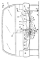
- FIG. 1 to 3 shown, designated as a whole with 10 embodiment of a trailer coupling according to the invention comprises a coupling ball 12 which is supported by a ball neck 14, wherein the ball neck 14 has a bent end portion 16 on which the coupling ball 12 sits directly and this bent end portion 16 opposite a lower end portion 18, which is connected to a bearing element 20, wherein this bearing element 20 in a pivot bearing 22, for example comprising a bearing body 24 with two bearing flanges 26 and 28, about a pivot axis 30 is pivotable.
- the bearing element 20 preferably comprises a pivot bearing 22, for example between the bearing flanges 26 and 28 lying pivoting body 19 and extending from the pivot body 19 to the end portion 18 of the ball neck 14 arm 21, wherein the arm in a working position A of the ball neck 14A obliquely to the plane of curvature K. the ball neck 14 extends, in a direction opposite to a rest position R of the ball neck direction, so that the pivot bearing 22 and the pivot body 19 is located substantially laterally of the curvature plane K.
- the pivot bearing 22 is in turn held on a generally designated 32 cross member body, which extends transversely to a vehicle longitudinal direction 34 of a generally designated 36 motor vehicle and along a rear bumper unit 38 thereof.
- the cross member body 32 is preferably seated between two side beams 40 and 42, which adjoin one another in opposite to the vehicle longitudinal direction 34 vehicle transverse direction 44 opposite ends 46 and 48 of the cross member body 32 and extending to lateral attachment portions 50, 52 on a vehicle body 54.
- the pivot axis 30 extends obliquely to a direction parallel to the vehicle longitudinal direction 34 extending vertical longitudinal plane 60, wherein the projection of the pivot axis 30 in a horizontal plane 62 with the longitudinal plane 60 or the vehicle longitudinal direction 34 forms an angle ⁇ , which for example in an angular range of about 50 ° is about 60 °, preferably about 55 ° ( Fig. 3 ).
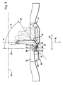
- the projection of the pivot axis 30 closes in the longitudinal plane 60 - as in Fig. 2 illustrated with an extending in the longitudinal plane 60 horizontal 64 an angle ⁇ which is for example in an angular range of about 35 ° to about 45 °, preferably about 40 °.
- the projection of the pivot axis 30 in a parallel to the vehicle transverse direction 44 and perpendicular to the longitudinal plane 60 vertical vertical plane 66 closes - as in Fig. 1 shown with an extending in this horizontal 68 an angle ⁇ which is for example in an angular range of about 25 ° to about 35 °, preferably about 30 °.
- the ball neck 14 is about the pivot axis 30 from a working position A, in which a coupling ball central axis 70 is approximately perpendicular to the horizontal plane 62 and the ball neck 14, as in Fig. 1 and 3 shown in a plane parallel to the longitudinal plane 60 and extending through the coupling ball center axis 70 extending curvature plane K extends to the bearing element 20, pivotable in the rest position R.
- the coupling ball central axis 70R extends obliquely to the horizontal plane 62, extending from the stationary at rest coupling ball 12R of the adjoining this bent end portion 16R of the ball neck 14R from a side facing away from a road surface 72 of the coupling ball 12R starting.
- the coupling ball 12A in the working position A away from the road surface 72 faces upwards and the ball neck 14 extends from the coupling ball 12A in the direction of the road surface 72 down, while in the rest position R, the coupling ball 12R to the road surface 72nd indicates while the ball neck 14 R, starting from the coupling ball 12 R upwards, d. H. away from the road surface 72 in an arc to the pivot bearing 22 extends.
- the coupling ball 12 R substantially above a bottom group of the body or the bumper unit 38, extending in the longitudinal plane 60 and 15 ° relative to the road surface 72 inclined line of sight S to the ball neck 14 R with the Clutch ball 12R substantially invisible to an outsider to position.
- the movement of the ball neck 14 with the coupling ball 12 and in particular the pivoting thereof can be - as in Fig. 2 represented - particularly easy by the representation of the projection the coupling ball central axis 70 on the vertical longitudinal plane 60 or a plane parallel to this described.
- the projection of the coupling ball central axis 70A in the longitudinal plane 60 at an angle WA with the horizontal 64 of about 90 °.
- the coupling ball central axis 70 is pivoted so far during the pivoting of the ball neck 14 with the coupling ball 12 from the working position A in the rest position R, that the projection of the coupling ball central axis 70 in the longitudinal plane 60 undergoes a rotation, to such an extent that the projection of the coupling ball central axis 70R in the rest position in the longitudinal plane 60 with the horizontal 64 includes an angle WR which is greater than 180 °.
- the angle is preferably more than 225 °.
- the ball neck 14 R and the coupling ball 12 R in the rest position R as possible to be invisible to a viewer of the motor vehicle 36 is in the rest position R, the coupling ball 12 R on a side facing away from the road surface 72 a horizontal plane 76, the height above the road surface Is defined by a lower edge of the pivot bearing 22, or touches this horizontal plane 76, so that a lowest point PR from the ball neck 14 R and coupling ball 12 R at rest - in this case, the lowest point PR of the coupling ball 12 R in a horizontal plane 77 - is higher as the horizontal plane 76 ( Fig. 1 ) and higher than a lowest point PA of the ball neck 12A in working position A.
- the ball neck 14R and the coupling ball 12R are in the rest position R in a rest position space 78 which lies between the rear bumper unit 38 and the vehicle body 54 and extends along the bumper unit 38 in the vehicle transverse direction 44.
- the rest position space 78 is located above a bottom-side surface 79 of the power tool 36 defined by a bottom group of the vehicle body 54 and the bumper unit 38 (FIG. Fig. 2 ).
- a designated as a whole with 80 drive which includes an electric motor 82 and, for example, a self-locking or self-locking gear 84.
- a bevel gear 88 On an output shaft 86 of the gear 84 is seated a bevel gear 88, with which a bevel gear 90 is driven, which is rotatably connected to the bearing element 20 and preferably located on one of the road surface 72 facing side of the bearing element 20.
- the self-locking gear 84 is formed so that it is blocked against outer, acting on the output shaft 86 torques and driven only via the motor 82.
- the self-locking gear 84 is formed as a worm gear.
- the drive 80 ' also includes the electric motor 82 and a gear 84' connected thereto, which does not necessarily have to be designed as a self-locking gear, but represents, for example, an angular gear.
- the gear 84 ' drives a worm gear 92 seated on its output shaft which, in turn, drives a gear 94 non-rotatably connected to the bearing member 20 and meshing with the worm wheel 92, which together form a self-locking gear.
- the drive 80 is disposed on a side R of the ball neck 14 R opposite side of the pivot bearing 22 and fixed to the cross member body 32.
- the bearing member 20 for example, provided with a nose-like projection 100 which rests in the working position on a fixedly connected to the cross member body 32 stop 102, wherein the stopper 102 is formed, for example, as a between the bearing flanges 26 and 28 extending bolt.
- the drive via the self-locking gear 84 or the worm wheel 92 with the gear 94 which also acts as a self-locking gear, it would in principle not be necessary to provide an additional backup when the projection 100 on the stop 102, as there the self-locking gear 84 and 92, 94 counteracts a swiveling out in the direction of the arrow 106 from the working position A out and this does not allow.
- a locking device 110 is provided, for example, has a pivotally mounted about an axis 112 locking pawl 114 which in its the ball neck 14A in working position A locking position, shown in FIG Fig. 5 with solid lines, the projection 100 engages behind a stop 102 on the opposite side 116 and fixed with a locking surface 118 against movement in Ausschwenkcardi 106 so that the projection 100 between the locking surface 118 and the stop 102 is secured against pivoting.
- a spring 120 is provided, which acts on the locking pawl 114 in the direction of its locking position and, for example, on the bearing body 24th supported.
- the locking pawl 114 is still provided with an inlet ramp 122 which at an acute angle to the locking surface 118th runs and facing in Einschwenkcardi 104 approaching projection 100, so that moving in Einschwenkcardi 104 and acting against the inlet slope 122 projection 100, the locking pawl 114 moved out of its locking position against the action of the spring 120 and thus has the opportunity over the inlet slope 122 away to move into its working position A, in which it rests against the stop 102. In this working position A of the projection 100, the locking pawl 114 again moves in the direction of its locking position, wherein the locking surface 118 engages behind the side 116 of the projection 100 and fixes it.
- an actuation of the locking pawl 114 is required, which in dashed lines in their Fig. 5 indicated unlocked position moves. In the simplest case, the actuation of the locking pawl 114 takes place manually.
- This actuation of the locking pawl 114 takes place in the presence of a motor drive 80, 80 'preferably via a cam 80 which is movable by the drive 80 or 80', the cam 124 being effected, for example, by a frictionally driven element which, when the drive starts, opposes the cam 124 the bearing element 20 driving ahead, so that the locking pawl 114 already in their in Fig. 5 indicated by dashed lines unlocking position before the projection 100 moves away from the stop 102 in Ausschwenkraum 106.
- Such advance of the drive of the cam 124 for example, by a game between the frictionally driven and the cam 124 moving element and the drive of the bearing element 20, for example via the bevel gear 90 or the gear 94, realized.
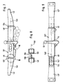
- the cross member body 32 ' as a molded part, for example as a casting formed, to which both the entire pivot bearing 22 with all the details and a receptacle 130 for the drive 80 and a receptacle for the locking device 110 are integrally formed, so that a mounting of the entire drive 80 in a simple manner is possible.
- the cross member body 32 in the region of its two ends 46 and 48 provided with mounting flanges 132 and 134, wherein each of the mounting flanges 132, 134, as in Fig. 8 shown, an opening 136, in which the respective side support 40, 42 with a pin 138 form-fitting, but rotatable about an axis 140, engages.
- the two pins 138 of the two side supports 40, 42 arranged coaxially with each other, so is the total of the cross member body 32 'relative to the side beams 40 and 42 about the axis 140, which extends transversely to the vehicle longitudinal direction 34, pivotable, otherwise with the side supports 40 and 42nd However, firmly connected, so that the tensile loads are essentially transmitted through the pin 138 on the mounting flanges 132, 134.
- the rotationally fixed fixing of the mounting flanges 132 on the side supports 40 and 42 can be done via any type of additional connection, such as an additional screwing or welding or riveting.
- the transverse support body 32 " which is likewise designed as a molded part, is provided with extensions 142 having outer cylindrical surfaces which engage in inner cylindrical receptacles 144 of the side supports 40 'and 42' tiltable, but otherwise positively connected with this.
- FIGS. 7 and 8 or FIG. 9 Both of which allow a possible in different tilt positions assembly of the cross member body 32 'or 32 "relative to the side beams 40, 42 or 40', 42 ', it is possible to produce a single cross member body 32' or 32" for a variety of vehicle types and the adaptation to the respective vehicle type - if necessary - to realize the shape of the side support 40, 42 or 40 ', 42' while still adapting to the respective vehicle type by a rotation of the cross member body 32 or 32 'relative to the respective side supports 40, 42 or 40 ', 42' by mounting in different, tilted about the axis 140 positions.
- controller 190 is provided, which includes a control element 200 as a central element.
- This control logic 200 is realized, for example, by a processor or a hard-coded logic circuit.
- a sensor 202 for example in the form of a limit switch connected, which detects the working position A of the ball neck 14 and the coupling ball 12.
- the limit switch it is possible to arrange the limit switch so that it is actuated when the bearing element 20 has reached the working position A. In particular, it would be possible to operate the limit switch 202 via the projection 100.
- the limit switch 202 detects not only the working position A of the bearing member 20, but also detects whether the locking device 110 additionally locks the bearing member 20 in the working position A. This can be realized in that the presence of the bearing element 20 in the working position and the locking position of the locking device 110, d. H. in this case, the locking pawl 114, be linked so that they operate the limit switch 202 only if both conditions are met.
- control logic 200 is connected to a second sensor 204, which serves to detect when the ball neck 14 and the coupling ball 12 have reached the rest position R.
- This sensor 204 for example, as a limit switch executable and in standing at rest ball neck 14R, for example, directly through this actuated.
- the control logic 200 further controls a first motor relay 206 and a second motor relay 208 having changeover contacts 210 and 212 respectively, the changeover contacts 210 and 212 each having a contact tabs 218 and 220 connected to leads 214 and 216 of the electric motor 82, respectively.
- the contact tongue 218 or 220 is located in each case at a ground contact 222 or 224 and in the switching position at a lying on supply voltage 226 and 228 contact.
- the electric motor 82 is operated either clockwise or counterclockwise.
- a resistor 232 is provided in front of the ground terminal 230, at which a voltage UD proportional to the current flowing through the motor 82 drops.
- This voltage UD represents a measure of the counter-torque applied to the motor 82 due to the dependence of the current flowing through the motor 82.
- the voltage UD is sensed via a threshold circuit torque detection circuit 234 at an input of an operational amplifier 238 and if so exceeds a predetermined threshold of this threshold circuit, the operational amplifier 238 of the torque detection circuit 234 to the control logic 200 is a signal.
- the torque detection circuit 234 via the control logic 200 different thresholds can be predetermined.
- the control logic 200 for example, when the ball neck 14 is to move out of the working position or the rest position, the Schwellwerterkennungsscrien 234 by paralleling a resistor 239 on the voltage divider 236 before a higher threshold to a high breakaway torque of the electric motor 82 when moving out of the ball neck 14 the working position A or the rest position R available.
- This increased threshold can be triggered by the sensors 202 or 204.
- the threshold detection circuit 234 After the ball neck 14 has left the working position A or the rest position R, detected by the sensors 202 and 204, the threshold detection circuit 234 operates with a reduced threshold, so that a relation to the breakaway torque lower counter torque is sufficient to the torque detection circuit 234 a signal to the control logic 200 to give.
- control logic 200 receives a signal through the torque detection circuit 234, this results in the control logic 200 immediately interrupting the drive of the electric motor 82 and inverting the intended direction of rotation. Ie. the switching relays 206 and 208 are reversely energized before receiving the signal from the torque detection circuit 234.
- the controller 190 is provided with a start switch 240 connected to the control logic 200, for example in the form of a pushbutton. If the start switch 240 is actuated when the ball neck 14 with the coupling ball 12 is either in working position A or rest position R, the control logic 200 operates the switching relays 206 and 208 such that the motor 82 starts with the direction of rotation which is required to to pivot the ball neck 14 with the coupling ball 12 in the other position. Ie.
- the electric motor 82 runs until the respective end position, i. H. the rest position or the working position is reached and is reported by the sensors 202 or 204 of the control logic, which then turns off the electric motor 82.
- the start switch 240 also serves as an emergency stop switch at the same time, because operating the start switch 240 in a position of the ball neck 14, which corresponds to neither the working position A nor the rest position R, causes the control logic 200, the direction of rotation of the motor 82 to reverse, d. H. the switching relays 206 and 208 are driven in the reverse manner, so that the ball neck 14 is moved in the direction of the end position, from which he was moved out before pressing the start switch 240 as an emergency stop.
- control logic 200 is still connected to a signaling relay 250.
- This signaling relay 250 controls contacts 252 connected to an engine control 260 of the motor vehicle 36, wherein, for example, in contacts 252 in a first position, the engine control 260 allows the engine of the motor vehicle 36 to run, while in a second position the contacts 252 of the signaling relay 250 and thus Controlled signaling relay 250, the motor controller 260 no longer allows running of the motor of the motor vehicle 36.
- the control logic 200 always actuates the alarm relay 250 when the electric motor 82 is driven to pivot the coupling neck 14, so as to ensure that a pivoting of the coupling neck 14 between the working position A and the rest position R can not be done when the motor vehicle 36.
- the motor controller 260 controls a signaling relay 270
- the contacts 272 are connected to the control logic 200, for example, the contacts 272 are at a running motor of the motor vehicle 36 in a first position, which the control logic 200 conveys the information that pivoting of the ball neck 14 is possible while the motor 36 is running, the contacts 272 are in a second position and thus the control logic 200 convey the information that actuation of the start switch 240 should be disregarded and the electric motor 82 may not start.
Landscapes
- Engineering & Computer Science (AREA)
- Transportation (AREA)
- Mechanical Engineering (AREA)
- Pivots And Pivotal Connections (AREA)
- Vehicle Body Suspensions (AREA)
- Massaging Devices (AREA)
- Percussion Or Vibration Massage (AREA)
- Agricultural Machines (AREA)
- Rolling Contact Bearings (AREA)
- Motor Power Transmission Devices (AREA)
Claims (42)
- Attelage de remorque pour véhicules automobiles, en particulier pour des véhicules de tourisme, comprenant une rotule d'attelage (12), un col de rotule (14) dont une zone d'extrémité (16) est coudée et porte 1a rotule d'attelage (12) et dont l'autre zone d'extrémité (18) est reliée à un tourillon (20), un palier de pivotement (22), solidaire du véhicule, logeant de façon pivotante le tourillon (20) dont l'unique axe de pivotement (30) est orienté de façon oblique par rapport à un plan longitudinal (60) vertical, parallèle à la direction longitu dinale (34) du véhicule, sachant que le col de rotule (14), avec la rotule d'attelage (12), peut, par pivotement autour de l'axe de pivotement (30), pivoter et passer d'une position de travail (A), dans laquelle le col de rotule (14) s'étend sensiblement le long du plan longitudinal (60) vertical, à une position de repos (R) dans laquelle le col de rotule (14) s'étend à peu près transversalement par rapport au plan longitudinal (60) vertical, et inversement, caractérisé en ce qu'il est prévu un moyen d'entraînement (80) comprenant un moteur (82) pour effectuer le mouvement de pivotement autour de l'axe de pivotement (30) et en ce qu'il est prévu, pour le moteur (82), un circuit de commande (190) qui détecte la position de travail (A) du col de rotule (14) au moyen d'un capteur (202) affecté à cette position, et en ce que le circuit de commande (190) reconnaît la position de travail (A) du col de rotule (14) au moyen d'un capteur (202) détectant une position de verrouillage d'un dispositif de verrouillage (110) prévu pour fixer le col de rotule (14A) en position de travail (A).
- Attelage de remorque selon la revendication 1, caractérisé en ce que le circuit de commande (190) détecte la position de repos (R) du col de rotule (14) au moyen d'un capteur (204) affecté à cette position.
- Attelage de remorque selon l'une quelconque des revendications précédentes, caractérisé en ce qu'il est prévu, pour le moteur (82), un circuit de commande (190) qui, après un seul actionnement d'un élément de commutation (240), alimente le moteur (82) en courant, jusqu'à ce que le col de rotule (14) ait atteint soit la position de travail (A), soit la position de repos (R).
- Attelage de remorque selon l'une quelconque des revendications précédentes, caractérisé en ce qu'il est prévu, pour le moteur (82), un circuit de commande (190) qui, après un actionnement de l'élément de commutation (240) au cours du mouvement de pivotement du col de rotule (14), entre la position de travail (A) et la position de repos (R), inverse le sens du mouvement de pivotement existant jusqu'à cet actionnement.
- Attelage de remorque selon l'une quelconque des revendications précédentes, caractérisé en ce qu'il est prévu, pour le moteur (82), un circuit de commande (190) qui comporte, pour le mécanisme d'entraînement (80), une reconnaissance du moment de rotation (234) qui détecte un dépassement de la limite supérieure d'une valeur seuil du moment de rotation du mécanisme d'entraînement (80).
- Attelage de remorque selon la revendication 5, caractérisé en ce que la reconnaissance du moment de rotation (234), lors d'un dépassement de la limite supérieure de la valeur seuil du moment de rotation, émet un signal qui amène le circuit de commande (190) à inverser le sens du mouvement de pivotement actuel.
- Attelage de remorque selon la revendication 5 ou 6, caractérisé en ce que dans la position de travail (A) et la position de repos (R), jusqu'au moment de quitter ces positions, la valeur seuil du moment de rotation se situe à un plus haut niveau, qu'après.
- Attelage de remorque selon l'une quelconque des revendications 5 à 7, caractérisé en ce que la reconnaissance du moment de rotation (234) détecte la consommation de courant du moteur (82).
- Attelage de remorque selon l'une quelconque des revendications précédentes, caractérisé en ce que pour faire pivoter le col de rotule (14) et la rotule d'attelage (12) entre la position de travail (A) et la position de repos (R), il est prévu un circuit de commande (190) pour faire fonctionner le moteur (82), et en ce que le circuit de commande (190) empêche un pivotement du col de rotule (14) pendant le déplacement du véhicule (36).
- Attelage de remorque selon l'une quelconque des revendications précédentes, caractérisé en ce que pour effectuer le mouvement de pivotement autour de l'axe de pivotement (30), le moyen d'entraînement (80) agit sur le tourillon (20) au moyen d'un réducteur autobloquant (84 ; 90, 92).
- Attelage de remorque selon l'une quelconque des revendications précédentes, caractérisé en ce que le mouvement de pivotement du col de rotule (14) autour de l'axe de pivotement (30) est limité par une butée (102) solidaire du véhicule.
- Attelage de remorque selon la revendication 11, caractérisé en ce que le tourillon (20) comprend une partie saillante (100) qui agit, en position de repos (R) ou en position de travail (A), contre la butée (102) solidaire du véhicule.
- Attelage de remorque selon l'une quelconque des revendications précédentes, caractérisé en ce que le dispositif de verrouillage (110) est conçu de façon telle que, lorsque le col de rotule (14A) atteint la position de travail (A), il passe automatiquement en position de verrouillage et fixe le col de rotule (14A) en position de travail (A).
- Attelage de remorque selon la revendication 13, caractérisé en ce que le dispositif de verrouillage (110) peut être actionné par un organe de libération destiné à libérer la position de verrouillage.
- Attelage de remorque selon l'une quelconque des revendications précédentes, caractérisé en ce que le palier de pivotement (22) est tenu sur un support transversal (32) s'étendant transversalement par rapport à la direction longitudinale (34) du véhicule, à peu près suivant la même orientation que le pare-chocs arrière (38).
- Attelage de remorque selon la revendication 15, caractérisé en ce que le support transversal (32) est disposé entre deux supports latéraux (40, 42) et relié à ces mêmes supports.
- Attelage de remorque selon la revendication 16, caractérisé en ce que le support transversal (32) peut être relié aux supports latéraux (40, 42) au moyen d'une liaison (136, 138 ; 142, 144) qui peut être fixée dans différentes positions de rotation par rapport à un axe transversal (40) orienté transversalement à la direction longitudinale (34) du véhicule.
- Attelage de remorque selon la revendication 17, caractérisé en ce que la liaison entre le support transversal (32) et les supports latéraux (40, 42) comprend deux éléments de liaison (136, 138 ; 142, 144) s'engageant l'un dans l'autre et pouvant être en torsion l'un contre l'autre seulement autour de l'axe transversal (40).
- Attelage de remorque selon l'une quelconque des revendications 15 à 18, caractérisé en ce qu'en position de repos (R), le col de rotule (14R) s'étend au moins par sections le long du support transversal (32).
- Attelage de remorque selon la revendication 19, caractérisé en ce qu'en position de repos (R), le col de rotule (14R) s'étend à distance à peu près constante par rapport à un côté du support transversal (32) tourné vers ledit col de rotule.
- Attelage de remorque selon la revendication 19 ou 20, caractérisé en ce qu'en position de repos (R), le col de rotule (14R), avec la rotule d'attelage (12R), se situe de façon telle qu'une ligne de liaison entre le tourillon (20) et la rotule d'attelage (12R) s'étend à peu près le long du support transversal (32).
- Attelage de remorque selon l'une quelconque des revendications 15 à 21, caractérisé en ce qu'en position de repos (R), le col de rotule (14R) et la rotule d'attelage (12R) se situent entre les extrémités (46, 48) du support transversal (32).
- Attelage de remorque selon l'une quelconque des revendications 15 à 22, caractérisé en ce que le mécanisme d'entraînement (80) pour le pivotement du col de rotule (14) est monté sur le support transversal (32).
- Attelage de remorque selon l'une quelconque des revendications 15 à 23, caractérisé en ce que les butées destinées à limiter le mouvement de pivotement de la rotule d'attelage (12), en position de travail (A) et en position de repos, (R) sont disposées sur le support transversal (32).
- Attelage de remorque selon l'une quelconque des revendications 15 à 24, caractérisé en ce que le dispositif de verrouillage (110) est disposé sur le support transversal (32).
- Attelage de remorque selon l'une quelconque des revendications 15 à 25, caractérisé en ce que le support transversal (32') est une pièce de forme sur laquelle est formé le palier de pivotement (22).
- Attelage de remorque selon l'une quelconque des revendications 15 à 26, caractérisé en ce que le support transversal (32') est une pièce de forme et comporte un logement (130) pour le mécanisme d'entraînement (80).
- Attelage de remorque selon l'une quelconque des revendications 15 à 27, caractérisé en ce que le support transversal (32') est une pièce de forme sur laquelle est formée une butée (102).
- Attelage de remorque selon l'une quelconque des revendications 15 à 28, caractérisé en ce que le support transversal (32') est une pièce de forme qui comporte un logement pour le dispositif de verrouillage (110).
- Attelage de remorque selon l'une quelconque des revendications précédentes, caractérisé en ce que le mécanisme d'entraînement (80), pour le mouvement de pivotement, est disposé sur un côté du palier de pivotement (22), placé en face de la position de repos (R) du col de rotule (14R) et de la rotule d'attelage (12R).
- Attelage de remorque selon l'une quelconque des revendications précédentes, caractérisé en ce qu'une projection d'un axe médian (70) de la rotule d'attelage sur le plan longitudinal (60) vertical subit une rotation selon un angle d'au moins 80° au moment du pivotement du col de rotule (14) autour de l'axe de pivotement (30) depuis la position de travail (A) dans la position de repos (R), et en ce qu'un point le plus bas (PR) du col de rotule (14R) et de la rotule d'attelage (12R) dans la position de repos (R) se situe au moins au niveau d'un point le plus bas (PA) du col de rotule (14A) dans la position de travail (A).
- Attelage de remorque selon la revendication 31, caractérisé en ce que la projection de l'axe médian (70) de la rotule d'attelage sur le plan longitudinal (60) vertical subit une rotation de plus de 120°.
- Attelage de remorque selon l'une quelconque des revendications précédentes, caractérisé en ce qu'en position de repos (R), la rotule d'attelage (12R) est disposée à une distance, par rapport à une surface de la chaussée (72), qui est égale ou inférieure à une distance entre la zone d'extrémité coudée (16) et la surface de la chaussée, et en ce qu'un point le plus bas (PR) du col de rotule (14R) ou de la rotule d'attelage (12R) dans la position de repos (R) se situe au moins au niveau d'un point le plus bas (PA) du col de rotule (14A) dans la position de travail (A).
- Attelage de remorque selon l'une quelconque des revendications précédentes, caractérisé en ce que le col de rotule (14R) et la rotule d'atte lage (12R) dans la position de repos (R) se situent sur un côté, placé à l'opposé de la surface de la chaussée (72), d'un plan horizontal (76) défini par un bord inférieur du palier de pivotement (22).
- Attelage de remorque selon l'une quelconque des revendications précédentes, caractérisé en ce que la projection de l'axe de pivotement (30) sur un plan longitudinal (60) vertical, parallèle à la direction longitudinale (34) du véhicule, est inclinée par rapport à l'horizontale (64) selon un angle (β) qui se situe dans une plage angulaire allant de 0° environ à 60° environ.
- Attelage de remorque selon la revendication 35, caractérisé en ce que la plage angulaire atteint au maximum environ 50°.
- Attelage de remorque selon la revendication 35 ou 36, caractérisé en ce que la plage angulaire commence au moins à environ 15°.
- Attelage de remorque selon l'une quelconque des revendications précédentes, caractérisé en ce que la projection de l'axe de pivotement (30) sur un plan horizontal (62) est orientée en oblique par rapport à la direction longitudinale (34) du véhicule selon un angle (α) qui se situe dans une plage angulaire allant de 20° environ à 70° environ.
- Attelage de remorque selon la revendication 38, caractérisé en ce que la plage angulaire est située entre environ 30° et environ 65°.
- Attelage de remorque selon l'une quelconque des revendications précédentes, caractérisé en ce que la projection de l'axe de pivotement (30) sur un plan transversal (66) vertical, orienté perpendiculairement à la direction longitudinale (34) du véhicule, est inclinée par rapport à l'horizontale (68) selon un angle (γ) qui se situe dans une plage angulaire allant de 0° environ à 60° environ.
- Attelage de remorque selon l'une quelconque des revendications précédentes, caractérisé en ce que la zone d'extrémité coudée (16) du col de rotule (14), en position de repos (R), se situe sur un côté, placé à l'opposé de la surface de la chaussée (72), d'un plan horizontal (77) s'étendant à la hauteur d'un point le plus bas (PR) de la rotule d'attelage (12R) située en position de repos (R), et en ce que le plan horizontal (77) se situe au moins à la hauteur d'un point le plus bas (PA) du col de rotule (14A) situé en position de travail (A).
- Attelage de remorque selon la revendication 41, caractérisé en ce que la totalité du col de rotule (14R) en position de repos (R) se situe sur un côté, placé à l'opposé de la surface de la chaussée (72), du plan horizontal (77) s'étendant à la hauteur du point le plus bas (PR) de la rotule d'attelage (12R) située en position de repos (R).
Applications Claiming Priority (3)
| Application Number | Priority Date | Filing Date | Title |
|---|---|---|---|
| DE19612959A DE19612959A1 (de) | 1996-04-01 | 1996-04-01 | Anhängekupplung |
| DE19612959 | 1996-04-01 | ||
| EP97104849A EP0799732B1 (fr) | 1996-04-01 | 1997-03-21 | Attelage de remorque |
Related Parent Applications (1)
| Application Number | Title | Priority Date | Filing Date |
|---|---|---|---|
| EP97104849A Division EP0799732B1 (fr) | 1996-04-01 | 1997-03-21 | Attelage de remorque |
Publications (4)
| Publication Number | Publication Date |
|---|---|
| EP1002673A2 EP1002673A2 (fr) | 2000-05-24 |
| EP1002673A3 EP1002673A3 (fr) | 2000-08-02 |
| EP1002673B1 EP1002673B1 (fr) | 2003-06-04 |
| EP1002673B2 true EP1002673B2 (fr) | 2009-02-18 |
Family
ID=7790120
Family Applications (6)
| Application Number | Title | Priority Date | Filing Date |
|---|---|---|---|
| EP00101823A Expired - Lifetime EP1002673B2 (fr) | 1996-04-01 | 1997-03-21 | Attelage de remorque |
| EP00101825A Expired - Lifetime EP1002672B2 (fr) | 1996-04-01 | 1997-03-21 | Attelage de remorque |
| EP97104849A Expired - Lifetime EP0799732B1 (fr) | 1996-04-01 | 1997-03-21 | Attelage de remorque |
| EP02024101A Revoked EP1279528B1 (fr) | 1996-04-01 | 1997-03-21 | Attelage de remorque |
| EP00101824A Revoked EP1002671B1 (fr) | 1996-04-01 | 1997-03-21 | Attelage de remorque |
| EP02024102.2A Expired - Lifetime EP1279527B2 (fr) | 1996-04-01 | 1997-03-21 | Attelage de remorque |
Family Applications After (5)
| Application Number | Title | Priority Date | Filing Date |
|---|---|---|---|
| EP00101825A Expired - Lifetime EP1002672B2 (fr) | 1996-04-01 | 1997-03-21 | Attelage de remorque |
| EP97104849A Expired - Lifetime EP0799732B1 (fr) | 1996-04-01 | 1997-03-21 | Attelage de remorque |
| EP02024101A Revoked EP1279528B1 (fr) | 1996-04-01 | 1997-03-21 | Attelage de remorque |
| EP00101824A Revoked EP1002671B1 (fr) | 1996-04-01 | 1997-03-21 | Attelage de remorque |
| EP02024102.2A Expired - Lifetime EP1279527B2 (fr) | 1996-04-01 | 1997-03-21 | Attelage de remorque |
Country Status (4)
| Country | Link |
|---|---|
| US (1) | US5853186A (fr) |
| EP (6) | EP1002673B2 (fr) |
| AT (6) | ATE198567T1 (fr) |
| DE (7) | DE19612959A1 (fr) |
Families Citing this family (63)
| Publication number | Priority date | Publication date | Assignee | Title |
|---|---|---|---|---|
| DE19848487A1 (de) | 1998-10-21 | 2000-05-04 | Oris Fahrzeugteile Riehle H | Anhängekupplung |
| DE19859961C2 (de) * | 1998-12-29 | 2003-07-03 | Westfalia Automotive Gmbh & Co | Anhängerkupplung mit einem schwenkbaren Kugelhals |
| DE19902355A1 (de) * | 1999-01-21 | 2000-08-03 | Oris Fahrzeugteile Riehle H | Anhängekupplung |
| US6447000B1 (en) * | 1999-02-05 | 2002-09-10 | Popup Industries, Inc. | Mechanism for retractable gooseneck hitch ball |
| DE19941000A1 (de) * | 1999-08-28 | 2001-03-01 | Volkswagen Ag | Kraftfahrzeug-Endbereich mit einer Schleppvorrichtung |
| DE19944100A1 (de) * | 1999-09-15 | 2001-03-22 | Jaeger Cartronix Gmbh | Schwenkbare Anhängerkupplung mit Steuerung |
| DE19944082A1 (de) * | 1999-09-15 | 2001-03-29 | Jaeger Cartronix Gmbh | Schwenkbare Anhängerkupplung mit selbsttätiger Verriegelung |
| DE10003607A1 (de) * | 2000-01-28 | 2001-08-02 | Volkswagen Ag | Verfahren zum Ein-/Ausklappen einer elektrisch betriebenen Anhängerkupplung und elektrisch betriebene Anhängerkupplung |
| DE10017013A1 (de) | 2000-04-05 | 2001-10-18 | Oris Fahrzeugteile Riehle H | Anhängekupplung |
| DE10027573A1 (de) * | 2000-06-02 | 2001-12-06 | Oris Fahrzeugteile Riehle H | Anhängevorrichtung |
| DE10104188A1 (de) * | 2001-01-23 | 2002-07-25 | Fac Frank Abels Consult & Tech | Antriebssteuerung für eine Antriebsmotoranordnung einer Anhängerkupplung |
| DE10144254A1 (de) * | 2001-09-03 | 2003-04-03 | Oris Fahrzeugteile Riehle H | Anhängekupplung |
| DE50302195D1 (de) | 2002-02-28 | 2006-04-06 | Kober Ag | Schwenkbare anhängevorrichtung für zugfahrzeuge |
| DE20203270U1 (de) * | 2002-02-28 | 2003-07-10 | AL-KO Kober AG, 89359 Kötz | Schwenkbare Anhängevorrichtung für Zugfahrzeuge |
| DE10231221A1 (de) | 2002-07-11 | 2004-01-29 | Dr.Ing.H.C. F. Porsche Ag | Anhängezugvorrichtung |
| US6860503B2 (en) * | 2002-11-13 | 2005-03-01 | Westfalia-Automotive Gmbh & Co. Kg | Retractile motor-vehicle trailer hitch |
| CA2456382A1 (fr) * | 2003-01-29 | 2004-07-29 | Cequent Towing Products, Inc. | Attelage en col de cigne a sac gonflable |
| DE10342834A1 (de) | 2003-09-17 | 2005-05-04 | Westfalia Automotive Gmbh & Co | Schwenkbare Anhängekupplung |
| DE10347816B4 (de) * | 2003-10-10 | 2014-06-05 | Westfalia-Automotive Gmbh | Anhängekupplung mit lastfreier Drehlagereinrichtung |
| DE10347817B4 (de) * | 2003-10-10 | 2014-07-10 | Westfalia-Automotive Gmbh | Anhängekupplung |
| DE10354753B4 (de) * | 2003-11-21 | 2014-07-24 | Westfalia-Automotive Gmbh | Anhängekupplung für Kraftfahrzeuge |
| DE102004004501B4 (de) * | 2004-01-22 | 2021-07-01 | ACPS Automotive GmbH | Anhängekupplung |
| DE202004005807U1 (de) | 2004-04-08 | 2004-07-08 | Fac Gmbh | Anhängerkupplung |
| DE202004005806U1 (de) | 2004-04-08 | 2004-08-19 | Fac Frank Abels Consulting & Technology Gesellschaft Mbh | Anhängerkupplung |
| DE202004005795U1 (de) | 2004-04-08 | 2004-07-08 | Fac Gmbh | Anhängerkupplung |
| DE202004006204U1 (de) | 2004-04-17 | 2004-07-01 | Fac Gmbh | Anhängerkupplung |
| DE102004031467B4 (de) | 2004-06-30 | 2016-09-22 | Westfalia-Automotive Gmbh | Verfahren und Vorrichtung zum Betreiben eines Kraftfahrzeuges mit einer Anhängekupplung |
| DE212007000027U1 (de) * | 2006-02-17 | 2008-12-11 | Linak A/S | Möbelstück wie Bett, Stuhl oder Sessel |
| DE102006035261A1 (de) † | 2006-07-29 | 2008-01-31 | Scambia Industrial Developments Aktiengesellschaft | Anhängekupplung |
| DE102006036856A1 (de) * | 2006-08-07 | 2008-02-21 | GM Global Technology Operations, Inc., Detroit | Lastenträger für ein Kraftfahrzeug |
| DE102006051096B4 (de) * | 2006-10-25 | 2013-09-12 | Mvg Metallverarbeitungsgesellschaft Mbh | Anhängevorrichtung |
| DE102008039807A1 (de) | 2008-02-28 | 2009-09-24 | Scambia Industrial Developments Aktiengesellschaft | Anhängekupplung |
| US7775545B2 (en) * | 2008-03-10 | 2010-08-17 | Young's Products, Llc | Retractable hitch-ball mechanism |
| DE102008030626A1 (de) * | 2008-06-23 | 2009-12-31 | Scambia Industrial Developments Aktiengesellschaft | Anhängekupplung |
| DE102008043318A1 (de) | 2008-10-30 | 2010-05-12 | Mvg Metallverarbeitungsgesellschaft Mbh | Anhängekupplung |
| DE102009015916A1 (de) | 2009-03-25 | 2010-10-07 | Scambia Industrial Developments Aktiengesellschaft | Anhängekupplung |
| DE102009046179A1 (de) | 2009-10-29 | 2011-05-05 | Scambia Industrial Developments Aktiengesellschaft | Anhängekupplung |
| DE102010043964A1 (de) | 2010-11-16 | 2012-05-16 | Scambia Industrial Developments Aktiengesellschaft | Trägervorrichtung |
| US8783706B2 (en) | 2011-02-21 | 2014-07-22 | Cequent Performance Products, Inc. | Gooseneck coupler with slideable locking members and clinch |
| DE102011053505A1 (de) | 2011-09-12 | 2013-03-14 | Scambia Holdings Cyprus Ltd. | Trägereinheit |
| USD686953S1 (en) | 2012-02-21 | 2013-07-30 | Cequent Performance Products, Inc. | Gooseneck coupler head |
| DE102012008124A1 (de) † | 2012-04-25 | 2013-10-31 | Westfalia-Automotive Gmbh | Kupplungsanordnung für einen Heckträger |
| EP2724876B1 (fr) * | 2012-10-25 | 2019-11-27 | Brink Towing Systems B.V. | Agencement de crochet de remorquage et procédé pour détecter une charge appliquée à un crochet de remorquage |
| DE102013007726A1 (de) * | 2013-05-07 | 2014-11-13 | Westfalia-Automotive Gmbh | Anhängekupplung mit einer Auswerteeinrichtung |
| DE102014111426A1 (de) * | 2014-08-11 | 2016-02-11 | Scambia Holdings Cyprus Limited | Anhängekupplung |
| DE102014013812A1 (de) * | 2014-09-23 | 2016-03-24 | Westfalia-Automotive Gmbh | Anhängekupplung mit einem Sensor |
| DE102014116000A1 (de) * | 2014-11-03 | 2016-05-04 | Scambia Holdings Cyprus Limited | Anhängevorrichtung für Kraftfahrzeuge |
| DE102015100490A1 (de) † | 2015-01-14 | 2016-07-14 | Scambia Holdings Cyprus Limited | Anhängekupplung |
| DE102015204902A1 (de) | 2015-03-18 | 2016-09-22 | Zf Friedrichshafen Ag | Kugelschwenkmodul und Verfahren zum Betreiben eines Kugelschwenkmoduls |
| DE102016110460A1 (de) * | 2016-03-23 | 2017-09-28 | Westfalia-Automotive Gmbh | Tragelement mit einem Sensor |
| CZ308444B6 (cs) | 2016-09-12 | 2020-08-26 | Prof Svar S.R.O. | Tažné zařízení |
| DE102016119393A1 (de) * | 2016-10-07 | 2018-04-12 | Westfalia-Automotive Gmbh | Anhängekupplung mit einer Anschlussvorrichtung |
| DE102017102505A1 (de) | 2017-02-08 | 2018-08-09 | Bosal Acps Holding 2 B.V. | Anhängekupplung |
| DE102017102504A1 (de) | 2017-02-08 | 2018-08-09 | Bosal Acps Holding 2 B.V. | Anhängekupplung |
| EP3379222B1 (fr) | 2017-03-22 | 2020-12-30 | Methode Electronics Malta Ltd. | Ensemble de capteur à base magnétoélastique |
| US11221262B2 (en) | 2018-02-27 | 2022-01-11 | Methode Electronics, Inc. | Towing systems and methods using magnetic field sensing |
| US11491832B2 (en) | 2018-02-27 | 2022-11-08 | Methode Electronics, Inc. | Towing systems and methods using magnetic field sensing |
| US11084342B2 (en) | 2018-02-27 | 2021-08-10 | Methode Electronics, Inc. | Towing systems and methods using magnetic field sensing |
| US11135882B2 (en) | 2018-02-27 | 2021-10-05 | Methode Electronics, Inc. | Towing systems and methods using magnetic field sensing |
| EP3758959B1 (fr) | 2018-02-27 | 2025-11-05 | Methode Electronics, Inc. | Systèmes et procédés de remorquage utilisant la détection magnétique |
| US11014417B2 (en) | 2018-02-27 | 2021-05-25 | Methode Electronics, Inc. | Towing systems and methods using magnetic field sensing |
| DE102019133790A1 (de) * | 2019-09-06 | 2021-03-11 | Westfalia-Automotive Gmbh | Steuergerät für eine Anhängekupplung mit Hindernisüberwindung |
| CN116373513B (zh) * | 2021-05-20 | 2025-07-01 | 浙江致优汽车科技有限公司 | 可自锁的电动拖车钩装置 |
Citations (7)
| Publication number | Priority date | Publication date | Assignee | Title |
|---|---|---|---|---|
| DE2610558A1 (de) † | 1975-05-07 | 1976-11-18 | Peugeot | Vorrichtung zum vermeiden von unfaellen beim schliessen einer beweglichen tafel mittels eines elektromotorantriebes |
| DE2902683A1 (de) † | 1978-01-25 | 1979-07-26 | Tekron Patents Ltd | Steuerschaltung fuer fahrzeugfenster- betaetigungsvorrichtungen |
| DE2835920A1 (de) † | 1978-08-16 | 1980-02-21 | Steinbock Gmbh | Kupplungseinrichtung |
| DE3150620A1 (de) † | 1981-12-21 | 1983-06-30 | Kiekert GmbH & Co KG, 5628 Heiligenhaus | Tuerverschluss fuer eine kraftfahrzeugtuer |
| EP0147549A2 (fr) † | 1983-12-24 | 1985-07-10 | VDO Adolf Schindling AG | Dispositif de verrouillage central électrique pour véhicules automobiles et procédé pour le blocage central électrique |
| US4693488A (en) † | 1984-09-17 | 1987-09-15 | Temsir S.R.L. | Electrically controlled motorcycle stand |
| DE3532102C2 (fr) † | 1984-09-10 | 1990-04-26 | Aisin Seiki K.K., Kariya, Aichi, Jp |
Family Cites Families (17)
| Publication number | Priority date | Publication date | Assignee | Title |
|---|---|---|---|---|
| US2733936A (en) * | 1956-02-07 | Retractible trailer hitch | ||
| US2408531A (en) * | 1944-12-18 | 1946-10-01 | Fulton Co | Trailer hitch |
| US2604331A (en) * | 1951-10-05 | 1952-07-22 | Maggie W Reed | Trailer hitch |
| US2849243A (en) * | 1957-03-13 | 1958-08-26 | Milton A Halverson | Trailwer hitch |
| US2889155A (en) * | 1958-05-23 | 1959-06-02 | Ned R Sandage | Retractable trailer hitch |
| US2944836A (en) * | 1958-08-07 | 1960-07-12 | Dalton Foundries Inc | Retractable trailer hitches |
| US3640550A (en) * | 1970-05-25 | 1972-02-08 | Herbert Irvin Pearson | Hideaway trailer hitch |
| SE390144B (sv) * | 1975-05-06 | 1976-12-06 | Volvo Ab | Draganordning fos motorfordon |
| SE390143B (sv) * | 1975-05-06 | 1976-12-06 | Volvo Ab | Draganordning ffor motorfordon |
| FR2450167A1 (fr) * | 1979-02-27 | 1980-09-26 | Oppermann Rene | Dispositif d'attelage escamotable pour remorque |
| DE3328524A1 (de) * | 1983-08-06 | 1985-02-21 | Daimler-Benz Ag, 7000 Stuttgart | Anhaengerkupplung fuer fahrzeuge |
| DE3442514C2 (de) * | 1984-11-22 | 1987-05-07 | SMAT-Fahrzeugtechnik GmbH, 6325 Grebenau | Auswechselbare Kugelkopfkupplung für Fahrzeuge, insbesondere Personenkraftfahrzeuge |
| FR2614242B1 (fr) * | 1987-04-24 | 1989-07-21 | Peugeot | Dispositif de fixation d'un crochet de remorquage sur un vehicule automobile. |
| US4744583A (en) * | 1987-05-27 | 1988-05-17 | Lloyd Blackwood | Motorized wide range tow hitch |
| SE466954B (sv) * | 1990-03-30 | 1992-05-04 | Stefan Andersson | Draganordning vid fordon |
| DE29520254U1 (de) * | 1995-09-13 | 1996-04-11 | Cartron Fahrzeugteile GmbH, 27367 Sottrum | Anhängerkupplung für Kraftfahrzeuge |
| DE19654867C2 (de) * | 1995-09-13 | 1998-01-22 | Cartron Fahrzeugteile Gmbh | Schwenkbare Anhängerkupplung für Kraftfahrzeuge |
-
1996
- 1996-04-01 DE DE19612959A patent/DE19612959A1/de not_active Ceased
-
1997
- 1997-03-21 EP EP00101823A patent/EP1002673B2/fr not_active Expired - Lifetime
- 1997-03-21 DE DE59710241T patent/DE59710241D1/de not_active Expired - Lifetime
- 1997-03-21 AT AT97104849T patent/ATE198567T1/de not_active IP Right Cessation
- 1997-03-21 EP EP00101825A patent/EP1002672B2/fr not_active Expired - Lifetime
- 1997-03-21 AT AT00101825T patent/ATE222546T1/de not_active IP Right Cessation
- 1997-03-21 EP EP97104849A patent/EP0799732B1/fr not_active Expired - Lifetime
- 1997-03-21 DE DE59712327T patent/DE59712327D1/de not_active Expired - Lifetime
- 1997-03-21 EP EP02024101A patent/EP1279528B1/fr not_active Revoked
- 1997-03-21 AT AT00101823T patent/ATE242130T1/de not_active IP Right Cessation
- 1997-03-21 DE DE59712539T patent/DE59712539D1/de not_active Expired - Lifetime
- 1997-03-21 DE DE59708024T patent/DE59708024D1/de not_active Expired - Lifetime
- 1997-03-21 AT AT02024101T patent/ATE296211T1/de not_active IP Right Cessation
- 1997-03-21 AT AT00101824T patent/ATE244163T1/de not_active IP Right Cessation
- 1997-03-21 EP EP00101824A patent/EP1002671B1/fr not_active Revoked
- 1997-03-21 AT AT02024102T patent/ATE314211T1/de not_active IP Right Cessation
- 1997-03-21 DE DE59710389T patent/DE59710389D1/de not_active Revoked
- 1997-03-21 DE DE59702874T patent/DE59702874D1/de not_active Expired - Lifetime
- 1997-03-21 EP EP02024102.2A patent/EP1279527B2/fr not_active Expired - Lifetime
- 1997-03-31 US US08/829,681 patent/US5853186A/en not_active Expired - Lifetime
Patent Citations (7)
| Publication number | Priority date | Publication date | Assignee | Title |
|---|---|---|---|---|
| DE2610558A1 (de) † | 1975-05-07 | 1976-11-18 | Peugeot | Vorrichtung zum vermeiden von unfaellen beim schliessen einer beweglichen tafel mittels eines elektromotorantriebes |
| DE2902683A1 (de) † | 1978-01-25 | 1979-07-26 | Tekron Patents Ltd | Steuerschaltung fuer fahrzeugfenster- betaetigungsvorrichtungen |
| DE2835920A1 (de) † | 1978-08-16 | 1980-02-21 | Steinbock Gmbh | Kupplungseinrichtung |
| DE3150620A1 (de) † | 1981-12-21 | 1983-06-30 | Kiekert GmbH & Co KG, 5628 Heiligenhaus | Tuerverschluss fuer eine kraftfahrzeugtuer |
| EP0147549A2 (fr) † | 1983-12-24 | 1985-07-10 | VDO Adolf Schindling AG | Dispositif de verrouillage central électrique pour véhicules automobiles et procédé pour le blocage central électrique |
| DE3532102C2 (fr) † | 1984-09-10 | 1990-04-26 | Aisin Seiki K.K., Kariya, Aichi, Jp | |
| US4693488A (en) † | 1984-09-17 | 1987-09-15 | Temsir S.R.L. | Electrically controlled motorcycle stand |
Also Published As
| Publication number | Publication date |
|---|---|
| EP1279527A3 (fr) | 2003-03-26 |
| EP1279527B2 (fr) | 2015-08-26 |
| EP1002673B1 (fr) | 2003-06-04 |
| ATE222546T1 (de) | 2002-09-15 |
| ATE242130T1 (de) | 2003-06-15 |
| US5853186A (en) | 1998-12-29 |
| EP1279527B1 (fr) | 2005-12-28 |
| EP1002672A3 (fr) | 2000-08-02 |
| DE59710241D1 (de) | 2003-07-10 |
| DE59712539D1 (de) | 2006-02-02 |
| EP0799732A1 (fr) | 1997-10-08 |
| DE59710389D1 (de) | 2003-08-07 |
| DE19612959A1 (de) | 1997-10-02 |
| EP1002672B1 (fr) | 2002-08-21 |
| EP0799732B1 (fr) | 2001-01-10 |
| DE59712327D1 (de) | 2005-06-30 |
| EP1279528B1 (fr) | 2005-05-25 |
| EP1002671B1 (fr) | 2003-07-02 |
| EP1002671A3 (fr) | 2000-06-14 |
| ATE296211T1 (de) | 2005-06-15 |
| EP1279527A2 (fr) | 2003-01-29 |
| EP1002673A3 (fr) | 2000-08-02 |
| ATE314211T1 (de) | 2006-01-15 |
| DE59702874D1 (de) | 2001-02-15 |
| EP1002673A2 (fr) | 2000-05-24 |
| EP1002672A2 (fr) | 2000-05-24 |
| EP1002671A2 (fr) | 2000-05-24 |
| EP1279528A3 (fr) | 2003-03-26 |
| DE59708024D1 (de) | 2002-09-26 |
| EP1279528A2 (fr) | 2003-01-29 |
| ATE244163T1 (de) | 2003-07-15 |
| EP1002672B2 (fr) | 2006-12-13 |
| ATE198567T1 (de) | 2001-01-15 |
Similar Documents
| Publication | Publication Date | Title |
|---|---|---|
| EP1002673B2 (fr) | Attelage de remorque | |
| EP0832000B1 (fr) | Accouplement de remorque | |
| EP1435305B1 (fr) | Attelage de remorque | |
| EP1288026B1 (fr) | Attelage de remorque | |
| DE3526761A1 (de) | Automatisches schiebetuersystem fuer fahrzeuge | |
| DE19654867A1 (de) | Schwenkbare Anhängerkupplung für Kraftfahrzeuge | |
| EP1084871A2 (fr) | Attelage de remorque à déplacement axial | |
| DE102015204902A1 (de) | Kugelschwenkmodul und Verfahren zum Betreiben eines Kugelschwenkmoduls | |
| DE10243044B4 (de) | Anhängerkupplung | |
| EP0799731B1 (fr) | Attelage de remorque | |
| EP1535765A1 (fr) | Attelage pour véhicules | |
| DE1580551A1 (de) | Fernbedienbare Fahrzeug-Rueckspiegelanordnung und Kupplungseinrichtung fuer diese | |
| DE102004045869A1 (de) | Anhängerkupplung | |
| DE2901192A1 (de) | Halterung fuer ein einstellbares lenkhandrad fuer kraftfahrzeuge | |
| DE19944082A1 (de) | Schwenkbare Anhängerkupplung mit selbsttätiger Verriegelung | |
| DE102015204900A1 (de) | Kugelschwenkmodul und Verfahren zum Betreiben eines Kugelschwenkmoduls | |
| EP0747259B1 (fr) | Dispositif de repliage d'un appui-tête | |
| DE9412514U1 (de) | Kugelkopf-Anhängerkupplung | |
| EP4108482A1 (fr) | Dispositif d'attelage destiné à être fixé à un arrière d'un véhicule | |
| DE2442900B1 (de) | Vorrichtung zum Kuppeln eines Fahrzeuges, insbesondere eines landwirtschaftlichen Schleppers mit einem Gerät oder Anhänger |
Legal Events
| Date | Code | Title | Description |
|---|---|---|---|
| PUAI | Public reference made under article 153(3) epc to a published international application that has entered the european phase |
Free format text: ORIGINAL CODE: 0009012 |
|
| AC | Divisional application: reference to earlier application |
Ref document number: 799732 Country of ref document: EP |
|
| AK | Designated contracting states |
Kind code of ref document: A2 Designated state(s): AT BE CH DE DK ES FR GB IT LI LU NL PT SE |
|
| PUAL | Search report despatched |
Free format text: ORIGINAL CODE: 0009013 |
|
| AK | Designated contracting states |
Kind code of ref document: A3 Designated state(s): AT BE CH DE DK ES FR GB IT LI LU NL PT SE |
|
| 17P | Request for examination filed |
Effective date: 20010131 |
|
| AKX | Designation fees paid |
Free format text: AT BE CH DE DK ES FR GB IT LI LU NL PT SE |
|
| 17Q | First examination report despatched |
Effective date: 20010430 |
|
| GRAG | Despatch of communication of intention to grant |
Free format text: ORIGINAL CODE: EPIDOS AGRA |
|
| GRAG | Despatch of communication of intention to grant |
Free format text: ORIGINAL CODE: EPIDOS AGRA |
|
| GRAH | Despatch of communication of intention to grant a patent |
Free format text: ORIGINAL CODE: EPIDOS IGRA |
|
| GRAH | Despatch of communication of intention to grant a patent |
Free format text: ORIGINAL CODE: EPIDOS IGRA |
|
| GRAA | (expected) grant |
Free format text: ORIGINAL CODE: 0009210 |
|
| AC | Divisional application: reference to earlier application |
Ref document number: 0799732 Country of ref document: EP Kind code of ref document: P |
|
| AK | Designated contracting states |
Designated state(s): AT BE CH DE DK ES FR GB IT LI LU NL PT SE |
|
| PG25 | Lapsed in a contracting state [announced via postgrant information from national office to epo] |
Ref country code: IT Free format text: LAPSE BECAUSE OF FAILURE TO SUBMIT A TRANSLATION OF THE DESCRIPTION OR TO PAY THE FEE WITHIN THE PRESCRIBED TIME-LIMIT;WARNING: LAPSES OF ITALIAN PATENTS WITH EFFECTIVE DATE BEFORE 2007 MAY HAVE OCCURRED AT ANY TIME BEFORE 2007. THE CORRECT EFFECTIVE DATE MAY BE DIFFERENT FROM THE ONE RECORDED. Effective date: 20030604 |
|
| REG | Reference to a national code |
Ref country code: GB Ref legal event code: FG4D Free format text: NOT ENGLISH |
|
| REG | Reference to a national code |
Ref country code: CH Ref legal event code: EP |
|
| REF | Corresponds to: |
Ref document number: 59710241 Country of ref document: DE Date of ref document: 20030710 Kind code of ref document: P |
|
| PG25 | Lapsed in a contracting state [announced via postgrant information from national office to epo] |
Ref country code: SE Free format text: LAPSE BECAUSE OF FAILURE TO SUBMIT A TRANSLATION OF THE DESCRIPTION OR TO PAY THE FEE WITHIN THE PRESCRIBED TIME-LIMIT Effective date: 20030904 Ref country code: DK Free format text: LAPSE BECAUSE OF FAILURE TO SUBMIT A TRANSLATION OF THE DESCRIPTION OR TO PAY THE FEE WITHIN THE PRESCRIBED TIME-LIMIT Effective date: 20030904 Ref country code: PT Free format text: LAPSE BECAUSE OF FAILURE TO SUBMIT A TRANSLATION OF THE DESCRIPTION OR TO PAY THE FEE WITHIN THE PRESCRIBED TIME-LIMIT Effective date: 20030904 |
|
| PG25 | Lapsed in a contracting state [announced via postgrant information from national office to epo] |
Ref country code: ES Free format text: LAPSE BECAUSE OF FAILURE TO SUBMIT A TRANSLATION OF THE DESCRIPTION OR TO PAY THE FEE WITHIN THE PRESCRIBED TIME-LIMIT Effective date: 20030915 |
|
| GBT | Gb: translation of ep patent filed (gb section 77(6)(a)/1977) |
Effective date: 20031018 |
|
| PGFP | Annual fee paid to national office [announced via postgrant information from national office to epo] |
Ref country code: GB Payment date: 20031222 Year of fee payment: 8 |
|
| PLBQ | Unpublished change to opponent data |
Free format text: ORIGINAL CODE: EPIDOS OPPO |
|
| PLBI | Opposition filed |
Free format text: ORIGINAL CODE: 0009260 |
|
| PG25 | Lapsed in a contracting state [announced via postgrant information from national office to epo] |
Ref country code: LU Free format text: LAPSE BECAUSE OF NON-PAYMENT OF DUE FEES Effective date: 20040321 Ref country code: AT Free format text: LAPSE BECAUSE OF NON-PAYMENT OF DUE FEES Effective date: 20040321 |
|
| PG25 | Lapsed in a contracting state [announced via postgrant information from national office to epo] |
Ref country code: LI Free format text: LAPSE BECAUSE OF NON-PAYMENT OF DUE FEES Effective date: 20040331 Ref country code: BE Free format text: LAPSE BECAUSE OF NON-PAYMENT OF DUE FEES Effective date: 20040331 Ref country code: CH Free format text: LAPSE BECAUSE OF NON-PAYMENT OF DUE FEES Effective date: 20040331 |
|
| ET | Fr: translation filed | ||
| PLAX | Notice of opposition and request to file observation + time limit sent |
Free format text: ORIGINAL CODE: EPIDOSNOBS2 |
|
| 26 | Opposition filed |
Opponent name: WESTFALIA-AUTOMOTIVE GMBHDIPL.-ING. BODO THIELKING Effective date: 20040304 Opponent name: JAEGER CARTRONIX GMBH Effective date: 20040303 |
|
| NLR1 | Nl: opposition has been filed with the epo |
Opponent name: JAEGER CARTRONIX GMBH Opponent name: WESTFALIA-AUTOMOTIVE GMBH |
|
| PLAX | Notice of opposition and request to file observation + time limit sent |
Free format text: ORIGINAL CODE: EPIDOSNOBS2 |
|
| BERE | Be: lapsed |
Owner name: ORIS FAHRZEUGTEILE HANS *RIEHLE G.M.B.H. Effective date: 20040331 |
|
| PLAX | Notice of opposition and request to file observation + time limit sent |
Free format text: ORIGINAL CODE: EPIDOSNOBS2 |
|
| REG | Reference to a national code |
Ref country code: CH Ref legal event code: PL |
|
| PLBB | Reply of patent proprietor to notice(s) of opposition received |
Free format text: ORIGINAL CODE: EPIDOSNOBS3 |
|
| PG25 | Lapsed in a contracting state [announced via postgrant information from national office to epo] |
Ref country code: GB Free format text: LAPSE BECAUSE OF NON-PAYMENT OF DUE FEES Effective date: 20050321 |
|
| GBPC | Gb: european patent ceased through non-payment of renewal fee |
Effective date: 20050321 |
|
| PLCK | Communication despatched that opposition was rejected |
Free format text: ORIGINAL CODE: EPIDOSNREJ1 |
|
| APAH | Appeal reference modified |
Free format text: ORIGINAL CODE: EPIDOSCREFNO |
|
| APBP | Date of receipt of notice of appeal recorded |
Free format text: ORIGINAL CODE: EPIDOSNNOA2O |
|
| APBQ | Date of receipt of statement of grounds of appeal recorded |
Free format text: ORIGINAL CODE: EPIDOSNNOA3O |
|
| PLAB | Opposition data, opponent's data or that of the opponent's representative modified |
Free format text: ORIGINAL CODE: 0009299OPPO |
|
| R26 | Opposition filed (corrected) |
Opponent name: WESTFALIA-AUTOMOTIVE GMBH & CO. KG Effective date: 20040304 Opponent name: JAEGER CARTRONIX GMBH Effective date: 20040303 |
|
| NLR1 | Nl: opposition has been filed with the epo |
Opponent name: JAEGER CARTRONIX GMBH Opponent name: WESTFALIA-AUTOMOTIVE GMBH & CO. KG |
|
| RAP2 | Party data changed (patent owner data changed or rights of a patent transferred) |
Owner name: SCAMBIA INDUSTRIAL DEVELOPMENTS AKTIENGESELLSCHAFT |
|
| NLT2 | Nl: modifications (of names), taken from the european patent patent bulletin |
Owner name: SCAMBIA INDUSTRIAL DEVELOPMENTS AKTIENGESELLSCHAFT Effective date: 20061122 |
|
| NLS | Nl: assignments of ep-patents |
Owner name: SCAMBIA INDUSTRIAL DEVELOPMENTS AKTIENGESELLSCHAFT Effective date: 20070122 |
|
| REG | Reference to a national code |
Ref country code: FR Ref legal event code: TP |
|
| APBU | Appeal procedure closed |
Free format text: ORIGINAL CODE: EPIDOSNNOA9O |
|
| PUAH | Patent maintained in amended form |
Free format text: ORIGINAL CODE: 0009272 |
|
| STAA | Information on the status of an ep patent application or granted ep patent |
Free format text: STATUS: PATENT MAINTAINED AS AMENDED |
|
| 27A | Patent maintained in amended form |
Effective date: 20090218 |
|
| AK | Designated contracting states |
Kind code of ref document: B2 Designated state(s): AT BE CH DE DK ES FR GB IT LI LU NL PT SE |
|
| REG | Reference to a national code |
Ref country code: ES Ref legal event code: FD2A Effective date: 20040322 |
|
| NLR2 | Nl: decision of opposition |
Effective date: 20090218 |
|
| NLR3 | Nl: receipt of modified translations in the netherlands language after an opposition procedure | ||
| PGFP | Annual fee paid to national office [announced via postgrant information from national office to epo] |
Ref country code: FR Payment date: 20100324 Year of fee payment: 14 |
|
| REG | Reference to a national code |
Ref country code: FR Ref legal event code: JE |
|
| REG | Reference to a national code |
Ref country code: FR Ref legal event code: ST Effective date: 20111130 |
|
| PG25 | Lapsed in a contracting state [announced via postgrant information from national office to epo] |
Ref country code: FR Free format text: LAPSE BECAUSE OF NON-PAYMENT OF DUE FEES Effective date: 20110331 |
|
| REG | Reference to a national code |
Ref country code: NL Ref legal event code: SD Effective date: 20150312 |
|
| REG | Reference to a national code |
Ref country code: DE Ref legal event code: R082 Ref document number: 59710241 Country of ref document: DE Representative=s name: HOEGER, STELLRECHT & PARTNER PATENTANWAELTE MB, DE |
|
| REG | Reference to a national code |
Ref country code: DE Ref legal event code: R082 Ref document number: 59710241 Country of ref document: DE Representative=s name: HOEGER, STELLRECHT & PARTNER PATENTANWAELTE MB, DE Ref country code: DE Ref legal event code: R081 Ref document number: 59710241 Country of ref document: DE Owner name: SCAMBIA HOLDINGS CYPRUS LTD., CY Free format text: FORMER OWNER: SCAMBIA INDUSTRIAL DEVELOPMENTS AKTIENGESELLSCHAFT, SCHAAN, LI |
|
| PGFP | Annual fee paid to national office [announced via postgrant information from national office to epo] |
Ref country code: NL Payment date: 20160321 Year of fee payment: 20 |
|
| PGFP | Annual fee paid to national office [announced via postgrant information from national office to epo] |
Ref country code: DE Payment date: 20160330 Year of fee payment: 20 |
|
| REG | Reference to a national code |
Ref country code: DE Ref legal event code: R071 Ref document number: 59710241 Country of ref document: DE |
|
| REG | Reference to a national code |
Ref country code: NL Ref legal event code: MK Effective date: 20170320 |