EP1002691A2 - Entraínement pour dispositifs de réglage de véhicules automobiles - Google Patents
Entraínement pour dispositifs de réglage de véhicules automobiles Download PDFInfo
- Publication number
- EP1002691A2 EP1002691A2 EP99250393A EP99250393A EP1002691A2 EP 1002691 A2 EP1002691 A2 EP 1002691A2 EP 99250393 A EP99250393 A EP 99250393A EP 99250393 A EP99250393 A EP 99250393A EP 1002691 A2 EP1002691 A2 EP 1002691A2
- Authority
- EP
- European Patent Office
- Prior art keywords
- drive
- gear
- drive according
- output
- eccentric
- Prior art date
- Legal status (The legal status is an assumption and is not a legal conclusion. Google has not performed a legal analysis and makes no representation as to the accuracy of the status listed.)
- Withdrawn
Links
- 230000005540 biological transmission Effects 0.000 claims abstract description 18
- 230000007246 mechanism Effects 0.000 claims abstract description 17
- 230000008878 coupling Effects 0.000 claims abstract description 5
- 238000010168 coupling process Methods 0.000 claims abstract description 5
- 238000005859 coupling reaction Methods 0.000 claims abstract description 5
- 239000002184 metal Substances 0.000 claims description 2
- 238000012546 transfer Methods 0.000 abstract description 2
- 230000000903 blocking effect Effects 0.000 abstract 1
- 238000013519 translation Methods 0.000 description 4
- 230000000712 assembly Effects 0.000 description 2
- 238000000429 assembly Methods 0.000 description 2
- 230000009467 reduction Effects 0.000 description 2
- 125000006850 spacer group Chemical group 0.000 description 2
- 230000006978 adaptation Effects 0.000 description 1
- 230000008901 benefit Effects 0.000 description 1
- 230000000694 effects Effects 0.000 description 1
- 238000000034 method Methods 0.000 description 1
- 230000008569 process Effects 0.000 description 1
- 238000012549 training Methods 0.000 description 1
Images


Classifications
-
- B—PERFORMING OPERATIONS; TRANSPORTING
- B60—VEHICLES IN GENERAL
- B60N—SEATS SPECIALLY ADAPTED FOR VEHICLES; VEHICLE PASSENGER ACCOMMODATION NOT OTHERWISE PROVIDED FOR
- B60N2/00—Seats specially adapted for vehicles; Arrangement or mounting of seats in vehicles
- B60N2/90—Details or parts not otherwise provided for
- B60N2/919—Positioning and locking mechanisms
- B60N2/933—Positioning and locking mechanisms rotatable
Definitions
- the invention relates to a drive for adjusting devices in motor vehicles according to the preamble of Claim 1.
- the invention serves in particular to adjust Components of a vehicle seat or the entire vehicle seat to facilitate.
- DE 196 53 722 A1 describes a double-acting manual drive for generating a rotary movement is known, in the between a drive and an output element a stepping mechanism is arranged, which is a locking device contains the torques occurring on the output side locks.
- This locking device is a wrap spring brake trained and prevents unwanted adjustment the adjustment device, for example a seat back.
- the object of the present invention is to provide a simple, with little effort to different components of one Motor vehicle adjustment device to be adapted and inexpensive Provide drive.
- the drive should in particular Adjustment of seat components may be suitable.
- this task is performed by a drive solved the features of claim 1.
- a transmission link can be arranged whereby a spatial decoupling of the two assemblies is made possible.
- the step switch can be connected to one Place where it is easy for the user to is operated, regardless of where the adjustment causes shall be.
- the gearbox is conveniently nearby arranged to be adjusted, but can also also connected to it via a transmission link his. Waves in particular come as transmission elements and traction drive into consideration, but are not on this limited.
- self-locking gear is fundamental freely selectable; however, planetary, wobble or eccentric gear, whereby also helical gear, helical ball gear or cyclo gear as well as worm or spindle gear can be used depending on the circumstances.
- While the gearbox is powered by a stepper it is on the output side with a seat height, seat inclination, or seat length, seat cushion depth or headrest adjustment device connected is.
- the transmission is on the output side connected directly to a seat back to create an immediate Effect adjustment.
- the transmission has an output shaft an output element arranged thereon for moving the Adjustment device on.
- This output element is preferred designed as a pinion, with other designs, e.g. as a worm, spur gear or friction clutch element possible are.
- a switching element has a drive element at its output on, which is coupled to the transmission.
- the drive element works as a coupling link between the modules Stepper and gearbox and can be common component of both assemblies.
- the drive element designed as a pinion and can thus, for example in the case of a wobble or eccentric gear, this is both eccentric revolving gear as well as the gradually adjusted Represent element of the stepper.
- the drive element can only be used as Part of the gearbox are trained by Step switch, for example, by an eccentric Storage, through training as a planetary gear part, etc. is driven.
- an output element to be provided with an internal toothing in which an eccentrically mounted spur gear with one opposite the Internal teeth with a lower number of teeth, which Spur gear with the drive element non-positively or positively is coupled.
- the drive element is between the spur gear and the drive element already as a spur gear of the wobble or eccentric gear trained and eccentric to the internal teeth of the output element stored.
- the drive element is a Eccentrically formed, on which a spur gear is mounted, the is driven by the eccentric and into a wobble or Eccentric gear engages.
- the wobble or eccentric gear a housing in which one of the drive pinion driven and connected to a planet gear Eccentric and one connected to an output shaft and output ring gear meshing with the planet gear are arranged.
- the planet gear has one with the Output ring gear meshing drive gear and one axially adjoining support wheel with a support ring gear fixed to the housing is engaged.
- the stepping mechanism a manually operated drive lever with which optionally, starting from a zero point position, the stepping mechanism and thus the drive element in one or other direction is moved or rotated.
- the drive element is only rotated when the drive lever away from the zero point position while moving of the drive lever in the direction of the zero point position is not taken.
- the drive lever is pivotable about a drive axis and over at least one Tilting element that depends on the drive direction tilts between two end positions with the drive element connected. In every end position of the Tilting movement engages toothing areas of the tilting element in a toothing of the drive element and so a non-positive connection between the drive lever and the drive element. That way it will Drive element step by step through a certain angle twisted.
- the drive element with an internal toothing, in which engages the tilting element during the respective tilting movement.
- the tilting element is pivotable, for example a holding plate mounted, which in turn on the drive axle the stepping mechanism is stored.
- the tilting element and the holding plate can be made of plastic or metal be made and are preferably before assembly a film hinge or a predetermined breaking point connected to each other.
- Figure 1 shows an exploded view of a device for adjusting a vehicle seat with a stepping mechanism 1 trained drive of the adjusting device and a self-locking gear 10, which is a drive side Torque to the adjustment device or vehicle seat component transmits, but an output-side torque blocked.
- the stepping mechanism 1 consists of a drive lever 100, which limits the angle in the direction of the double arrow is pivotable about a drive axis 6.
- On the Drive shaft 6 are also a holding plate 3 with a tilting element mounted thereon outside the drive axis 6 2 and a drive element 4 arranged. From the perspective of Step switch 1 realizes the drive element 4 Output, but it acts as a drive for the transmission 10, so that here the designation drive element 4 is selected has been.
- the tilting element 2 is outside due to its storage the drive shaft 6 when the drive lever is pivoted 100 from a rest position with its locking elements 20 with corresponding locking elements 401 of the drive element 4 engaged.
- the locking elements are designed as teeth.
- a pinion 9 is formed or attached to the drive element 4, that the rotation via a gear stage 8 on the transmits self-locking transmission 10.
- the transmission 10 is designed as a wobble or eccentric gear and has Eccentric 61 on which an eccentric 60 is integrally formed.
- the rotation transmitted to the eccentric 60 causes over the bearing of the eccentric 60 a wobble of the Planet gear 30, which is mounted on the eccentric 60. At this wobble movement drives the drive gear 32 of the planet gear 30 on the internal toothing 14 of the output ring gear 40 from.
- step switch 1 and transmission 10 The entire arrangement of step switch 1 and transmission 10 is in a housing 15 with a gear cover 16 and a lower housing part 15 '.
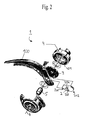
- FIG 2 is a drive for a seat adjustment device Serving step switch 1 isolated in an exploded view shown, based on which the operating principle the step switch 1 is illustrated.
- the drive lever 100, the tilting element 2, the holding plate 3 and the drive element 4 with an internal toothing 401 support a spacer sleeve 5, which is arranged along a drive axis 6 is.
- the tilting element 2 has two symmetrically arranged ones toothed areas 201, 202 lying around a circumference depending on the direction of drive one of the toothing areas 201, 202 with the locking elements 401 of the drive element 4 can be brought into engagement.
- On the axis of symmetry of the tilting elements 2 are two in relation to the drive axis 6 radially spaced bearing points arranged above the tilting element 2 on the one hand with the drive lever 100 and is also connected to the holding plate 3.
- the Bearing point between rocker 2 and drive lever 1 is thereby realized by a pin or pin 204, which in a corresponding recess of the drive lever 100 engages.
- the bearing point between the Holding plate 3 and the tilting element 2 by a pin or Pin of the holding plate 3 is formed, which in a hole 203rd of the tilting element 2 engages.
- the tilt element 2 becomes the zero point position, for example tilted to the left so that the toothing area 201 with the toothing 401 of the drive element 4 in Intervention occurs. In this way, a rotational movement of the Transfer the drive lever 100 to the drive element 4.
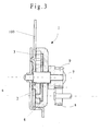
- FIG. 3 shows a section through an indexing device 1 with a drive lever pivotable about the drive axis 6 100 and a holding plate 3 on which a tilting element 2 is stored.
- the tilting element 2 is also with the Drive lever 100 connected and engages when twisted in the drive element 4, the non-positive or positive is connected to the shaft 7 and on this the rotary movement transmits.
- On the shaft 7 is a pinion 9, for example by pressing on or via a multi-tooth connection attached and by means of a deformation element or a Rivet connection fixed axially.
- the pinion 9 meshes one Gear stage 8, the rotational movement or the torque to the self-locking transmission 10, not shown transmits.
- the shaft 7 is eccentric arranged to the drive axis 6 and carries a spur gear 13, which is in an internal toothing 14 of an output ring gear 40 engages.
- the output ring gear 40 is driven by the rotary movement the spur gear 13 driven and in turn rotates the output shaft 11, the one to be adjusted, not shown seat component connected as an adjusting device is.
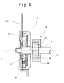
- Fig. 5 shows an embodiment of a coupling between a stepping mechanism 1 and an eccentric gear 10, at which to the drive element 4 directly to an eccentric the spur gear 13 arranged on the drive axle 6 is formed, that meshes with an internal toothing 14 and together with the Output ring gear 40 forms an eccentric gear 10.
Landscapes
- Engineering & Computer Science (AREA)
- Aviation & Aerospace Engineering (AREA)
- Transportation (AREA)
- Mechanical Engineering (AREA)
- Chairs For Special Purposes, Such As Reclining Chairs (AREA)
- Seats For Vehicles (AREA)
- Connection Of Motors, Electrical Generators, Mechanical Devices, And The Like (AREA)
- Transmission Devices (AREA)
Applications Claiming Priority (2)
| Application Number | Priority Date | Filing Date | Title |
|---|---|---|---|
| DE19855004 | 1998-11-20 | ||
| DE19855004A DE19855004C5 (de) | 1998-11-20 | 1998-11-20 | Antrieb für Verstellvorrichtungen in Kraftfahrzeugen |
Publications (2)
| Publication Number | Publication Date |
|---|---|
| EP1002691A2 true EP1002691A2 (fr) | 2000-05-24 |
| EP1002691A3 EP1002691A3 (fr) | 2002-04-24 |
Family
ID=7889363
Family Applications (1)
| Application Number | Title | Priority Date | Filing Date |
|---|---|---|---|
| EP99250393A Withdrawn EP1002691A3 (fr) | 1998-11-20 | 1999-11-04 | Entraínement pour dispositifs de réglage de véhicules automobiles |
Country Status (3)
| Country | Link |
|---|---|
| US (1) | US6283886B1 (fr) |
| EP (1) | EP1002691A3 (fr) |
| DE (1) | DE19855004C5 (fr) |
Cited By (5)
| Publication number | Priority date | Publication date | Assignee | Title |
|---|---|---|---|---|
| DE10260548A1 (de) * | 2002-12-21 | 2004-07-08 | Keiper Gmbh & Co. Kg | Antrieb mit Schubelement für einen Fahrzeugsitzeinsteller |
| DE10355821A1 (de) * | 2003-11-28 | 2005-06-30 | Keiper Gmbh & Co. Kg | Antrieb für einen Fahrzeugsitzeinsteller |
| US7114778B2 (en) | 2002-12-21 | 2006-10-03 | Keiper Gmbh & Co. Kg | Drive having a sliding element for a vehicle seat adjuster |
| US7201079B2 (en) | 2003-09-05 | 2007-04-10 | Keiper Gmbh & Co. Kg | Rotary actuator for an adjuster of a vehicle seat |
| WO2013010888A3 (fr) * | 2011-07-20 | 2013-06-06 | C. Rob. Hammerstein Gmbh & Co. Kg | Dispositif de réglage d'un siège de véhicule à moteur |
Families Citing this family (32)
| Publication number | Priority date | Publication date | Assignee | Title |
|---|---|---|---|---|
| GB2354284A (en) * | 1999-09-14 | 2001-03-21 | Johnson Controls Gmbh | A lever operated rotary drive mechanism for a reclining seat |
| DE19944866B8 (de) * | 1999-09-18 | 2008-05-29 | C. Rob. Hammerstein Gmbh & Co. Kg | Verstellvorrichtung für einen Kraftfahrzeugsitz |
| DE19952633C1 (de) | 1999-10-21 | 2001-09-13 | Brose Fahrzeugteile | Beidseitig wirkender Antrieb für Verstellvorrichtungen in Kraftfahrzeugen |
| DE10061364C1 (de) * | 2000-12-09 | 2001-11-29 | Faurecia Autositze Gmbh & Co | Betätigungsvorrichtung für Kraftfahrzeugsitze |
| US6652031B2 (en) * | 2001-01-19 | 2003-11-25 | Intier Automotive Inc. | Recliner assembly having a shaft with an annular recess |
| DE10122586A1 (de) * | 2001-05-10 | 2002-11-28 | Brose Fahrzeugteile | Verfahren und Vorrichtung zur Bestimmung einer Position eines durch eine Antriebsvorrichtung verstellbaren Teils eines Kraftfahrzeugsitzes |
| DE10142830B4 (de) * | 2001-08-21 | 2004-07-15 | Brose Fahrzeugteile Gmbh & Co. Kg, Coburg | Antrieb für mindestens eine manuell betätigbare Verstelleinrichtung an einem Fahrzeugsitz |
| US6691851B2 (en) * | 2001-10-03 | 2004-02-17 | L & P Property Management Company | Apparatus and method for ratchet actuator |
| US20060117885A1 (en) * | 2001-12-21 | 2006-06-08 | Martin Robson | Actuator |
| US7069811B2 (en) * | 2002-03-08 | 2006-07-04 | C. Rob. Hammerstein Gmbh & Co. Kg | Actuation device of an adjusting unit for automotive vehicle seats |
| DE10238704B4 (de) * | 2002-03-08 | 2007-04-12 | C. Rob. Hammerstein Gmbh & Co. Kg | Betätigungsvorrichtung einer Verstelleinrichtung für Kraftfahrzeugsitze |
| US6910738B2 (en) | 2003-01-28 | 2005-06-28 | Fisher Dynamics Corporation | Device and method for assembling a recliner mechanism |
| US6890034B2 (en) | 2003-01-28 | 2005-05-10 | Fisher Dynamics Corporation | Compact recliner with locking cams |
| US6869143B2 (en) * | 2003-04-01 | 2005-03-22 | Bae Industries, Inc. | Recliner clutch mechanism for vehicle seat |
| US20050168034A1 (en) * | 2004-01-21 | 2005-08-04 | Scott Fast | Disc recliner with dual cams |
| US7025422B2 (en) * | 2004-03-11 | 2006-04-11 | Fisher Dynamics Corporation | Round recliner assembly with rear folding latch |
| US7097253B2 (en) * | 2004-03-11 | 2006-08-29 | Fisher Dynamics Corporation | Round recliner assembly with rear folding latch |
| US20060025270A1 (en) * | 2004-07-27 | 2006-02-02 | Van De Geer Bernardus W G | Constantly engaged rotary recliner mechanism |
| DE102006005499B4 (de) * | 2005-04-28 | 2014-03-27 | C. Rob. Hammerstein Gmbh & Co. Kg | Stellantrieb für einen Kraftfahrzeugsitz |
| US7878594B2 (en) * | 2006-03-10 | 2011-02-01 | Ntn Corporation | Seat reclining device |
| DE202007012685U1 (de) * | 2007-09-11 | 2009-02-12 | Brose Fahrzeugteile Gmbh & Co. Kommanditgesellschaft, Coburg | Taumelgetriebe |
| CN103140374B (zh) * | 2010-08-10 | 2016-10-05 | 约翰逊控股公司 | 具有调整装置的车辆座椅 |
| DE102010051791A1 (de) * | 2010-11-18 | 2012-05-24 | GM Global Technology Operations LLC | Einrichtung zum Betätigen einer Sitzlehnenverstellung |
| US9499071B2 (en) * | 2011-07-20 | 2016-11-22 | C. Rob. Hammerstein Gmbh & Co. Kg | Adjusting device for a motor vehicle seat, comprising at least one stop |
| DE102012001279A1 (de) * | 2012-01-25 | 2013-07-25 | Gm Global Technology Operations, Llc | Verstellvorrichtung, Kraftfahrzeugsitz, Kraftfahrzeug und Verfahren hierzu |
| US10130530B2 (en) * | 2015-12-21 | 2018-11-20 | Stephen C. Golden, JR. | Mechanism and apparatus for wheelchair reconfiguration |
| JP6703929B2 (ja) * | 2016-11-17 | 2020-06-03 | シロキ工業株式会社 | 減速装置 |
| JP2018199356A (ja) * | 2017-05-25 | 2018-12-20 | トヨタ紡織株式会社 | リフタ装置 |
| JP6984534B2 (ja) | 2018-04-27 | 2021-12-22 | トヨタ紡織株式会社 | リフタ装置 |
| JP6984535B2 (ja) * | 2018-04-27 | 2021-12-22 | トヨタ紡織株式会社 | リフタ装置 |
| DE102020127715B4 (de) | 2020-10-21 | 2024-05-29 | Valmet Automotive Oy | Vorrichtung zum Antreiben einer verstellbaren Fahrzeugkomponente |
| CN222439882U (zh) * | 2024-01-19 | 2025-02-07 | 上海飞智电子科技有限公司 | 摇杆装置 |
Citations (1)
| Publication number | Priority date | Publication date | Assignee | Title |
|---|---|---|---|---|
| DE19653722A1 (de) | 1996-12-10 | 1998-07-23 | Brose Fahrzeugteile | Verstellvorrichtung |
Family Cites Families (29)
| Publication number | Priority date | Publication date | Assignee | Title |
|---|---|---|---|---|
| US2746331A (en) | 1954-08-11 | 1956-05-22 | Andersen Harold | Reversible ratchet wrench with supplementary drive means |
| US2995226A (en) * | 1959-05-07 | 1961-08-08 | Electrical Engineering & Mfg C | Reverse torque lock mechanism |
| US3008765A (en) * | 1959-08-24 | 1961-11-14 | Young Spring & Wire Corp | Reclining seat for two-door automobiles |
| DE1925778C3 (de) * | 1969-05-21 | 1975-03-13 | Fa. Fritz Keiper, 5630 Remscheid | Betätigungseinrichtung für eine Ver- und Feststellvorrichtung zum Einstellen von Teilen von Sitzen, insbesondere von Kraftfahrzeugsitzen |
| DE1926257A1 (de) * | 1969-05-22 | 1970-11-26 | Gierlinger Franz X | Tuerwinkel- und Zapfenband |
| DE3115942A1 (de) * | 1981-04-22 | 1982-11-18 | Audi Nsu Auto Union Ag, 7107 Neckarsulm | Einrichtung zum verstellen der rueckenlehne eines kraftfahrzeugsitzes |
| DE3533960A1 (de) * | 1985-09-24 | 1987-04-02 | Selzer Fertigungstech | Gelenkbeschlag fuer sitze mit verstellbarer lehne, insbesondere kraftfahrzeugsitze |
| DE3715726A1 (de) * | 1987-02-17 | 1988-12-01 | Burger Soehne | Handhebelbetaetigtes schrittschaltwerk fuer vorwaerts- und rueckwaertsschwenkschritte in variabler folge |
| DE3734363A1 (de) * | 1987-10-10 | 1989-04-20 | Burger Soehne | Vorrichtung zum verstellen eines kraftfahrzeugsitzes |
| DE3914056C1 (en) * | 1989-04-28 | 1990-08-09 | Skf Gmbh, 8720 Schweinfurt, De | Roller bearing cage assembly - involves cage with protuberance on one end fitting into cavity in other end |
| EP0450324B1 (fr) * | 1990-03-16 | 1994-07-20 | C. Rob. Hammerstein GmbH | Engrenage oscillant pour un siège réglable de véhicule |
| DE4120617C2 (de) | 1990-10-30 | 1994-06-01 | Brose Fahrzeugteile | Sperrkupplung mit einem abtriebsseitigen und einem antriebsseitigen Kupplungsabschnitt |
| JPH05176819A (ja) | 1991-12-27 | 1993-07-20 | Tokyo Seat Kk | 車両用シートのリクライニング装置 |
| DE4321335C2 (de) * | 1993-06-26 | 1997-06-05 | Daimler Benz Ag | Verstellvorrichtung |
| GB2288729A (en) * | 1994-04-30 | 1995-11-01 | Rentrop Hubbert & Wagner | Adjustment of a vehicle seat backrest |
| DE4437073A1 (de) * | 1994-07-01 | 1996-01-04 | Hammerstein Gmbh C Rob | Gelenkbeschlag für einen verstellbaren Fahrzeugsitz |
| DE4436096C2 (de) * | 1994-10-10 | 1998-02-26 | Keiper Recaro Gmbh Co | Klinkenschaltwerk zum Antrieb einer Verstellvorrichtungen für einen Fahrzeugsitz |
| DE4446741B4 (de) * | 1994-12-24 | 2004-06-24 | Adam Opel Ag | Betätigungseinrichtung |
| DE19500914A1 (de) * | 1995-01-13 | 1996-07-18 | Hammerstein Gmbh C Rob | Taumelgelenkbeschlag für einen verstellbaren Fahrzeugsitz |
| WO1996023672A1 (fr) | 1995-02-03 | 1996-08-08 | Brose Fahrzeugteile Gmbh & Co. Kommanditgesellschaft | Mecanisme manuel d'entrainement bidirectionnel servant a generer un mouvement de rotation |
| DE19527912C2 (de) * | 1995-02-03 | 1998-01-29 | Brose Fahrzeugteile | Beidseitig wirkender, manueller Antrieb zur Erzeugung einer Drehbewegung, insbesondere für Kraftfahrzeugsitze |
| FR2731256B1 (fr) * | 1995-03-01 | 1997-05-09 | Faure Bertrand Equipements Sa | Mecanisme de commande d'un organe rotatif au moyen d'une poignee pivotante, et siege equipe d'un tel mecanisme |
| DE19518424C2 (de) * | 1995-05-19 | 1998-11-26 | Joerg Schwarzbich | Verstellmechanismus |
| JP3077886B2 (ja) | 1995-07-19 | 2000-08-21 | 池田物産株式会社 | 両側リクライニング装置 |
| DE19540631C2 (de) * | 1995-10-31 | 2001-06-07 | Hammerstein Gmbh C Rob | Selbstsperrende Schrittschaltmechanik für eine Verstellvorrichtung eines Fahrzeugsitzes |
| DE19547513C1 (de) * | 1995-12-19 | 1997-06-12 | Faure Bertrand Sitztech Gmbh | Verstellvorrichtung für Kraftfahrzeugsitze |
| FR2743764B1 (fr) | 1996-01-22 | 1998-04-03 | Faure Bertrand Equipements Sa | Mecanisme d'articulation pour siege de vehicule, et siege comportant un tel mecanisme |
| FR2750186B1 (fr) | 1996-06-21 | 1998-08-28 | Faure Bertrand Equipements Sa | Mecanisme de commande d'un organe rotatif au moyen d'une poignee pivotante, et siege equipe d'un tel mecanisme |
| DE19734536C2 (de) * | 1997-07-30 | 1999-10-28 | Brose Fahrzeugteile | Taumelgetriebe für eine Fahrzeugsitz-Verstelleinrichtung |
-
1998
- 1998-11-20 DE DE19855004A patent/DE19855004C5/de not_active Expired - Fee Related
-
1999
- 1999-11-04 EP EP99250393A patent/EP1002691A3/fr not_active Withdrawn
- 1999-11-18 US US09/442,678 patent/US6283886B1/en not_active Expired - Fee Related
Patent Citations (1)
| Publication number | Priority date | Publication date | Assignee | Title |
|---|---|---|---|---|
| DE19653722A1 (de) | 1996-12-10 | 1998-07-23 | Brose Fahrzeugteile | Verstellvorrichtung |
Cited By (8)
| Publication number | Priority date | Publication date | Assignee | Title |
|---|---|---|---|---|
| DE10260548A1 (de) * | 2002-12-21 | 2004-07-08 | Keiper Gmbh & Co. Kg | Antrieb mit Schubelement für einen Fahrzeugsitzeinsteller |
| US7114778B2 (en) | 2002-12-21 | 2006-10-03 | Keiper Gmbh & Co. Kg | Drive having a sliding element for a vehicle seat adjuster |
| DE10260548B4 (de) * | 2002-12-21 | 2009-02-26 | Keiper Gmbh & Co.Kg | Antrieb für einen Fahrzeugsitzeinsteller |
| US7201079B2 (en) | 2003-09-05 | 2007-04-10 | Keiper Gmbh & Co. Kg | Rotary actuator for an adjuster of a vehicle seat |
| DE10355821A1 (de) * | 2003-11-28 | 2005-06-30 | Keiper Gmbh & Co. Kg | Antrieb für einen Fahrzeugsitzeinsteller |
| DE10355821B4 (de) * | 2003-11-28 | 2005-12-01 | Keiper Gmbh & Co.Kg | Antrieb für einen Fahrzeugsitzeinsteller |
| WO2013010888A3 (fr) * | 2011-07-20 | 2013-06-06 | C. Rob. Hammerstein Gmbh & Co. Kg | Dispositif de réglage d'un siège de véhicule à moteur |
| DE112012003011B4 (de) * | 2011-07-20 | 2020-06-10 | Adient Luxembourg Holding S.À R.L. | Verstellvorrichtung für einen Kraftfahrzeugsitz |
Also Published As
| Publication number | Publication date |
|---|---|
| DE19855004C2 (de) | 2001-02-08 |
| US6283886B1 (en) | 2001-09-04 |
| DE19855004C5 (de) | 2006-12-28 |
| DE19855004A1 (de) | 2000-06-08 |
| EP1002691A3 (fr) | 2002-04-24 |
Similar Documents
| Publication | Publication Date | Title |
|---|---|---|
| DE19855004C2 (de) | Antrieb für Verstellvorrichtungen in Kraftfahrzeugen | |
| EP0751032B1 (fr) | Dispositif de réglage | |
| EP0988171B1 (fr) | Mécanisme de commande de réglage agissant sur deux côtés | |
| DE102017100934B4 (de) | Getriebeanordnung für eine Sitzverstellung | |
| EP0930983B1 (fr) | Dispositif de réglage pour siège de véhicule | |
| DE60021847T2 (de) | Vorrichtung zum Verstellen der Rückenlehneneigung eines Kraftfahrzeugsitzes | |
| DE3723204C2 (de) | Verstellvorrichtung für einen Sitz, insbesondere Kraftfahrzeugsitz, zur Neigungseinstellung der Rückenlehne | |
| DE102011075183A1 (de) | Verstellantrieb für eine Verstelleinrichtung eines Kraftfahrzeugsitzes | |
| DE10126327B4 (de) | Antriebseinheit | |
| EP1116902B1 (fr) | Dispositif de commande d'une boíte de vitesses | |
| DE3804352A1 (de) | Verstellvorrichtung fuer sitze | |
| DE19734536C2 (de) | Taumelgetriebe für eine Fahrzeugsitz-Verstelleinrichtung | |
| DE19956984A1 (de) | Fahrzeugsitz mit Gelenkmechanismus | |
| EP1244880B1 (fr) | Dispositif d'ajustement a train d'engrenage planetaire | |
| EP1128979B1 (fr) | Entrainement de dispositif de reglage de la hauteur pour un siege de vehicule | |
| DE4023824C2 (de) | Fahrzeugsitz | |
| DE3605895A1 (de) | Sitzlehnenverstellmechanismus | |
| DE68910890T2 (de) | Mechanismus und dessen arbeitsweise zum positionieren eines gangschalthebels in parkstellung. | |
| DE3729134A1 (de) | Gelenkbeschlag fuer einen fahrzeugsitz | |
| DE3541760A1 (de) | Rueckwaertsneigungswinkel-einstelleinrichtung | |
| DE202007003713U1 (de) | Vorrichtung zum Verstellen von Sitzelementen | |
| DE3234257A1 (de) | Sitzlehnenverstellvorrichtung | |
| DE3321635C2 (fr) | ||
| DE19546433C1 (de) | Stelleinrichtung für Sitze, insbesondere Fahrzeugsitze | |
| DE10142830A1 (de) | Antrieb für manuell betätigbare Verstelleinrichtungen an Fahrzeugsitzen |
Legal Events
| Date | Code | Title | Description |
|---|---|---|---|
| PUAI | Public reference made under article 153(3) epc to a published international application that has entered the european phase |
Free format text: ORIGINAL CODE: 0009012 |
|
| AK | Designated contracting states |
Kind code of ref document: A2 Designated state(s): AT BE CH CY DE DK ES FI FR GB GR IE IT LI LU MC NL PT SE |
|
| AX | Request for extension of the european patent |
Free format text: AL;LT;LV;MK;RO;SI |
|
| PUAL | Search report despatched |
Free format text: ORIGINAL CODE: 0009013 |
|
| AK | Designated contracting states |
Kind code of ref document: A3 Designated state(s): AT BE CH CY DE DK ES FI FR GB GR IE IT LI LU MC NL PT SE |
|
| AX | Request for extension of the european patent |
Free format text: AL;LT;LV;MK;RO;SI |
|
| AKX | Designation fees paid | ||
| REG | Reference to a national code |
Ref country code: DE Ref legal event code: 8566 |
|
| STAA | Information on the status of an ep patent application or granted ep patent |
Free format text: STATUS: THE APPLICATION IS DEEMED TO BE WITHDRAWN |
|
| 18D | Application deemed to be withdrawn |
Effective date: 20021025 |