EP1002696B1 - Structure de montage pour diodes électroluminescentes - Google Patents
Structure de montage pour diodes électroluminescentes Download PDFInfo
- Publication number
- EP1002696B1 EP1002696B1 EP99122706A EP99122706A EP1002696B1 EP 1002696 B1 EP1002696 B1 EP 1002696B1 EP 99122706 A EP99122706 A EP 99122706A EP 99122706 A EP99122706 A EP 99122706A EP 1002696 B1 EP1002696 B1 EP 1002696B1
- Authority
- EP
- European Patent Office
- Prior art keywords
- light emitting
- emitting diode
- wire
- connecting member
- mounting structure
- Prior art date
- Legal status (The legal status is an assumption and is not a legal conclusion. Google has not performed a legal analysis and makes no representation as to the accuracy of the status listed.)
- Expired - Lifetime
Links
Images



Classifications
-
- B—PERFORMING OPERATIONS; TRANSPORTING
- B60—VEHICLES IN GENERAL
- B60Q—ARRANGEMENT OF SIGNALLING OR LIGHTING DEVICES, THE MOUNTING OR SUPPORTING THEREOF OR CIRCUITS THEREFOR, FOR VEHICLES IN GENERAL
- B60Q1/00—Arrangement of optical signalling or lighting devices, the mounting or supporting thereof or circuits therefor
- B60Q1/26—Arrangement of optical signalling or lighting devices, the mounting or supporting thereof or circuits therefor the devices being primarily intended to indicate the vehicle, or parts thereof, or to give signals, to other traffic
- B60Q1/2696—Mounting of devices using LEDs
-
- F—MECHANICAL ENGINEERING; LIGHTING; HEATING; WEAPONS; BLASTING
- F21—LIGHTING
- F21V—FUNCTIONAL FEATURES OR DETAILS OF LIGHTING DEVICES OR SYSTEMS THEREOF; STRUCTURAL COMBINATIONS OF LIGHTING DEVICES WITH OTHER ARTICLES, NOT OTHERWISE PROVIDED FOR
- F21V29/00—Protecting lighting devices from thermal damage; Cooling or heating arrangements specially adapted for lighting devices or systems
- F21V29/50—Cooling arrangements
- F21V29/502—Cooling arrangements characterised by the adaptation for cooling of specific components
- F21V29/503—Cooling arrangements characterised by the adaptation for cooling of specific components of light sources
-
- B—PERFORMING OPERATIONS; TRANSPORTING
- B60—VEHICLES IN GENERAL
- B60Q—ARRANGEMENT OF SIGNALLING OR LIGHTING DEVICES, THE MOUNTING OR SUPPORTING THEREOF OR CIRCUITS THEREFOR, FOR VEHICLES IN GENERAL
- B60Q1/00—Arrangement of optical signalling or lighting devices, the mounting or supporting thereof or circuits therefor
- B60Q1/26—Arrangement of optical signalling or lighting devices, the mounting or supporting thereof or circuits therefor the devices being primarily intended to indicate the vehicle, or parts thereof, or to give signals, to other traffic
- B60Q1/30—Arrangement of optical signalling or lighting devices, the mounting or supporting thereof or circuits therefor the devices being primarily intended to indicate the vehicle, or parts thereof, or to give signals, to other traffic for indicating rear of vehicle, e.g. by means of reflecting surfaces
- B60Q1/305—Indicating devices for towed vehicles
-
- F—MECHANICAL ENGINEERING; LIGHTING; HEATING; WEAPONS; BLASTING
- F21—LIGHTING
- F21S—NON-PORTABLE LIGHTING DEVICES; SYSTEMS THEREOF; VEHICLE LIGHTING DEVICES SPECIALLY ADAPTED FOR VEHICLE EXTERIORS
- F21S43/00—Signalling devices specially adapted for vehicle exteriors, e.g. brake lamps, direction indicator lights or reversing lights
- F21S43/10—Signalling devices specially adapted for vehicle exteriors, e.g. brake lamps, direction indicator lights or reversing lights characterised by the light source
- F21S43/13—Signalling devices specially adapted for vehicle exteriors, e.g. brake lamps, direction indicator lights or reversing lights characterised by the light source characterised by the type of light source
- F21S43/14—Light emitting diodes [LED]
-
- F—MECHANICAL ENGINEERING; LIGHTING; HEATING; WEAPONS; BLASTING
- F21—LIGHTING
- F21S—NON-PORTABLE LIGHTING DEVICES; SYSTEMS THEREOF; VEHICLE LIGHTING DEVICES SPECIALLY ADAPTED FOR VEHICLE EXTERIORS
- F21S43/00—Signalling devices specially adapted for vehicle exteriors, e.g. brake lamps, direction indicator lights or reversing lights
- F21S43/10—Signalling devices specially adapted for vehicle exteriors, e.g. brake lamps, direction indicator lights or reversing lights characterised by the light source
- F21S43/19—Attachment of light sources or lamp holders
- F21S43/195—Details of lamp holders, terminals or connectors
-
- H—ELECTRICITY
- H01—ELECTRIC ELEMENTS
- H01R—ELECTRICALLY-CONDUCTIVE CONNECTIONS; STRUCTURAL ASSOCIATIONS OF A PLURALITY OF MUTUALLY-INSULATED ELECTRICAL CONNECTING ELEMENTS; COUPLING DEVICES; CURRENT COLLECTORS
- H01R4/00—Electrically-conductive connections between two or more conductive members in direct contact, i.e. touching one another; Means for effecting or maintaining such contact; Electrically-conductive connections having two or more spaced connecting locations for conductors and using contact members penetrating insulation
- H01R4/24—Connections using contact members penetrating or cutting insulation or cable strands
- H01R4/2416—Connections using contact members penetrating or cutting insulation or cable strands the contact members having insulation-cutting edges, e.g. of tuning fork type
- H01R4/2445—Connections using contact members penetrating or cutting insulation or cable strands the contact members having insulation-cutting edges, e.g. of tuning fork type the contact members having additional means acting on the insulation or the wire, e.g. additional insulation penetrating means, strain relief means or wire cutting knives
- H01R4/245—Connections using contact members penetrating or cutting insulation or cable strands the contact members having insulation-cutting edges, e.g. of tuning fork type the contact members having additional means acting on the insulation or the wire, e.g. additional insulation penetrating means, strain relief means or wire cutting knives the additional means having two or more slotted flat portions
- H01R4/2454—Connections using contact members penetrating or cutting insulation or cable strands the contact members having insulation-cutting edges, e.g. of tuning fork type the contact members having additional means acting on the insulation or the wire, e.g. additional insulation penetrating means, strain relief means or wire cutting knives the additional means having two or more slotted flat portions forming a U-shape with slotted branches
-
- F—MECHANICAL ENGINEERING; LIGHTING; HEATING; WEAPONS; BLASTING
- F21—LIGHTING
- F21S—NON-PORTABLE LIGHTING DEVICES; SYSTEMS THEREOF; VEHICLE LIGHTING DEVICES SPECIALLY ADAPTED FOR VEHICLE EXTERIORS
- F21S45/00—Arrangements within vehicle lighting devices specially adapted for vehicle exteriors, for purposes other than emission or distribution of light
- F21S45/40—Cooling of lighting devices
- F21S45/47—Passive cooling, e.g. using fins, thermal conductive elements or openings
-
- F—MECHANICAL ENGINEERING; LIGHTING; HEATING; WEAPONS; BLASTING
- F21—LIGHTING
- F21V—FUNCTIONAL FEATURES OR DETAILS OF LIGHTING DEVICES OR SYSTEMS THEREOF; STRUCTURAL COMBINATIONS OF LIGHTING DEVICES WITH OTHER ARTICLES, NOT OTHERWISE PROVIDED FOR
- F21V19/00—Fastening of light sources or lamp holders
- F21V19/001—Fastening of light sources or lamp holders the light sources being semiconductors devices, e.g. LEDs
-
- F—MECHANICAL ENGINEERING; LIGHTING; HEATING; WEAPONS; BLASTING
- F21—LIGHTING
- F21V—FUNCTIONAL FEATURES OR DETAILS OF LIGHTING DEVICES OR SYSTEMS THEREOF; STRUCTURAL COMBINATIONS OF LIGHTING DEVICES WITH OTHER ARTICLES, NOT OTHERWISE PROVIDED FOR
- F21V21/00—Supporting, suspending, or attaching arrangements for lighting devices; Hand grips
- F21V21/002—Supporting, suspending, or attaching arrangements for lighting devices; Hand grips making direct electrical contact, e.g. by piercing
-
- H—ELECTRICITY
- H01—ELECTRIC ELEMENTS
- H01R—ELECTRICALLY-CONDUCTIVE CONNECTIONS; STRUCTURAL ASSOCIATIONS OF A PLURALITY OF MUTUALLY-INSULATED ELECTRICAL CONNECTING ELEMENTS; COUPLING DEVICES; CURRENT COLLECTORS
- H01R33/00—Coupling devices specially adapted for supporting apparatus and having one part acting as a holder providing support and electrical connection via a counterpart which is structurally associated with the apparatus, e.g. lamp holders; Separate parts thereof
- H01R33/05—Two-pole devices
- H01R33/06—Two-pole devices with two current-carrying pins, blades or analogous contacts, having their axes parallel to each other
- H01R33/09—Two-pole devices with two current-carrying pins, blades or analogous contacts, having their axes parallel to each other for baseless lamp bulb
-
- H—ELECTRICITY
- H10—SEMICONDUCTOR DEVICES; ELECTRIC SOLID-STATE DEVICES NOT OTHERWISE PROVIDED FOR
- H10H—INORGANIC LIGHT-EMITTING SEMICONDUCTOR DEVICES HAVING POTENTIAL BARRIERS
- H10H20/00—Individual inorganic light-emitting semiconductor devices having potential barriers, e.g. light-emitting diodes [LED]
- H10H20/80—Constructional details
- H10H20/85—Packages
- H10H20/857—Interconnections, e.g. lead-frames, bond wires or solder balls
-
- Y—GENERAL TAGGING OF NEW TECHNOLOGICAL DEVELOPMENTS; GENERAL TAGGING OF CROSS-SECTIONAL TECHNOLOGIES SPANNING OVER SEVERAL SECTIONS OF THE IPC; TECHNICAL SUBJECTS COVERED BY FORMER USPC CROSS-REFERENCE ART COLLECTIONS [XRACs] AND DIGESTS
- Y10—TECHNICAL SUBJECTS COVERED BY FORMER USPC
- Y10S—TECHNICAL SUBJECTS COVERED BY FORMER USPC CROSS-REFERENCE ART COLLECTIONS [XRACs] AND DIGESTS
- Y10S362/00—Illumination
- Y10S362/80—Light emitting diode
Definitions
- the present invention relates to a light emitting diode mounting structure, and more particularly to a light emitting diode mounting structure that is suitable for application to a vehicular lamp.
- the leads of a light emitting diode used in such applications as vehicular lamps are soldered to a printed circuit board that is provided on the lamp, according to, for example, the disclosure of the Japanese laid-open patent application publication H10-188614 .
- each of the leads of the light emitting diode is soldered to the printed circuit board individually, the process of mounting the light emitting diode to the board is troublesome, and manufacturing efficiency is poor.
- the process of removing leads from their positions on the printed circuit board and resoldering leads is complex.
- a light emitting diode mounting structure is known from JP 10-208515 .
- This prior art discloses a wiring member, which is disposed in the inside of a fixture body and its surface is used as a LED mounting surface.
- the wiring member has small holes into each of which a locking part is inserted, thereby locking the LED to the wiring member.
- a surface part having a surface area capable of reflecting the light of the light emitting diode is formed on the metal connecting member. For this reason, the light usage efficiency of the light emitting diode is improved, the result being that a smaller number of light emitting diodes can be used to achieve the required brightness, thereby simplifying the structure and reducing the cost.
- the above-noted light emitting diode can also have four leads, these leads being engaged with two metal connecting member that are disposed in proximity.
- the light emitting diode does not tend to bend over and does not tend to change its direction after mounting. Additionally, because two metal connecting members are used to mount one light emitting diode, the size of one metal plate can be made small, thereby facilitating manufacture of the metal connecting members. Additionally, because the two metal connecting members are in mutual proximity, there is little affect on the rate of usage of the light.
- the lead can be formed of a metal that has a thermal conductivity that is equivalent to or greater than that of copper.
- the lead is formed of a metal having a thermal conductivity that is equivalent to or greater than of copper, heat that is generated by the light emitting diode is reliably transmitted via the lead to the metal connecting member, where it is radiated from the surface part thereof. There is thus an improvement in the heat radiation of the light emitting diode.
- the wire can be formed by an insulation covering and a center conductor disposed within the insulation cover, and the metal connecting member can be formed by a foot part that faces the housing, and a cutting groove part that is formed in the end of the foot part.
- the cutting groove cuts the insulation covering of the wire, and eats thereinto, the effect being that the metal connecting member comes into a conductive connection with the center conductor, and holds the wire in place.
- a cutting groove formed in the foot part of the metal connecting member cuts the insulation covering of the wire and bites into the inside thereof so that an electrical connection is made to the center conductor, the biting force between the cutting groove and the wire also serving to hold the light emitting diode in one operation to the wire. For this reason, it is not necessary to perform a soldering operation to mount the light emitting diode in place, and it easy to replace the light emitting diode. Additionally, because it is possible to use the surface part of the metal connecting member as a surface for an operator to press with a finger, the operation of pressing the metal connecting member to press the wire into the cutting groove is facilitated.
- the surface part of the metal connecting member can also be a surface that is colored with a metallic coloring.
- the connecting member because of the connecting member that is mounted to a holder engaged with the housing, the connecting member is securely held to the housing. Because the light emitting diode is resiliently grabbed and supported by the clip part of the connecting member, it is held in place with respect to the housing. As a result, the light emitting diode is held securely to the housing, thereby resulting in a stable light axis. Because the light axis of the light emitting diode is stabilized in this manner, there is an improvement in the usage of the light thereof. For this reason, the number of light emitting diodes required to achieve the desired brightness is reduced, thereby simplifying the structure and reducing the cost.
- the cutting groove formed in the foot part of the connecting member bites into the inside of the wire insulation covering, the biting force between the cutting groove and the wire holds the wire in place with a single operation. Additionally, it is possible to hold the light emitting diode in place by inserting the wire into the clip part, thereby eliminating the need of a soldering operation to hold the lead in place, thereby simplifying the mounting task. This not only improves manufacturing efficiency and enables automation thereof, but also facilitates replacement of the light emitting diode.
- the light emitting diode can have four leads, the holder can have two neighboring connecting members mounted to it, and each connecting member can have two clip parts. It is also possible for each of the connecting members to have two cutting grooves. The four leads are each grabbed and supported by the clip parts.
- the clip parts can be exposed from the holder, in which case because of the exposure of the clip parts from the holder heat generated by the light emitting diode is radiated from the clip parts, thereby improving the heat radiation performance of the light emitting diode.
- the leads can be formed of a metal that has a thermal conductivity equivalent to or greater than that of copper.
- the leads are made of a metal that has a thermal conductivity equivalent to or greater than that of copper, heat generated by the light emitting diode is reliably transmitted to the metal plates via the leads, and is radiated from the clip parts. There is therefore a further improvement in the heat radiation performance of the light emitting diode.
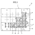
- Fig. 1 through Fig. 4 illustrate the first embodiment of the present invention. This embodiment will be described with regard to application to a vehicular stop lamp.
- a housing 1 is provided on the inside of a lens 18 of a stop lamp 19.
- the stop lamp 19 (lens 18), as shown in Fig. 2, has a three-dimensional shape that is continuous with the outside contour of the surface of the vehicle.
- the housing 1 has a plurality of mounting surfaces 1a that are disposed in three-dimensionally skewed levels so as to follow the shape of the stop lamp 19.
- Two wires 2 are disposed in parallel so as to pass each mounting surface 1a.
- a light emitting diode 3 is mounted to the wires 2.
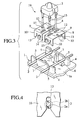
- the wires 2 are each formed by a center conductor 2a and an insulation covering 2b. Because each of the mounting structures for the light emitting diodes on the mounting surfaces 1a is substantially the same, the description below is provided for only one exemplary mounting surface 1a, based on Fig. 3.
- two walls 4 are formed on the mounting surface 2a so as to face each other.
- the wires 2 are fitted into the cutouts 5 that are formed at the upper edges of the walls 4.
- a base 6 for supporting the wires 2 is formed at the bottom side of the cut-outs 5.
- a rib 7 for improving rigidity is formed at the center of each wall 4.
- a metal plate 8 is formed by a surface part 9, and foot parts 10 formed by bending the ends the surface part 9 toward the mounting surface 1a.
- the part of the surface part 9 that is covered by the light emitting diode 3 supports the light emitting diode 3.
- the part of the surface part 9 that is not covered by the light emitting diode 3 is exposed in a wide area at the outside of the side of the light emitting diode 3, and reflects light from the light emitting diode 3. That is, the surface part 9 has a surface area that can reflect light from the light emitting diode 3.
- the surface part 9 has a highly reflective metallic (silver) color imparted to it.
- a downwardly open groove 13 and a outwardly open partially cut tab 14 are formed in the ends of the foot parts 10.
- the light emitting diode 3 has leads 15 at each of its four corners.
- the leads 15 are formed of copper, which has good thermal conductivity.
- the leads 15 of the light emitting diode 3 are inserted into the slits 12 of each of the metal plates 8.
- the cutting grooves 13 of the metal plates 8 are set over the wires 2, and the surface parts 9 of the metal plates 8 are pressed so as to push the cutting grooves 13 over the wires 2. Because of the surface parts 9 in the area surrounding the light emitting diode 3, it is possible to use this surface part 9 as a surface to press with the finger, thereby facilitating the task of pressing the metal plates 8 over the wires 2.
- the cutting grooves 13 When the cutting grooves 13 are pressed over the wires 2, the cutting grooves 13 cut the insulation covering 2b of the wires 2, and bite into the inside thereof, thereby making an electrical connection with respect to the center conductors 2a of the wires 2 (refer to Fig. 4).
- the biting force between the cutting grooves 13 and the wires 2 holds the light emitting diode 3 in place over the wires 2, and there is an electrically conductive connection via the metal plates 8 between the light emitting diode 3 an the wires 2. Because the wires 2 are supported from the bottom by the bases 6, there is a secure pressure pushing the cutting groove onto the wires 2.
- the foot parts 10 of the metal plates 8 fit between the mutually opposing walls 4, and the bent partial cutouts 14 on the foot parts 10 thereof make a resilient connection with the walls 4. For this reason, movement with respect to the mounting position of the metal plates 8 is restricted, so that the metal plates 8 are held securely and stably in place.
- the mounted light emitting diode 3 has four leads 15, it does not bend over after mounting, so that there is no tendency for the orientation of the light emitting diode 3 to change after mounting. Additionally, because a single light emitting diode 3 is held in place by two metal plates 8, it is possible to make the size of each metal plat 8 small, thereby simplifying the manufacture of the metal plates 8.
- the light of the mounted light emitting diode 3 is reliably reflected by the surface part 9 of the metal plate 8, which has had a metallic coloring imparted thereto, the result being an improvement in the usage of light from the light emitting diode 3. Therefore, for a given brightness the number of light emitting diodes 3 required is reduced, thereby simplifying the lamp structure and reducing the cost.
- the light emitting diode 3 is supported by two metal plates 8, which are disposed in mutual proximity and have substantially the same shape, thereby improving the efficiency of usage of the light.
- the leads 15 of the light emitting diode 3 are made of copper, which has a high thermal conductivity, heat generated from the light emitting diode 3 is reliably transmitted to the metal plates 8 via the leads 15, and is radiated from the broad surface parts 9 thereof, thereby improving the radiation of heat from the light emitting diode 3.
- the housing 1 has a plurality of mounting surfaces 1a has a plurality of mounting surfaces 1a that are disposed in three-dimensionally skewed levels so as to follow the shape of the stop lamp 19, with the light emitting diodes 3 disposed on each mounting surface 1a.
- a housing 21 is provided on the inside of a lens 38 of a vehicular stop lamp 39.
- the stop lamp 39 (lens 38) has a three-dimensional shape that follows the shape of the body of the vehicle. For this reason, the housing 21 has a plurality of mounting surfaces 1a that are disposed in three-dimensionally skewed levels so as to follow the shape of the stop lamp 39.
- Fig. 5 shows one of the plurality of mounting surfaces 21a.
- Two wires 2 are disposed on the mounting surface so as to be mutually parallel, and a light emitting diode 23 is mounted in place over the wires 2.
- the wires 2 each are formed by a center conductor 2a and an insulation covering 2b that covers the center conductor 2a.
- the holder 27 is made up of a center block 28, protrusions 29 that protrude from the surfaces at each side of the center blocks 28, and upper pieces 30 disposed at the top edges of the protrusions 29, these being integrally formed as a molded resin piece.
- the upper pieces 30 have formed in them a pair of insertion holes 31.
- the connecting members 32 are pressed from sheet metal, and two of these connecting members are mounted to one holder 27.
- the connecting members 32 have an integrally formed foot parts 34 with a cutting groove 33 in the ends thereof, and integrally formed clip parts 35 which are formed by bending back the sheet metal material.
- Four leads 36 extend from the four corners of the light emitting diode 3, these leads being formed from copper, which has good thermal conductivity.
- the holder 27 is inserted between the two walls 24.
- the upper pieces 30 of the holders 27 engage with the tabs 25 at the upper edges of the walls 24, so that the holder 27 is held in place with respect to the housing 12 with a single operation.
- the wires 2 are disposed between the bases 26 and the upper pieces 30.
- the connecting members 32 are mounted to the holder 27. More specifically, the clips 35 are pushed onto the protrusions 29 of the holder 27, so that the foot parts 34 are inserted into the insertion holes 31 of the upper pieces 30. The upper part of the foot parts 34 are hidden within the upper pieces 30 of the holder 27, but the clip parts 35 are totally exposed to outside the holder 27.
- the cutting grooves 33 in the ends of the foot parts 34 cut the insulation covering 2b of the wires 2, thereby biting into the insulation covering 2b so as to engage with the center conductor 2a therewithin (refer to Fig. 8). By doing this, an electrically conducting connection is made between the connecting members 32 and the wire 2.
- the biting force between the cutting grooves 33 and the wire 2 holds the connecting members 32 in place with respect to the holder 27.
- the wires 2 are supported from below by the bases 26, making is possible to perform the task of pressing into the cutting grooves 33.
- the four leads 36 of the light emitting diode 23 are each inserted into the clip parts 35 of each of the connecting members 32.
- the leads 36 are grabbed and held by these clip parts 35, so that the grabbing force of the clip parts 35 provides the holding force.
- the connecting members 32 are stably held to the mounting surface 21a of the housing 21, and the light emitting diode 23 is held in place with respect to the housing 21 by the action of the clip parts 35 of the connecting members 32 resiliently holding and supporting the leads 36 thereof. For this reason, the light emitting diode 23 is held securely in place with respect to the housing 21, and the light axis thereof is held stable. Because the light axis of the light emitting diode 23 is stabilized in this manner, there is an improvement in the usage of the light therefrom. For this reason, the number of light emitting diodes required to achieve the desired brightness is reduced in comparison with the related art, thereby simplifying the structure and reducing the cost.
- the clip parts 35 are totally exposed from the holder 27, heat generated from the light emitting diode 23 can be radiated from the clip parts 35, thereby improving the heat radiation performance of the light emitting diode 23.
- the leads 36 of the light emitting diode 23 are made of copper, which has a high thermal conductivity, heat generated by the light emitting diode 23 is reliably transmitted via the leads 36 to the connecting parts 32, thereby providing a further improvement in radiation of heat from the light emitting diode 23.
- the housing 21 has a plurality of mounting surfaces 21a that are disposed in three-dimensionally skewed levels so as to follow the shape of the stop lamp 39.
Landscapes
- Engineering & Computer Science (AREA)
- General Engineering & Computer Science (AREA)
- Mechanical Engineering (AREA)
- Physics & Mathematics (AREA)
- Microelectronics & Electronic Packaging (AREA)
- Optics & Photonics (AREA)
- Led Device Packages (AREA)
- Non-Portable Lighting Devices Or Systems Thereof (AREA)
- Arrangement Of Elements, Cooling, Sealing, Or The Like Of Lighting Devices (AREA)
Claims (12)
- Structure de montage pour diode électroluminescente comportant :une diode électroluminescente (3) ayant une sortie (15),
caractérisée parun élément de connexion en métal (8) fixé sur un fil (2) et relié à celui-ci sur un boîtier, la sortie (15) étant en contact avec l'élément de connexion en métal (8) de manière à être en connexion électrique avec celui-ci et étant supportée par celui-ci, etune partie de surface de l'élément de connexion en métal (8) ayant une aire de surface apte à réfléchir de la lumière provenant de la diode électroluminescente (3). - Structure de montage pour diode électroluminescente selon la revendication 1, dans laquelle la diode électroluminescente (3) comporte quatre sorties (15), et les sorties (15) sont en contact avec deux éléments de connexion en métal (8) disposés à proximité mutuelle.
- Structure de montage pour diode électroluminescente selon la revendication 1, dans laquelle la sortie (15) est formée d'un métal ayant une conductivité thermique équivalente à celle du cuivre ou supérieure à celle-ci.
- Structure de montage pour diode électroluminescente selon la revendication 1, dans laquelle le fil (2) comporte un revêtement d'isolation (2b) et un conducteur central (2a) disposé à l'intérieur du revêtement d'isolation (2b),
l'élément de connexion en métal (8) comporte une partie de pied (10) s'étendant en direction du boîtier à partir de la partie de surface et une rainure de coupe (13) formée sur l'extrémité de la partie de pied (10), et
lorsque le fil (2) est inséré dans la rainure de coupe (13), la rainure de coupe (13) coupe le revêtement d'isolation (2b) du fil (2) et mord dans l'intérieur de celui-ci, en formant un contact électriquement conducteur par rapport au conducteur central de celui-ci et en maintenant le fil (2) en place. - Structure de montage pour diode électroluminescente selon la revendication 1, dans laquelle la partie de surface de l'élément de connexion en métal (8) a une coloration métallique donnée à celle-ci.
- Structure de montage pour diode électroluminescente comportant :deux diodes électroluminescentes (3) ayant chacune une sortie (15),
caractérisée par,deux éléments de connexion en métal fixés sur un fil et reliés à celui-ci sur un boîtier, les sorties venant en contact avec des éléments respectifs de connexion en métal de manière à être en connexion électrique avec ceux-ci et étant supportées par ceux-ci, et les éléments de connexion en métal ayant chacun un trou (11) pour raccorder un fil de liaison (16) pour établir une connexion électrique entre les éléments de connexion en métal. - Structure de montage pour diode électroluminescente comportant :une diode électroluminescente (23) ayant une sortie (36),
caractérisée par,un support non métallique (27) en contact avec un boîtier, etun élément de connexion en métal (32) fixé sur un fil (2) et relié à celui-ci sur un boîtier, la sortie (36) étant en contact avec l'élément de connexion en métal (32) de manière à être en connexion électrique avec celui-ci et étant supportée par celui-ci, ledit élément de connexion en métal (32) étant monté sur le support (27), l'élément de connexion (32) ayant une partie de pied formée d'un seul tenant (34) et une partie de pince (35), la sortie (36) étant saisie dans la partie de pince (35) et étant supportée par celle-ci, la partie de pied (34) ayant une rainure de coupe (33) pour recevoir le fil (2) sur le boîtier, le fil (2) comportant un revêtement d'isolation (2b) et un conducteur central (2a) disposé à l'intérieur du revêtement d'isolation (2b), et lorsque le fil (2) est inséré dans la rainure de coupe (33), la rainure de coupe (33) découpant le revêtement d'isolation (2b) et mordant dans l'intérieur de celui-ci, en formant un contact électriquement conducteur entre l'élément de connexion (32) et le conducteur central (2a) et en maintenant le fil (2) en place. - Structure de montage pour diode électroluminescente selon la revendication 7, dans laquelle la diode électroluminescente (23) comporte quatre sorties (36), deux éléments de connexion (32) sont montés à proximité mutuelle du support (27), chaque élément de connexion (32) comporte deux parties de pinces (35), et les quatre sorties (36) sont chacune saisies et supportées par les parties de pinces (35).
- Structure de montage pour diode électroluminescente selon la revendication 8, dans laquelle chaque élément de connexion (32) comporte deux rainures de coupe (33).
- Structure de montage pour diode électroluminescente selon la revendication 7, dans laquelle la partie de pince (35) est exposée à partir du support (27).
- Structure de montage pour diode électroluminescente selon la revendication 10, dans laquelle la sortie (36) est formée d'un métal ayant une conductivité thermique équivalente à celle du cuivre ou supérieure à celle-ci.
- Lampe de véhicule comportant :un boîtier disposé à l'intérieur d'une lentille et comportant une pluralité de structures de montage selon la revendication 1 ou la revendication 7 disposées de manière à suivre un contour de la lentille.
Applications Claiming Priority (4)
| Application Number | Priority Date | Filing Date | Title |
|---|---|---|---|
| JP32694198 | 1998-11-17 | ||
| JP32694198A JP3807131B2 (ja) | 1998-11-17 | 1998-11-17 | 発光ダイオードの固定構造 |
| JP11004434A JP2000207922A (ja) | 1999-01-11 | 1999-01-11 | 発光ダイオ―ドの固定構造 |
| JP443499 | 1999-01-11 |
Publications (3)
| Publication Number | Publication Date |
|---|---|
| EP1002696A2 EP1002696A2 (fr) | 2000-05-24 |
| EP1002696A3 EP1002696A3 (fr) | 2002-05-02 |
| EP1002696B1 true EP1002696B1 (fr) | 2007-08-01 |
Family
ID=26338194
Family Applications (1)
| Application Number | Title | Priority Date | Filing Date |
|---|---|---|---|
| EP99122706A Expired - Lifetime EP1002696B1 (fr) | 1998-11-17 | 1999-11-15 | Structure de montage pour diodes électroluminescentes |
Country Status (3)
| Country | Link |
|---|---|
| US (2) | US6386733B1 (fr) |
| EP (1) | EP1002696B1 (fr) |
| DE (1) | DE69936704T2 (fr) |
Families Citing this family (132)
| Publication number | Priority date | Publication date | Assignee | Title |
|---|---|---|---|---|
| GB2330679B (en) | 1997-10-21 | 2002-04-24 | 911 Emergency Products Inc | Warning signal light |
| US6462669B1 (en) | 1999-04-06 | 2002-10-08 | E. P . Survivors Llc | Replaceable LED modules |
| WO2000074972A1 (fr) * | 1999-06-08 | 2000-12-14 | 911 Emergency Products, Inc. | Assemblage lumineux a del en bande |
| US6705745B1 (en) * | 1999-06-08 | 2004-03-16 | 911Ep, Inc. | Rotational led reflector |
| US20050057941A1 (en) * | 1999-08-04 | 2005-03-17 | 911Ep, Inc. | 360 Degree pod warning light signal |
| US6547410B1 (en) * | 2000-07-28 | 2003-04-15 | 911 Emergency Products, Inc. | LED alley/take-down light |
| DE10065624C2 (de) | 2000-12-29 | 2002-11-14 | Hans Kragl | Kopplungsanordnung zum optischen Koppeln eines Lichtwellenleiters mit einem elektro-optischen oder opto-elektrischen Halbleiterwandler |
| USD471166S1 (en) | 2001-04-06 | 2003-03-04 | Kabushiki Kaisha Toshiba | Light emitting semiconductor device |
| US20020170134A1 (en) * | 2001-05-21 | 2002-11-21 | Martin John H. | Scraper with swiveling T-handle |
| US6660935B2 (en) | 2001-05-25 | 2003-12-09 | Gelcore Llc | LED extrusion light engine and connector therefor |
| USD482666S1 (en) | 2001-11-30 | 2003-11-25 | Nichia Corporation | Light emitting diode (LED) |
| USD499384S1 (en) | 2001-12-28 | 2004-12-07 | Nichia Corporation | Light emitting diode |
| USD519943S1 (en) | 2001-12-28 | 2006-05-02 | Nichia Corporation | Light emitting diode |
| USD516527S1 (en) | 2001-12-28 | 2006-03-07 | Nichia Corporation | Light emitting diode |
| USD557224S1 (en) | 2001-12-28 | 2007-12-11 | Nichia Corporation | Light emitting diode |
| USD547736S1 (en) | 2001-12-28 | 2007-07-31 | Nichia Corporation | Light emitting diode |
| USD534505S1 (en) | 2001-12-28 | 2007-01-02 | Nichia Corporation | Light emitting diode |
| USD482337S1 (en) | 2001-12-28 | 2003-11-18 | Nichia Corporation | Light emitting diode (LED) |
| USD565516S1 (en) | 2001-12-28 | 2008-04-01 | Nichia Corporation | Light emitting diode |
| USD488137S1 (en) | 2002-01-30 | 2004-04-06 | Nichia Corporation | Light emitting diode |
| USD477580S1 (en) | 2002-01-30 | 2003-07-22 | Nichia Corporation | Light emitting diode |
| TW523942B (en) * | 2002-03-05 | 2003-03-11 | Hsiu-Hen Chang | package socket and package legs structure for LED and manufacturing of the same |
| US7380961B2 (en) * | 2002-04-24 | 2008-06-03 | Moriyama Sangyo Kabushiki Kaisha | Light source coupler, illuminant device, patterned conductor, and method for manufacturing light source coupler |
| US20030218417A1 (en) * | 2002-05-22 | 2003-11-27 | Unity Opto Technology Co., Ltd. | Light emitting diode lamp with light emitting diode module having improved heat dissipation |
| USD502150S1 (en) * | 2002-05-24 | 2005-02-22 | Nichia Corporation | Light emitting diode |
| USD511149S1 (en) * | 2002-05-24 | 2005-11-01 | Nichia Corporation | Light emitting diode |
| US6886963B2 (en) * | 2002-06-21 | 2005-05-03 | Pervaiz Lodhie | LED light bulb for use in an illuminated aircraft sign |
| KR100674786B1 (ko) | 2002-10-25 | 2007-01-25 | 모리야마 산교 가부시키가이샤 | 발광 모듈 |
| US6726502B1 (en) * | 2003-03-21 | 2004-04-27 | Fci Americas Technology Inc. | LED and flex cable lighting assembly |
| JP4102240B2 (ja) * | 2003-04-08 | 2008-06-18 | 株式会社小糸製作所 | 車両用前照灯 |
| US6860620B2 (en) | 2003-05-09 | 2005-03-01 | Agilent Technologies, Inc. | Light unit having light emitting diodes |
| JP2004355968A (ja) * | 2003-05-29 | 2004-12-16 | Sumitomo Wiring Syst Ltd | 車両用灯具 |
| WO2004114736A2 (fr) * | 2003-06-20 | 2004-12-29 | Yazaki Corporation | Dispositif d'eclairage a diodes electroluminescentes |
| US20050030754A1 (en) * | 2003-08-07 | 2005-02-10 | Licht Harold Jay | Systems, devices, and methods for mounting a light emitting diode |
| GB2409332B (en) * | 2003-08-14 | 2006-12-13 | Richard Peter James Barton | Lamp assembly for direct connection to system wiring |
| US20050036312A1 (en) * | 2003-08-14 | 2005-02-17 | Para Light Electronics Co., Ltd. | Light emitting diode based lighting device |
| JP2005093900A (ja) * | 2003-09-19 | 2005-04-07 | Yazaki Corp | Ledランプモジュール及びその製造方法 |
| USD497883S1 (en) | 2003-10-08 | 2004-11-02 | Actown Electrocoil, Inc. | Light emitting diode module |
| USD495304S1 (en) | 2003-11-10 | 2004-08-31 | Samsung Electro-Mechanics Co., Ltd. | Light-emitting diode |
| USD508234S1 (en) * | 2004-01-21 | 2005-08-09 | Moriyama Sangyo Kabushiki Kaisha | LED holder |
| USD505663S1 (en) * | 2004-01-21 | 2005-05-31 | Moriyama Sangyo Kabushiki Kaisha | LED holder |
| USD505662S1 (en) * | 2004-01-21 | 2005-05-31 | Moriyama Sangyo Kabushiki Kaisha | LED holder |
| US7144139B2 (en) * | 2004-03-10 | 2006-12-05 | Kramer Eric W | Flexible surface lighting system |
| US20050201068A1 (en) * | 2004-03-10 | 2005-09-15 | Kramer Eric W. | Replaceable LED module |
| US7210957B2 (en) * | 2004-04-06 | 2007-05-01 | Lumination Llc | Flexible high-power LED lighting system |
| US7429186B2 (en) | 2004-04-06 | 2008-09-30 | Lumination Llc | Flexible high-power LED lighting system |
| CN100370889C (zh) * | 2004-05-28 | 2008-02-20 | 咸瑞科技股份有限公司 | 免焊式发光二极管定位结构 |
| JP4789433B2 (ja) * | 2004-06-30 | 2011-10-12 | 三洋電機株式会社 | Led表示器用筺体及びled表示器 |
| CA2554010A1 (fr) * | 2004-10-08 | 2006-04-20 | Tempo Industries, Inc. | Systeme et procede d'eclairage par radiance |
| US20060082315A1 (en) * | 2004-10-20 | 2006-04-20 | Timothy Chan | Method and system for attachment of light emmiting diodes to circuitry for use in lighting |
| US7677763B2 (en) * | 2004-10-20 | 2010-03-16 | Timothy Chan | Method and system for attachment of light emitting diodes to circuitry for use in lighting |
| USD536309S1 (en) * | 2004-12-08 | 2007-02-06 | Nichia Corporation | Light emitting diode board |
| US20060126346A1 (en) * | 2004-12-10 | 2006-06-15 | Paul R. Mighetto | Apparatus for providing light |
| US7387403B2 (en) * | 2004-12-10 | 2008-06-17 | Paul R. Mighetto | Modular lighting apparatus |
| JP2008523637A (ja) * | 2004-12-14 | 2008-07-03 | ソウル オプト−デバイス カンパニー リミテッド | 複数の発光セルを有する発光素子及びそれを搭載したパッケージ |
| FR2880734B1 (fr) * | 2005-01-13 | 2011-04-22 | Valeo Electronique Sys Liaison | Organe de contact electrique et element de boitier destine a contenir un tel organe |
| CN101107889A (zh) * | 2005-01-25 | 2008-01-16 | 古河电气工业株式会社 | 安装电子部件的布线体及安装电子部件的构造体 |
| EP2280430B1 (fr) * | 2005-03-11 | 2020-01-01 | Seoul Semiconductor Co., Ltd. | Boîtier de diodes électroluminescentes à matrice de cellules photoemettrices montées en serie |
| US7977698B2 (en) * | 2005-03-18 | 2011-07-12 | Avago Technologies Ecbu Ip (Singapore) Pte. Ltd. | System and method for surface mountable display |
| USD546985S1 (en) * | 2005-03-31 | 2007-07-17 | Moriyama Sangyo Kabushiki Kaisha | LED lamp |
| USD550379S1 (en) * | 2005-03-31 | 2007-09-04 | Moriyama Sangyo Kabushiki Kaisha | LED lamp |
| USD555598S1 (en) * | 2005-08-31 | 2007-11-20 | Osram Sylvania Inc. | Electrical connector |
| USD552559S1 (en) * | 2005-08-31 | 2007-10-09 | Osram Sylvania Inc. | Electrical connector |
| US7364346B2 (en) * | 2005-09-06 | 2008-04-29 | The L.D. Kichler Co. | Low voltage track lighting assembly and system |
| GB0519156D0 (en) * | 2005-09-20 | 2005-10-26 | Pilkington Automotive D Gmbh | Lighting arrangement for an automotive vehicle |
| US7341371B2 (en) * | 2005-10-21 | 2008-03-11 | Tyc Brother Industrial Co., Ltd. | LED light assembly with LED connecting device |
| EP1963743B1 (fr) * | 2005-12-21 | 2016-09-07 | Cree, Inc. | Dispositif d'eclairage |
| KR100736891B1 (ko) * | 2006-01-13 | 2007-07-10 | 서울반도체 주식회사 | Led 램프 |
| USD576760S1 (en) * | 2006-03-23 | 2008-09-09 | Led Technologies Pty Ltd | Lighting assembly |
| TWD124441S1 (zh) * | 2006-03-29 | 2008-08-21 | 首爾半導體股份有限公司 | 發光二極體(led) |
| TWD126653S1 (zh) * | 2006-03-29 | 2008-12-21 | 首爾半導體股份有限公司 | 發光二極體(led) |
| US20090262529A1 (en) * | 2006-04-14 | 2009-10-22 | Dixon Mark E | Illuminator |
| DE102006018668B4 (de) * | 2006-04-21 | 2013-04-11 | Osram Gmbh | Modulares Beleuchtungssystem und Beleuchtungsanordnung |
| WO2007122566A1 (fr) * | 2006-04-25 | 2007-11-01 | Koninklijke Philips Electronics N.V. | Grille à réseau de diodes électroluminescentes et dispositif de fabrication de cette grille et composant de diode électroluminescente destiné à être utilisé dans celle-ci |
| US7311548B1 (en) * | 2006-07-10 | 2007-12-25 | International Business Machines Corporation | Jumper installation feedback |
| USD572209S1 (en) | 2006-08-04 | 2008-07-01 | Nichia Corporation | Light emitting diode |
| KR101249989B1 (ko) * | 2006-11-07 | 2013-04-01 | 삼성디스플레이 주식회사 | 광원 유닛과 이를 포함한 백라이트 유닛 및 액정표시장치 |
| US7549786B2 (en) * | 2006-12-01 | 2009-06-23 | Cree, Inc. | LED socket and replaceable LED assemblies |
| US20080137377A1 (en) * | 2006-12-11 | 2008-06-12 | Gelcore, Llc | Led light engine and method of manufacturing |
| US7931386B2 (en) * | 2007-03-19 | 2011-04-26 | GE Lighting Solutions, LLC | Flexible LED lighting strips including overmolding encasement and attached parallel electrical conductors |
| US7687288B2 (en) * | 2007-03-19 | 2010-03-30 | Lumination Llc | Sealed lighting units |
| US20080310188A1 (en) * | 2007-06-14 | 2008-12-18 | Wen-Cheng Lai | Light-Bulb Conductive Device |
| US7862204B2 (en) * | 2007-10-25 | 2011-01-04 | Pervaiz Lodhie | LED light |
| US7784967B2 (en) * | 2007-10-30 | 2010-08-31 | Pervaiz Lodhie | Loop LED light |
| TWM340555U (en) * | 2007-11-23 | 2008-09-11 | Everlight Electronics Co Ltd | Light emmitting diode device |
| DE102007057765A1 (de) * | 2007-11-30 | 2009-06-04 | Osram Gesellschaft mit beschränkter Haftung | LED-System, LED-Leuchte und Verfahren zum Zusammenbau eines LED-Systems |
| TW200925498A (en) * | 2007-12-03 | 2009-06-16 | Tyc Brother Ind Co Ltd | Illumination device and installation method thereof and installation foot base of the illumination device |
| USD580580S1 (en) | 2008-01-11 | 2008-11-11 | Pervaiz Lodhie | Circular light structure |
| USD631567S1 (en) | 2008-01-11 | 2011-01-25 | Pervaiz Lodhie | LED bulb |
| US8362513B2 (en) * | 2008-02-22 | 2013-01-29 | Illinois Tool Works Inc. | Surface mount LED and holder |
| TWI426210B (zh) * | 2008-04-18 | 2014-02-11 | Delta Electronics Inc | 照明裝置及其製作方法 |
| JP5587296B2 (ja) * | 2008-05-05 | 2014-09-10 | ダイアライト・コーポレーション | 表面実装型の回路基板インジケータ |
| USD613886S1 (en) | 2008-06-10 | 2010-04-13 | Pervaiz Lodhie | LED light module with cutouts |
| USD613885S1 (en) | 2008-06-10 | 2010-04-13 | Pervaiz Lodhie | Two-stage LED light module |
| USD614318S1 (en) | 2008-06-10 | 2010-04-20 | Pervaiz Lodhie | LED light module |
| WO2010018426A2 (fr) * | 2008-08-14 | 2010-02-18 | Yipi Pte Ltd | Lampe à del |
| US7952114B2 (en) * | 2008-09-23 | 2011-05-31 | Tyco Electronics Corporation | LED interconnect assembly |
| FR2936678B1 (fr) * | 2008-09-29 | 2010-11-05 | Cemm Thome | Lampe a diode electroluminescente |
| JP5303251B2 (ja) | 2008-12-08 | 2013-10-02 | 株式会社小糸製作所 | 給電部材および車両用灯具 |
| JP2010153081A (ja) * | 2008-12-24 | 2010-07-08 | Yazaki Corp | 照明ユニット |
| JP2010184648A (ja) * | 2009-02-13 | 2010-08-26 | Yazaki Corp | 発光装置及びワイヤハーネス |
| US8277093B2 (en) * | 2009-03-09 | 2012-10-02 | Yazaki Corporation | Connector, LED unit, and method for producing connector |
| JP5465898B2 (ja) * | 2009-03-11 | 2014-04-09 | 日本航空電子工業株式会社 | 光半導体デバイス、ソケットおよび光半導体ユニット |
| US20100309672A1 (en) * | 2009-06-04 | 2010-12-09 | Chen-Han Hsieh | Clamping member for connecting light cover to light housing |
| TWI392932B (zh) * | 2009-12-23 | 2013-04-11 | Au Optronics Corp | 發光二極體模組 |
| KR101398701B1 (ko) * | 2010-01-29 | 2014-05-27 | 니혼 고꾸 덴시 고교 가부시끼가이샤 | Led 디바이스, 그 제조 방법, 및 발광 장치 |
| EP2363924A1 (fr) * | 2010-03-01 | 2011-09-07 | Marlafin AG | Dispositif de connexion d'un câble avec un composant électrique installé dans un boîtier |
| TWI400407B (zh) * | 2010-08-13 | 2013-07-01 | Taiwan Textile Res Inst | 線性發光體及具有該線性發光體之紡織品 |
| JP2012049367A (ja) * | 2010-08-27 | 2012-03-08 | Kyocera Elco Corp | 半導体発光素子取付用モジュール、半導体発光素子モジュール、半導体発光素子照明器具、及び、半導体発光素子取付用モジュールの製造方法 |
| US9070851B2 (en) | 2010-09-24 | 2015-06-30 | Seoul Semiconductor Co., Ltd. | Wafer-level light emitting diode package and method of fabricating the same |
| US20120155085A1 (en) * | 2010-12-20 | 2012-06-21 | Chih-Yang Chang | Led module assembling structure |
| DE102012009264A1 (de) * | 2011-05-19 | 2012-11-22 | Marquardt Mechatronik Gmbh | Beleuchtung für ein Hausgerät |
| MX2012001219A (es) | 2012-01-27 | 2013-07-29 | Cemm Mex S A De C V | Modulo para lampara de led. |
| RU2636055C2 (ru) | 2012-04-19 | 2017-11-20 | Филипс Лайтинг Холдинг Б.В. | Светодиодное решетчатое устройство и способ изготовления светодиодного решетчатого устройства |
| FR2990263B1 (fr) * | 2012-05-07 | 2015-03-27 | Idz Concept | Support de connexion pout diode electroluminescente |
| US8894437B2 (en) * | 2012-07-19 | 2014-11-25 | Integrated Illumination Systems, Inc. | Systems and methods for connector enabling vertical removal |
| KR101301719B1 (ko) * | 2013-01-24 | 2013-09-10 | 주식회사 트루스타 | Led 램프용 전극모듈 |
| KR20140100325A (ko) * | 2013-02-06 | 2014-08-14 | 삼성전자주식회사 | 발광 소자 패키지 모듈 |
| FR3011804B1 (fr) * | 2013-10-14 | 2017-05-12 | Norep Int | Feu de signalisation |
| USD751936S1 (en) * | 2014-02-14 | 2016-03-22 | Checkpoint Systems, Inc. | Deactivator |
| USD743285S1 (en) * | 2014-02-14 | 2015-11-17 | Checkpoint Systems, Inc. | Deactivator |
| USD751935S1 (en) * | 2014-02-14 | 2016-03-22 | Checkpoint Systems, Inc. | Deactivator |
| US9587794B2 (en) * | 2014-05-21 | 2017-03-07 | Ford Global Technologies, Llc | Headlamp assembly with multiple high aspect ratio lenses |
| DE102016003866A1 (de) * | 2015-04-10 | 2016-10-13 | Marquardt Gmbh | Baugruppe |
| CN205944139U (zh) | 2016-03-30 | 2017-02-08 | 首尔伟傲世有限公司 | 紫外线发光二极管封装件以及包含此的发光二极管模块 |
| DE202016004792U1 (de) * | 2016-08-04 | 2016-08-29 | Hyeon Sook Jeon-Haurand | Mehrfach verwendbare Steckmodulplatine aus mehreren in einem Steckmodulsystem verbindbaren Steckmodulen mit nachträglich anschließbaren Leuchtdioden z.B. für den Aufbau einer LED-Dekoration |
| FR3067791B1 (fr) * | 2017-06-15 | 2020-10-02 | Valeo Vision | Connexion electrique en nappe de plusieurs modules lumineux |
| EP3562269A1 (fr) * | 2018-04-27 | 2019-10-30 | Valeo Iluminacion | Ensemble électronique, dispositif d'éclairage et procédé de production d'un dispositif d'éclairage |
| WO2021133369A1 (fr) * | 2019-12-24 | 2021-07-01 | Виктор Григорьевич ПЕТРЕНКО | Elément led de massif émetteur de lumière matriciel |
| US11199317B1 (en) | 2020-08-14 | 2021-12-14 | Scott Fetzer SFEG | Light stick bus system |
| DE102024105315A1 (de) * | 2023-02-28 | 2024-08-29 | Tyco Electronics Amp Korea Co., Ltd. | LED-Verbindermodul und dieses aufweisende elektronische Vorrichtung |
| CN116717759A (zh) * | 2023-05-11 | 2023-09-08 | 广州柏曼光电科技有限公司 | 一种可组装的模块化led灯具 |
Family Cites Families (17)
| Publication number | Priority date | Publication date | Assignee | Title |
|---|---|---|---|---|
| US3938177A (en) * | 1973-06-25 | 1976-02-10 | Amp Incorporated | Narrow lead contact for automatic face down bonding of electronic chips |
| US4271408A (en) * | 1978-10-17 | 1981-06-02 | Stanley Electric Co., Ltd. | Colored-light emitting display |
| US4555749A (en) * | 1984-05-07 | 1985-11-26 | General Instrument Corporation | LED Circuit board indicator housing and tie-bar assembly |
| US4631650A (en) * | 1984-10-24 | 1986-12-23 | Ahroni Joseph M | Series-parallel connected miniature light set |
| US4727648A (en) * | 1985-04-22 | 1988-03-01 | Savage John Jun | Circuit component mount and assembly |
| US4935665A (en) * | 1987-12-24 | 1990-06-19 | Mitsubishi Cable Industries Ltd. | Light emitting diode lamp |
| US4935856A (en) * | 1989-10-05 | 1990-06-19 | Dialight Corporation | Surface mounted LED package |
| US4959761A (en) * | 1989-12-21 | 1990-09-25 | Dialight Corporation | Surface mounted led package |
| US5339232A (en) * | 1993-01-12 | 1994-08-16 | Lin Te H | Miniature light set |
| US5404282A (en) | 1993-09-17 | 1995-04-04 | Hewlett-Packard Company | Multiple light emitting diode module |
| US5655830A (en) * | 1993-12-01 | 1997-08-12 | General Signal Corporation | Lighting device |
| JP3127428B2 (ja) * | 1994-06-14 | 2001-01-22 | 株式会社小糸製作所 | 車輌用灯具 |
| US6045240A (en) * | 1996-06-27 | 2000-04-04 | Relume Corporation | LED lamp assembly with means to conduct heat away from the LEDS |
| US6079848A (en) * | 1996-07-03 | 2000-06-27 | Ahroni; Joseph M. | Lamp unit with improved push-in type bulb holder |
| JPH10188614A (ja) | 1996-12-27 | 1998-07-21 | Koito Mfg Co Ltd | 車輌用灯具 |
| JPH10208515A (ja) | 1997-01-23 | 1998-08-07 | Koito Mfg Co Ltd | 車輌用灯具 |
| US6017241A (en) * | 1998-01-26 | 2000-01-25 | Tivoli Industries, Inc. | Aisle lighting lampholder |
-
1999
- 1999-11-15 US US09/440,145 patent/US6386733B1/en not_active Expired - Fee Related
- 1999-11-15 EP EP99122706A patent/EP1002696B1/fr not_active Expired - Lifetime
- 1999-11-15 DE DE69936704T patent/DE69936704T2/de not_active Expired - Lifetime
-
2001
- 2001-01-23 US US09/766,837 patent/US6345902B2/en not_active Expired - Fee Related
Non-Patent Citations (1)
| Title |
|---|
| None * |
Also Published As
| Publication number | Publication date |
|---|---|
| US6386733B1 (en) | 2002-05-14 |
| EP1002696A2 (fr) | 2000-05-24 |
| EP1002696A3 (fr) | 2002-05-02 |
| DE69936704T2 (de) | 2007-12-06 |
| US20010007526A1 (en) | 2001-07-12 |
| DE69936704D1 (de) | 2007-09-13 |
| US6345902B2 (en) | 2002-02-12 |
Similar Documents
| Publication | Publication Date | Title |
|---|---|---|
| EP1002696B1 (fr) | Structure de montage pour diodes électroluminescentes | |
| US6406173B1 (en) | Vehicle lamp having light-emitting elements with connecting structure | |
| US8052310B2 (en) | Lighting device | |
| KR100872109B1 (ko) | 발광 모듈 및 차량용 등기구 | |
| US9153882B2 (en) | Connector having a cylindrical section with a contact connected to an electrical wire therein | |
| JP2010184648A (ja) | 発光装置及びワイヤハーネス | |
| US20090023323A1 (en) | LED Interconnection Integrated Connector Holder Package | |
| KR101419459B1 (ko) | 커넥터를 구비하는 모듈 및 모듈에 포함되는 커넥터 | |
| JP2015038810A (ja) | コネクタ | |
| CN101420075B (zh) | 多芯扁平电缆用连接器 | |
| EP1846692B1 (fr) | Module source lumineuse et support a cet effet | |
| JP2012243512A (ja) | Ledコネクタおよび照明器具 | |
| JPH0723854Y2 (ja) | キーボードの照明素子用ホルダ | |
| EP1744098A1 (fr) | Module de source lumineuse et source lumineuse de zone | |
| JP5320181B2 (ja) | 電気接続部材およびそれを用いたソケットコネクタ | |
| JP2000207922A (ja) | 発光ダイオ―ドの固定構造 | |
| CN114135842A (zh) | 照明装置 | |
| EP3240121B1 (fr) | Barre de guidage de lumière et ensemble connecteur | |
| KR100365371B1 (ko) | 발광다이오드의 고정구조 | |
| JPH10208515A (ja) | 車輌用灯具 | |
| JP2022050782A (ja) | ランプ装置およびその製造方法 | |
| JPS62269985A (ja) | 表示素子用の接触装置を備える表示装置 | |
| WO2020128670A1 (fr) | Connecteur d'alimentation pour ensemble de bande de del d'un luminaire | |
| JP2018156796A (ja) | 照明装置 | |
| JP2515831Y2 (ja) | 車輌用標識灯 |
Legal Events
| Date | Code | Title | Description |
|---|---|---|---|
| PUAI | Public reference made under article 153(3) epc to a published international application that has entered the european phase |
Free format text: ORIGINAL CODE: 0009012 |
|
| 17P | Request for examination filed |
Effective date: 19991115 |
|
| AK | Designated contracting states |
Kind code of ref document: A2 Designated state(s): AT BE CH CY DE DK ES FI FR GB GR IE IT LI LU MC NL PT SE Kind code of ref document: A2 Designated state(s): DE FR GB |
|
| AX | Request for extension of the european patent |
Free format text: AL;LT;LV;MK;RO;SI |
|
| RIC1 | Information provided on ipc code assigned before grant |
Free format text: 7B 60Q 1/26 A, 7F 21S 8/10 B, 7H 01L 33/00 B |
|
| PUAL | Search report despatched |
Free format text: ORIGINAL CODE: 0009013 |
|
| AK | Designated contracting states |
Kind code of ref document: A3 Designated state(s): AT BE CH CY DE DK ES FI FR GB GR IE IT LI LU MC NL PT SE |
|
| AX | Request for extension of the european patent |
Free format text: AL;LT;LV;MK;RO;SI |
|
| AKX | Designation fees paid |
Free format text: DE FR GB |
|
| 17Q | First examination report despatched |
Effective date: 20060817 |
|
| GRAP | Despatch of communication of intention to grant a patent |
Free format text: ORIGINAL CODE: EPIDOSNIGR1 |
|
| GRAS | Grant fee paid |
Free format text: ORIGINAL CODE: EPIDOSNIGR3 |
|
| GRAA | (expected) grant |
Free format text: ORIGINAL CODE: 0009210 |
|
| AK | Designated contracting states |
Kind code of ref document: B1 Designated state(s): DE FR GB |
|
| REG | Reference to a national code |
Ref country code: GB Ref legal event code: FG4D |
|
| REF | Corresponds to: |
Ref document number: 69936704 Country of ref document: DE Date of ref document: 20070913 Kind code of ref document: P |
|
| ET | Fr: translation filed | ||
| PLBE | No opposition filed within time limit |
Free format text: ORIGINAL CODE: 0009261 |
|
| STAA | Information on the status of an ep patent application or granted ep patent |
Free format text: STATUS: NO OPPOSITION FILED WITHIN TIME LIMIT |
|
| 26N | No opposition filed |
Effective date: 20080506 |
|
| PGFP | Annual fee paid to national office [announced via postgrant information from national office to epo] |
Ref country code: FR Payment date: 20121130 Year of fee payment: 14 Ref country code: DE Payment date: 20121107 Year of fee payment: 14 |
|
| PGFP | Annual fee paid to national office [announced via postgrant information from national office to epo] |
Ref country code: GB Payment date: 20121114 Year of fee payment: 14 |
|
| GBPC | Gb: european patent ceased through non-payment of renewal fee |
Effective date: 20131115 |
|
| REG | Reference to a national code |
Ref country code: FR Ref legal event code: ST Effective date: 20140731 |
|
| REG | Reference to a national code |
Ref country code: DE Ref legal event code: R119 Ref document number: 69936704 Country of ref document: DE Effective date: 20140603 |
|
| PG25 | Lapsed in a contracting state [announced via postgrant information from national office to epo] |
Ref country code: DE Free format text: LAPSE BECAUSE OF NON-PAYMENT OF DUE FEES Effective date: 20140603 |
|
| PG25 | Lapsed in a contracting state [announced via postgrant information from national office to epo] |
Ref country code: GB Free format text: LAPSE BECAUSE OF NON-PAYMENT OF DUE FEES Effective date: 20131115 Ref country code: FR Free format text: LAPSE BECAUSE OF NON-PAYMENT OF DUE FEES Effective date: 20131202 |