EP1002708A1 - Feststellbremsen für Kraftfahrzeuge - Google Patents
Feststellbremsen für Kraftfahrzeuge Download PDFInfo
- Publication number
- EP1002708A1 EP1002708A1 EP99309023A EP99309023A EP1002708A1 EP 1002708 A1 EP1002708 A1 EP 1002708A1 EP 99309023 A EP99309023 A EP 99309023A EP 99309023 A EP99309023 A EP 99309023A EP 1002708 A1 EP1002708 A1 EP 1002708A1
- Authority
- EP
- European Patent Office
- Prior art keywords
- pitch
- ratchet
- actuator according
- teeth
- brake
- Prior art date
- Legal status (The legal status is an assumption and is not a legal conclusion. Google has not performed a legal analysis and makes no representation as to the accuracy of the status listed.)
- Withdrawn
Links
- 230000007246 mechanism Effects 0.000 claims description 8
- 230000000694 effects Effects 0.000 description 3
- 230000005540 biological transmission Effects 0.000 description 2
- 230000007423 decrease Effects 0.000 description 2
- 230000000750 progressive effect Effects 0.000 description 1
Images
Classifications
-
- B—PERFORMING OPERATIONS; TRANSPORTING
- B60—VEHICLES IN GENERAL
- B60T—VEHICLE BRAKE CONTROL SYSTEMS OR PARTS THEREOF; BRAKE CONTROL SYSTEMS OR PARTS THEREOF, IN GENERAL; ARRANGEMENT OF BRAKING ELEMENTS ON VEHICLES IN GENERAL; PORTABLE DEVICES FOR PREVENTING UNWANTED MOVEMENT OF VEHICLES; VEHICLE MODIFICATIONS TO FACILITATE COOLING OF BRAKES
- B60T7/00—Brake-action initiating means
- B60T7/02—Brake-action initiating means for personal initiation
- B60T7/08—Brake-action initiating means for personal initiation hand actuated
- B60T7/10—Disposition of hand control
- B60T7/102—Disposition of hand control by means of a tilting lever
- B60T7/104—Disposition of hand control by means of a tilting lever with a locking mechanism
- B60T7/105—Disposition of hand control by means of a tilting lever with a locking mechanism the lock being released by means of a push button
Definitions
- This invention relates to vehicle parking brakes, and in particular to driver operated actuator mechanisms used to apply a vehicle's parking brakes.
- the parking brake actuating member In most vehicles the parking brake actuating member, usually a lever, is arranged to be operated by hand and therefore is often referred to as a 'handbrake'. Although in most modern vehicles such handbrakes are pivotally connected to part of the body structure of the motor vehicle some vehicles are supplied with a handbrake 'lever' that is slidingly supported, such handbrakes normally being referred to as 'umbrella type'.
- the parking brake may act upon one or more of the road wheels of the motor vehicle it is also known to provide a brake that acts upon a drive shaft of the motor vehicle. This latter type of brake often being referred to as a transmission brake.
- a parking brake actuating member with a ratchet mechanism to retain it in any of a number of positions.
- the pitch of the ratchet In order to enable the driver to apply sufficiently high braking it is desirable for the pitch of the ratchet to be reasonably narrow.
- drivers generally prefer the sound and feel of a system in which the ratchet only produces a relatively low number of clicks as the handbrake is applied.
- a motor vehicle parking brake actuator comprising an actuator member movable by a driver of the vehicle to operate a parking brake, and mounting means on which the actuator member is mounted, and a ratchet mechanism interposed between the actuating member and the mounting means to retain the mounting member in any of a number of distinct positions, wherein the actuating member is movable through a range of positions between a first position in which the parking brake is lightly engaged and a second position in which the parking brake is firmly engaged, and the ratchet mechanism has a pitch which decreases between the first position and the second position.
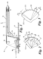
- a handbrake lever assembly 10 has a brake lever 11 pivotally connected to a mounting bracket 12 by means of a pivot pin 19.
- the mounting bracket 12 is attached to part of the body structure of a motor vehicle in this case a floor structure 8 by means of bolts 9.
- the brake lever 11 pivotally supports a pawl 14 for engagement with a ratchet 13 formed as part of the mounting bracket 12.
- the pawl 14 and the ratchet 13 form a retaining means which can be selectively used to hold the brake lever 11 in a number of positions.
- the ratchet 13 has a number of teeth which define distinct positions of the brake lever corresponding to different degrees of engagement of the parking brake. The teeth are evenly spaced giving the ratchet a constant pitch.
- the pawl 14 is moveable into and out of engagement with the ratchet member 13 by means of a rod 15 connected to a push button 16.
- the push button 16 is biased by a spring 17 so as to produce a pawl engaging force in the rod 15.
- the brake lever 11 can be moved in a brake applying direction by applying a force to it in the direction of arrow 'X'. This causes the brake lever 11 to be rotated relative to the mounting bracket 12. There is no need to apply a pressure to the push button 16 as the pawl 14 is shaped to move from one tooth of the ratchet means to the next in the brake force applying direction.
- a brake cable 18 is attached at one end to the brake lever 11 and is connected at its other end to a brake means (not shown) used to hold the motor vehicle in a stationary or parked position.
- a brake means (not shown) used to hold the motor vehicle in a stationary or parked position.
- the ratchet is arranged to hold the lever 11 in a plurality of positions in the third range at least, and generally over a broader range of positions to allow for adjustment of the brakes.
- a brake lever assembly according to a first embodiment of the invention is similar to that shown in Figure 1, except for the ratchet 113 which is shown in Figure 2.
- the pitch of the teeth 50 on the ratchet 113 is not uniform, there being three series of teeth 50, each series being of a uniform pitch but no series having the same pitch as the pitch of the other series.
- the first series 'A' of teeth 50 has a coarse pitch 'P1' so that a relatively large movement of the brake lever is required to move from one tooth 50 to the next.
- the second series 'B' of teeth 50 has a less coarse pitch 'P2' so that a smaller movement of the brake lever is required to move from one tooth 50 to the next compared to the series 'A'.
- the third series 'C' of teeth 50 has a fine pitch 'P3' so that a relatively small movement of the brake lever is required to move from one tooth 50 to the next.
- the pitch 'P1' is approximately twice that of the pitch 'P3'.
- a ratchet 113 forming part of a brake lever assembly according to a second embodiment of the invention includes teeth of a continuously varying pitch.
- the pitch 'P2' between the second and third teeth 60 is less than the pitch 'P1' between the first and second teeth 60 and this pattern is continued along the ratchet member 213 so that the pitch of the teeth 60 decreases along the ratchet member 213. This means that as the brake lever is moved from an unapplied position to an applied position the distance between the distinct positions of application reduces.
- the pitch 'P1' is approximately twice that of the pitch 'PN' between the last and the second to last teeth 60.
- the invention is not limited to an arrangement in which the push button is pressed to release the brake lever but could also be used for 'fly-off' handbrakes where the push button has to be pressed to engage the pawl member with the ratchet member.
Landscapes
- Engineering & Computer Science (AREA)
- Transportation (AREA)
- Mechanical Engineering (AREA)
- Braking Elements And Transmission Devices (AREA)
- Transmission Devices (AREA)
Applications Claiming Priority (2)
| Application Number | Priority Date | Filing Date | Title |
|---|---|---|---|
| GBGB9825082.2A GB9825082D0 (en) | 1998-11-17 | 1998-11-17 | A motor vehicle and a brake lever assembly therefor |
| GB9825082 | 1998-11-17 |
Publications (1)
| Publication Number | Publication Date |
|---|---|
| EP1002708A1 true EP1002708A1 (de) | 2000-05-24 |
Family
ID=10842521
Family Applications (1)
| Application Number | Title | Priority Date | Filing Date |
|---|---|---|---|
| EP99309023A Withdrawn EP1002708A1 (de) | 1998-11-17 | 1999-11-12 | Feststellbremsen für Kraftfahrzeuge |
Country Status (2)
| Country | Link |
|---|---|
| EP (1) | EP1002708A1 (de) |
| GB (2) | GB9825082D0 (de) |
Cited By (1)
| Publication number | Priority date | Publication date | Assignee | Title |
|---|---|---|---|---|
| WO2010013128A3 (en) * | 2008-08-01 | 2010-06-10 | Toyota Jidosha Kabushiki Kaisha | Lever device and parking brake apparatus |
Citations (2)
| Publication number | Priority date | Publication date | Assignee | Title |
|---|---|---|---|---|
| GB715787A (en) * | 1952-06-24 | 1954-09-22 | Ransomes & Rapier Ltd | Improvements in or relating to lever gear mechanism particularly for operating vehicle brakes |
| GB2301657A (en) * | 1995-06-02 | 1996-12-11 | Ford Motor Co | Handbrake lever |
Family Cites Families (1)
| Publication number | Priority date | Publication date | Assignee | Title |
|---|---|---|---|---|
| US5588335A (en) * | 1995-04-28 | 1996-12-31 | Strait; Daniel L. | Torsion lock parking brake actuator with push down release |
-
1998
- 1998-11-17 GB GBGB9825082.2A patent/GB9825082D0/en not_active Ceased
-
1999
- 1999-11-12 GB GB9926696A patent/GB2344871A/en not_active Withdrawn
- 1999-11-12 EP EP99309023A patent/EP1002708A1/de not_active Withdrawn
Patent Citations (2)
| Publication number | Priority date | Publication date | Assignee | Title |
|---|---|---|---|---|
| GB715787A (en) * | 1952-06-24 | 1954-09-22 | Ransomes & Rapier Ltd | Improvements in or relating to lever gear mechanism particularly for operating vehicle brakes |
| GB2301657A (en) * | 1995-06-02 | 1996-12-11 | Ford Motor Co | Handbrake lever |
Cited By (1)
| Publication number | Priority date | Publication date | Assignee | Title |
|---|---|---|---|---|
| WO2010013128A3 (en) * | 2008-08-01 | 2010-06-10 | Toyota Jidosha Kabushiki Kaisha | Lever device and parking brake apparatus |
Also Published As
| Publication number | Publication date |
|---|---|
| GB2344871A (en) | 2000-06-21 |
| GB9926696D0 (en) | 2000-01-12 |
| GB9825082D0 (en) | 1999-01-13 |
Similar Documents
| Publication | Publication Date | Title |
|---|---|---|
| US4872368A (en) | Push-to-release cable operating apparatus | |
| EP0527518B1 (de) | Selbstnachstellende, durch Niederdrücken zu lösende Parkbremse | |
| EP0928727A3 (de) | Fahrzeugbremspedalanordnung | |
| US7219576B2 (en) | Variable ratio pedal assembly | |
| US5775174A (en) | Vehicular foot-operated parking brake control apparatus | |
| EP0164231B1 (de) | Parkbremsmechanismus | |
| US4615235A (en) | Variable ratio brake pedal mechanism | |
| EP0050540A1 (de) | Aufbau einer Bremspedalverbindung | |
| EP1243456B1 (de) | Bremspedalvorrichtung | |
| US7448296B2 (en) | Brake pedal apparatus | |
| US3459065A (en) | Parking brake actuator and control mechanism | |
| EP1002708A1 (de) | Feststellbremsen für Kraftfahrzeuge | |
| EP1225363A2 (de) | Bremsmechanismus | |
| JP2006103501A (ja) | 車両用ペダルの後退防止装置 | |
| JP3942990B2 (ja) | 可動ペダル装置 | |
| US6079794A (en) | Brake-actuating device | |
| EP1839976A2 (de) | Bremspedal mit Veränderung des Hebelverhältnisses | |
| US3315538A (en) | Mechanism control | |
| KR100259244B1 (ko) | 풋 작동식 주차 브레이크 | |
| JPH05288266A (ja) | 車両のパーキングロック解除装置 | |
| KR200149985Y1 (ko) | 자동차용 풋 파킹 브레이크 | |
| KR100511857B1 (ko) | 자동차의 브레이크 페달 시스템 | |
| KR0174416B1 (ko) | 차량용 주차 브레이크 레버 | |
| JP3772387B2 (ja) | パーキングブレーキ装置 | |
| KR19980017365A (ko) | 주차용 풋 브레이크 |
Legal Events
| Date | Code | Title | Description |
|---|---|---|---|
| PUAI | Public reference made under article 153(3) epc to a published international application that has entered the european phase |
Free format text: ORIGINAL CODE: 0009012 |
|
| AK | Designated contracting states |
Kind code of ref document: A1 Designated state(s): AT BE CH CY DE DK ES FI FR GB GR IE IT LI LU MC NL PT SE |
|
| AX | Request for extension of the european patent |
Free format text: AL;LT;LV;MK;RO;SI |
|
| AKX | Designation fees paid | ||
| RAP1 | Party data changed (applicant data changed or rights of an application transferred) |
Owner name: BAYERISCHE MOTOREN WERKE AKTIENGESELLSCHAFT |
|
| STAA | Information on the status of an ep patent application or granted ep patent |
Free format text: STATUS: THE APPLICATION IS DEEMED TO BE WITHDRAWN |
|
| 18D | Application deemed to be withdrawn |
Effective date: 20001125 |
|
| REG | Reference to a national code |
Ref country code: DE Ref legal event code: 8566 |