EP1002755A2 - Dispositif pour séparer des cahiers de feullies d'une ligne de transport - Google Patents
Dispositif pour séparer des cahiers de feullies d'une ligne de transport Download PDFInfo
- Publication number
- EP1002755A2 EP1002755A2 EP99121101A EP99121101A EP1002755A2 EP 1002755 A2 EP1002755 A2 EP 1002755A2 EP 99121101 A EP99121101 A EP 99121101A EP 99121101 A EP99121101 A EP 99121101A EP 1002755 A2 EP1002755 A2 EP 1002755A2
- Authority
- EP
- European Patent Office
- Prior art keywords
- sheet layers
- conveyor
- conveyor belt
- line
- conveying direction
- Prior art date
- Legal status (The legal status is an assumption and is not a legal conclusion. Google has not performed a legal analysis and makes no representation as to the accuracy of the status listed.)
- Granted
Links
- 238000012546 transfer Methods 0.000 title claims description 36
- 238000006073 displacement reaction Methods 0.000 claims description 35
- 238000000034 method Methods 0.000 claims description 26
- 238000007599 discharging Methods 0.000 claims description 8
- 239000004033 plastic Substances 0.000 claims description 7
- 239000000123 paper Substances 0.000 description 42
- 238000012545 processing Methods 0.000 description 19
- 238000004806 packaging method and process Methods 0.000 description 8
- 230000008569 process Effects 0.000 description 6
- 238000004519 manufacturing process Methods 0.000 description 5
- 238000005516 engineering process Methods 0.000 description 4
- 230000007246 mechanism Effects 0.000 description 3
- 239000011111 cardboard Substances 0.000 description 2
- 238000005520 cutting process Methods 0.000 description 2
- 239000011888 foil Substances 0.000 description 2
- 230000007257 malfunction Effects 0.000 description 2
- 238000003860 storage Methods 0.000 description 2
- 239000000725 suspension Substances 0.000 description 2
- 230000001133 acceleration Effects 0.000 description 1
- 238000009825 accumulation Methods 0.000 description 1
- 230000009471 action Effects 0.000 description 1
- 230000008859 change Effects 0.000 description 1
- 238000010924 continuous production Methods 0.000 description 1
- 238000013461 design Methods 0.000 description 1
- 238000010586 diagram Methods 0.000 description 1
- 238000012423 maintenance Methods 0.000 description 1
- 239000002184 metal Substances 0.000 description 1
- 238000003825 pressing Methods 0.000 description 1
- 230000009467 reduction Effects 0.000 description 1
- 230000000284 resting effect Effects 0.000 description 1
- 238000013517 stratification Methods 0.000 description 1
- 230000001360 synchronised effect Effects 0.000 description 1
Images

Classifications
-
- B—PERFORMING OPERATIONS; TRANSPORTING
- B65—CONVEYING; PACKING; STORING; HANDLING THIN OR FILAMENTARY MATERIAL
- B65H—HANDLING THIN OR FILAMENTARY MATERIAL, e.g. SHEETS, WEBS, CABLES
- B65H31/00—Pile receivers
- B65H31/30—Arrangements for removing completed piles
- B65H31/3081—Arrangements for removing completed piles by acting on edge of the pile for moving it along a surface, e.g. by pushing
-
- B—PERFORMING OPERATIONS; TRANSPORTING
- B65—CONVEYING; PACKING; STORING; HANDLING THIN OR FILAMENTARY MATERIAL
- B65G—TRANSPORT OR STORAGE DEVICES, e.g. CONVEYORS FOR LOADING OR TIPPING, SHOP CONVEYOR SYSTEMS OR PNEUMATIC TUBE CONVEYORS
- B65G51/00—Conveying articles through pipes or tubes by fluid flow or pressure; Conveying articles over a flat surface, e.g. the base of a trough, by jets located in the surface
- B65G51/02—Directly conveying the articles, e.g. slips, sheets, stockings, containers or workpieces, by flowing gases
- B65G51/03—Directly conveying the articles, e.g. slips, sheets, stockings, containers or workpieces, by flowing gases over a flat surface or in troughs
-
- B—PERFORMING OPERATIONS; TRANSPORTING
- B65—CONVEYING; PACKING; STORING; HANDLING THIN OR FILAMENTARY MATERIAL
- B65H—HANDLING THIN OR FILAMENTARY MATERIAL, e.g. SHEETS, WEBS, CABLES
- B65H29/00—Delivering or advancing articles from machines; Advancing articles to or into piles
- B65H29/58—Article switches or diverters
-
- B—PERFORMING OPERATIONS; TRANSPORTING
- B65—CONVEYING; PACKING; STORING; HANDLING THIN OR FILAMENTARY MATERIAL
- B65H—HANDLING THIN OR FILAMENTARY MATERIAL, e.g. SHEETS, WEBS, CABLES
- B65H33/00—Forming counted batches in delivery pile or stream of articles
- B65H33/16—Forming counted batches in delivery pile or stream of articles by depositing articles in batches on moving supports
-
- B—PERFORMING OPERATIONS; TRANSPORTING
- B65—CONVEYING; PACKING; STORING; HANDLING THIN OR FILAMENTARY MATERIAL
- B65H—HANDLING THIN OR FILAMENTARY MATERIAL, e.g. SHEETS, WEBS, CABLES
- B65H2301/00—Handling processes for sheets or webs
- B65H2301/40—Type of handling process
- B65H2301/42—Piling, depiling, handling piles
- B65H2301/422—Handling piles, sets or stacks of articles
- B65H2301/4224—Gripping piles, sets or stacks of articles
-
- B—PERFORMING OPERATIONS; TRANSPORTING
- B65—CONVEYING; PACKING; STORING; HANDLING THIN OR FILAMENTARY MATERIAL
- B65H—HANDLING THIN OR FILAMENTARY MATERIAL, e.g. SHEETS, WEBS, CABLES
- B65H2301/00—Handling processes for sheets or webs
- B65H2301/40—Type of handling process
- B65H2301/42—Piling, depiling, handling piles
- B65H2301/422—Handling piles, sets or stacks of articles
- B65H2301/4226—Delivering, advancing piles
- B65H2301/42264—Delivering, advancing piles by moving the surface supporting the lowermost article of the pile, e.g. conveyor, carriage
-
- B—PERFORMING OPERATIONS; TRANSPORTING
- B65—CONVEYING; PACKING; STORING; HANDLING THIN OR FILAMENTARY MATERIAL
- B65H—HANDLING THIN OR FILAMENTARY MATERIAL, e.g. SHEETS, WEBS, CABLES
- B65H2301/00—Handling processes for sheets or webs
- B65H2301/40—Type of handling process
- B65H2301/42—Piling, depiling, handling piles
- B65H2301/422—Handling piles, sets or stacks of articles
- B65H2301/4226—Delivering, advancing piles
- B65H2301/42266—Delivering, advancing piles by acting on edge of the pile for moving it along a surface, e.g. pushing
-
- B—PERFORMING OPERATIONS; TRANSPORTING
- B65—CONVEYING; PACKING; STORING; HANDLING THIN OR FILAMENTARY MATERIAL
- B65H—HANDLING THIN OR FILAMENTARY MATERIAL, e.g. SHEETS, WEBS, CABLES
- B65H2404/00—Parts for transporting or guiding the handled material
- B65H2404/20—Belts
- B65H2404/23—Belts with auxiliary handling means
- B65H2404/232—Blade, plate, finger
- B65H2404/2321—Blade, plate, finger on two opposite belts or set of belts, i.e. having active handling section cooperating with and facing to each other
-
- B—PERFORMING OPERATIONS; TRANSPORTING
- B65—CONVEYING; PACKING; STORING; HANDLING THIN OR FILAMENTARY MATERIAL
- B65H—HANDLING THIN OR FILAMENTARY MATERIAL, e.g. SHEETS, WEBS, CABLES
- B65H2404/00—Parts for transporting or guiding the handled material
- B65H2404/70—Other elements in edge contact with handled material, e.g. registering, orientating, guiding devices
- B65H2404/73—Means for sliding the handled material on a surface, e.g. pushers
-
- B—PERFORMING OPERATIONS; TRANSPORTING
- B65—CONVEYING; PACKING; STORING; HANDLING THIN OR FILAMENTARY MATERIAL
- B65H—HANDLING THIN OR FILAMENTARY MATERIAL, e.g. SHEETS, WEBS, CABLES
- B65H2405/00—Parts for holding the handled material
- B65H2405/50—Gripping means
- B65H2405/52—Gripping means reciprocating
-
- B—PERFORMING OPERATIONS; TRANSPORTING
- B65—CONVEYING; PACKING; STORING; HANDLING THIN OR FILAMENTARY MATERIAL
- B65H—HANDLING THIN OR FILAMENTARY MATERIAL, e.g. SHEETS, WEBS, CABLES
- B65H2406/00—Means using fluid
- B65H2406/10—Means using fluid made only for exhausting gaseous medium
- B65H2406/11—Means using fluid made only for exhausting gaseous medium producing fluidised bed
-
- B—PERFORMING OPERATIONS; TRANSPORTING
- B65—CONVEYING; PACKING; STORING; HANDLING THIN OR FILAMENTARY MATERIAL
- B65H—HANDLING THIN OR FILAMENTARY MATERIAL, e.g. SHEETS, WEBS, CABLES
- B65H2701/00—Handled material; Storage means
- B65H2701/10—Handled articles or webs
- B65H2701/17—Nature of material
- B65H2701/176—Cardboard
Definitions
- the invention relates to a device for discharging sheet layers, in particular of paper giants, from a first conveyor line, with a first conveyor belt with a first conveying direction for transporting the sheet layers on the first Conveyor line, with a transfer device for transferring the sheet layers from the first conveyor line, with a receiving device for receiving the from the first conveyor line offset sheet layers.
- Such devices are known from the prior art. These devices are state of the art in the paper processing industry used.
- One branch of this paper processing industry is manufacturing so-called giant.
- These giants are leaf layers made of leaves made of paper, cardboard, foil, plastic and the like, which in large numbers, i.e. e.g. in a number of 500 sheets or more, stacked one on top of the other in sheet layers are.
- too Cutting machines or Sheeter called, from bobbins of the corresponding Stripped sheets of paper, cardboard, foil, plastic or the like. in single sheets cut and then cut these single sheets into layers or Stacking preferably constant number of sheets, i.e. the actual sheet positions or Giants accumulated.
- Cutting machines are used in the prior art usually several layers of leaves arranged side by side in a row made available.
- the individual giant or giant rows are then the desired ones Processing equipment supplied. This is usually done with conveyor belts. Such as an intermediate link between the sheeter and the processing Machine-operated conveyor belts have to perform a wide variety of tasks fulfill.
- One of these tasks is that existing ones exist in the prior art Sheeter have now reached very high output frequencies. Should now corresponding output to giants, for example from a packaging machine to Packaging of the giant manufactured by the Sheeter are processed further, so this causes problems due to the high output frequency of the sheeter. Because the Packaging machines on the market today can handle the high Ejection frequencies of the sheeter do not continue at the same speed to process.
- the giant or giant rows produced by the Sheeter must therefore divided into two or more packaging machines in the prior art become.
- the present invention therefore deals generically with sheet layers, in particular to discharge giant or giant rows from a conveyor line or from to transfer one conveyor line to another.
- a known device for transferring sheet layers from a conveyor line another shows, for example, DE 44 15 047 A1.
- This publication describes like a malfunction on a conveyor line to remove the Sheet layers from the sheeter the sheet layers to a second parallel to the first Conveyor line running conveyor line can be spent.
- the aforementioned publication discloses two conveyor belts, the accumulation or acceleration sections to the rows originating from the sheeter to bring the sheet layers into a distance from each other.
- the publication also shows third conveyor belts running diagonally to the aforementioned conveyor belts, the sheet layers of the one in the event of a fault in a further processing machine on this disturbed machine running conveyor belt on the other, on the Conveyor belt running undisturbed with the help of the diagonal conveyor belts can spend.
- a disadvantage of this prior art is that the conveyor belt the other conveyor belt to be moved giant through the diagonal conveyor belts or through the diagonal movement and the associated change of direction Exposed to forces that the perfect stack of the individual leaves in the respective ream.
- This represents one serious disadvantage because due to the already mentioned several times high Speed of the sheeter a slipped stack of paper the production plant would slow down significantly.
- such an asymmetrical ream can be also no longer process or only with very considerable loss of quality.
- DE-OS 27 08 131 Another prior art is known from DE-OS 27 08 131. At that one shown device for transferring stacks of paper sheets from a production facility on two packaging facilities are diagonal between the Conveyor tracks running rails provided. Run on these rails again pallets that carry the actual sheet layers. The transportation of the The sheet layers arranged on the pallets are controlled by appropriate switches.
- the invention relates to an air table for holding objects, with a plurality of openings in one of the object to be picked up facing surface of the air table, from which air forms an air cushion between the surface and the bottom of the one on the air table Object can leak, with ball valves in the openings that the Airflow when placing the object to be picked up on the surface of the air table.
- Such an air table is known for example from DE 24 49 620 C2.
- This Document shows an air table by elongated in the aforementioned openings Closure members are arranged.
- the invention relates to a method for discharging sheet layers a first conveyor line, with the steps: the sheet layers are on the first Conveyor line transported by a first conveyor belt in a first conveying direction, the transport of the sheet layers in the first conveying direction is interrupted, in order to be able to discharge the leaf layers.
- the object of the present invention is therefore in a device of the beginning to avoid the disadvantages mentioned above, and a faster and enable smoother transport or further processing of sheet layers.
- Another object of the present invention is to provide the air table to avoid the aforementioned disadvantages and an air table to provide the aforementioned type, in which already with a small Air pressure in the air table moving the objects on it is possible.
- Another object of the present invention is to provide a method which occurs in connection with the previously described method Avoids disadvantages, and makes it possible with as few procedural steps as possible a discharge of a sheet layer or the transfer of a sheet layer from a first conveyor line to a second conveyor line, and in doing so to ensure a minimal obstruction of the funding lines.
- the first task in a device of the type mentioned above solved that the displacement device on the side facing away from the conveyor belt Sheet layers, spaced from the sheet layers, and that the displacement device the sheet layers when moving them from that of the conveyor belt grips the opposite side of the sheet layers starting from the side.
- the second task is for an air table of the type mentioned above solved that the ball valves consist of balls made of plastic.
- the third object is achieved in that the method Has steps: the sheet layers are from above by a transfer device The sheet layers are taken by the transfer device from the conveyor line spent, the transport of the sheet layers on the first conveyor line immediately after the transfer device has left the conveyor line, continued.
- the first line of funding lies in particular in the fact that, due to the fact that the Sheet layers acting displacement device, the displacement device spaced is arranged to the top of the sheet layers, and wherein the displacement device grabs the sheet layers to move them from the side that Disadvantages known from the prior art can be avoided.
- the transfer device does not protrude across the conveying path of the Paper giant over, so that in the invention, the conveyor line the next stack of paper immediately after leaving the stack of paper to be discharged at the Can promote transfer position without being on the one that is being removed Having to wait for the stack of paper still moving.
- the present Invention In the state of the Technology is therefore the first conveyor belt blocked until the transfer device has returned to its original position.
- the present Invention is the blockage of the first conveyor belt compared to the state of technology is reduced to a considerable extent to the short period in which the Transfer device displaces the ream to be discharged from the first conveyor belt.
- the first conveyor belt can continue operate.
- the present invention therefore results in a complete Significant speed increase in the paper processing industry necessary conveyor belts, working on Sheeter also cross conveyor called.
- a preferred embodiment of the invention is characterized in that the Moving device for moving the sheet layers into engagement with the sheet layers can be brought slide, which on the sheet layers on their parallel to the conveying direction comprehends sides of the conveyor belt. It is particularly preferred that the slide grips the sheet layers to be moved from both sides. This gripping can take place, for example, in that the slider one forms a box open at the bottom, over the sheet layer to be moved from above is slipped here. Here is the opening facing the sheet layer to be moved the box adapted to the size of the sheet layer to be moved. Once the box is completely slipped over the sheet layer to be moved, which can preferably cross offset movement running to the first conveying direction are carried out.
- the box is only parallel to the conveying direction extending side walls, while the perpendicular to the first conveying direction extending side walls are omitted. It is particularly advantageous that none on the expansion of the sheet layers in the direction of the first conveying direction Must be taken into account. The box therefore only needs to extend the Sheet positions perpendicular to the first conveying direction are adjusted. In this regard, you can For example, correspondingly adjustable side walls of the box are provided his.
- the side walls are the box is designed pivotable as swivel flaps.
- the box is designed pivotable as swivel flaps.
- the swivel flaps of the slide can be folded down to grasp a sheet layer to be moved.
- the swivel flaps can go up again be folded so that the slide thus formed back again over the first conveyor belt can be moved without the work of the first conveyor belt to hinder.
- the swivel axis preferably parallel to the conveying direction of the The first conveyor belt runs into its engagement position parallel to the direction of conveyance running sides of the sheet or sheets to be discharged, so to engage the corresponding sides of the sheet layers.
- a particularly advantageous embodiment is distinguished the invention characterized in that simultaneously with the swiveling up Swing flaps to the side of the sheet to be moved or to be moved Sheet layers from above the sheet layers exert a force towards the first conveyor belt is exercised.
- This force can, for example, be applied from above offsetting sheet layer weight applied.
- This touchdown the weight is preferably synchronized with the pivoting the swing flaps.
- This embodiment therefore becomes the one to be moved Sheet stack fixed both in the direction of offset and from above.
- This Embodiment is therefore an optimal maintenance of the exact stratification of the individual sheets of the sheet layers or the giant during the transfer possible. After completing the displacement movement, this is then from above onto the sheet layer pressing weight lifted off again. This also happens preferably at the same time or synchronously with the pivoting away to move the sheet position serving swing flaps of the slide.
- An embodiment is particularly preferred in which the swivel flaps in the Rest position of the slide in a substantially horizontal plane are folded up while the swivel flaps act on the side leaf layers to be displaced by approximately 90 ° downwards in the direction of the first Conveyor belt can be pivoted sideways to the sheet to be moved. Offer by the horizontal arrangement of the swivel flaps in their rest position the swivel flaps have the lowest possible air resistance. This reduces the Turbulence when retracting the slide with the swivel flaps in the position above the first conveyor.
- the air swirl is still thereby reduced that the swivel flap of the serving as a displacement device Slider are provided with a variety of holes through the air when Moving the sheet layers can pass through.
- Another preferred embodiment of the invention is characterized in that that the first conveyor belt runs in a table, preferably in an air table.
- the width of the conveyor belt can also be narrower transversely to the conveying direction be selected as the sheet layers to be conveyed. Because with the one embedded in the table The conveyor belt can then slide the sheet sheet being conveyed on the table.
- the conveyor belt lowers in synchronism with that Relocate the leaf layers. In this way, the conveyor belt does not interfere with the displacement movement the sheet position by the transfer device.
- the second Has conveyor line in which a second conveyor belt with a parallel to the first Direction of conveying extending second conveying direction is provided.
- This embodiment is characterized in that with the help of the transfer device Sheet layers can be moved from one of the conveyor belts to the other conveyor belt are.
- This embodiment of the invention can therefore be used to convert the paper giant delivered by a Sheeter to two Distributing packaging machines running conveyor belts. Just like the Removal of sheet layers or paper giants described above can also in this embodiment, whole rows of paper giants at the same time using the Moving device on a conveyor belt, which laterally engages these rows to be transferred to the other.
- the aforementioned embodiment therefore advantageously overcomes the im Disadvantages known from the prior art when moving giant rows or individual giants from one conveyor belt to another. Because the displacement device according to the invention only hinders the first conveyor belt as long as it is to be moved Giant row removed from the first conveyor belt. As soon as the transfer device with of the ream row to be moved has left the first conveyor belt, the first Conveyor belt continue to work without hindrance while the Ries series from the Moving device is still placed on the second conveyor belt. The return movement too the transfer device into its position above the first conveyor belt According to the invention, this does not hinder the operation of the first conveyor belt.
- both conveyor belts are embedded in an air table, which is also the two conveyor belts connects with each other.
- the sheet layers to be moved or the giant or giant rows to be moved are gripped on the first conveyor belt then with the help of the transfer device over the between the Conveyor belts provided are pushed and then on the second conveyor belt - still resting on the air table - again to be set down from the second conveyor belt to a further processing machine to be promoted further.
- the air table is the one according to the invention Air table with balls made of plastic, because the inventive Balls, which are preferably made of light plastic, lower that for the Air table requires air pressure because plastic balls are lighter than metal balls are and therefore little force to close the air outlet openings due to the air pressure of the air table.
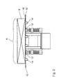
- FIG. 1 shows a device according to the invention for transferring rows of rivers 2 (see Figure 3) from a first conveyor line 4 to a parallel to the first Funding line 4 running second funding line 6.
- the from the first funding line 4th discharge rows 2 to be discharged and moved to the second conveyor line 6 consist of several giants 8.
- the first conveyor line 4 consists of two first, which are embedded in an air table 10 Conveyor belts 12.
- the conveyor belts 12 run parallel to a conveying direction 20 of the conveyor line 4.
- the air table 10 has openings 14 into the ball valves 16 are incorporated.
- An air pressure not shown, can be built up in the air table 10, which from below against the ball valves 16 of the openings 14 of the air table 10 presses.
- the ball valves 16 are therefore over the surface 18 of the air table 10 pressed out of the air table 10. This state is, for example shown in the middle of Figure 1.
- the aforementioned sliding of the object or the giant 8 shown occurs even if the giant 8 are conveyed on the conveyor lines 4 and 6 respectively.
- the conveying direction 20 in FIG. 1 runs perpendicular to the paper plane. It can with a switch, not shown, the conveying direction 20 changed by 180 ° are, as indicated by the arrows 20 in Figure 3.
- the first conveyor belts are located 12 in a lowered state in the air table 10. So that stores individual ream 8 and thus the ream row 2 no longer on the conveyor belts 12, but on the air cushion, not shown, between the surface 18 of the Air table 10 and the bottom of the giant 8.
- a displacement device 24 is shown above the conveyor line 4.
- the transfer device 24 is the core of the invention, also referred to as "transposer" Device 1.
- the transfer device 24 consists essentially a slide 26 and a guide 28 for the slide 26.
- the slide 26 is arranged at a distance from the air table 10.
- the slide 26 has one Base plate 30 on.
- the base plate 30 is on a suspension 32 on the guide 28 of the transfer device 24 suspended. With the help of a drive 34 can the suspension 32 and thus the displacement device 24 along the guide 28 parallel to the plane of the air table 10 and transversely to the conveying direction 20 between move the first conveyor line 4 and the second conveyor line 6.
- the slide 26 has two swivel plates 36.
- the swivel plates are in FIG. 1 in the above the first conveyor line 4 shown position in its engagement position with the leaf web 8 to be moved shown.
- the swivel plates 36 are in this engagement position perpendicular to the surface 18 of the air table 10. To get into this position are the swivel plates 36 with the help of a only shown schematically Swivel plate drive 38 around its parallel to the conveying direction of the first conveyor line 4 extending swivel axes 40 laterally to the row of reams 2 with the giant 8 been swung up.
- the transfer device shows that the width of the individual giant can be adjusted an adjustment mechanism 46 above the base plate 30.
- this adjustment mechanism 46 With the help of this adjustment mechanism 46, the swivel axes 40 of the swivel plates 36 of the slide 26 can be moved perpendicular to the conveying direction and thus be adapted to the corresponding ream width.
- the displacement device 24 moves back in the position shown on the left in FIG. 1. There begins for the shift a further row of reams 2 the procedure of swinging up already described above the swivel plates 36 about the swivel axes 40 to the one to be displaced Ream row 2. During the backward movement of the transfer device 24 normal operation is possible on both conveyor lines 4 and 6.
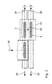
- FIG. 2 shows the detail shown on the left in FIG. 1 in an enlargement.
- the displacement device 24 was omitted.
- FIG. 3 shows the principle of shifting the rows of rivers 2 between the individual conveyor lines 4 and 6.
- the figure shows 3 by means of arrows 20 that the conveying directions of the conveying lines 4 and 6, i.e. the working directions of the conveyor belts 12 and 22 are each rotated by 180 ° can be.
- the device according to the invention for transferring rows of rivers 2 from a first conveyor line 4 to a second one running parallel to this Line 6 can therefore be individually adapted to the circumstances. So can which adjoin the conveyor lines 4 and 6 on the right and left in FIG Processing machines (not shown) with the aid of the displacement device 24 individually to the performance represented by the symbolic arrow 56 of a sheeter, not shown, can be adapted.
Landscapes
- Engineering & Computer Science (AREA)
- Mechanical Engineering (AREA)
- Physics & Mathematics (AREA)
- Fluid Mechanics (AREA)
- Delivering By Means Of Belts And Rollers (AREA)
- Sheets, Magazines, And Separation Thereof (AREA)
- Separation, Sorting, Adjustment, Or Bending Of Sheets To Be Conveyed (AREA)
- Special Conveying (AREA)
- Primary Cells (AREA)
- Battery Mounting, Suspending (AREA)
- Processing And Handling Of Plastics And Other Materials For Molding In General (AREA)
- Specific Conveyance Elements (AREA)
- Structure Of Belt Conveyors (AREA)
- Apparatuses For Bulk Treatment Of Fruits And Vegetables And Apparatuses For Preparing Feeds (AREA)
- Branching, Merging, And Special Transfer Between Conveyors (AREA)
Applications Claiming Priority (2)
| Application Number | Priority Date | Filing Date | Title |
|---|---|---|---|
| DE19851780A DE19851780A1 (de) | 1998-11-10 | 1998-11-10 | Vorrichtung zum Ausschleusen von Blattlagen aus einer Förderlinie |
| DE19851780 | 1998-11-10 |
Publications (3)
| Publication Number | Publication Date |
|---|---|
| EP1002755A2 true EP1002755A2 (fr) | 2000-05-24 |
| EP1002755A3 EP1002755A3 (fr) | 2001-08-29 |
| EP1002755B1 EP1002755B1 (fr) | 2004-04-14 |
Family
ID=7887292
Family Applications (1)
| Application Number | Title | Priority Date | Filing Date |
|---|---|---|---|
| EP99121101A Expired - Lifetime EP1002755B1 (fr) | 1998-11-10 | 1999-10-22 | Dispositif pour séparer des cahiers de feullies d'une ligne de transport |
Country Status (7)
| Country | Link |
|---|---|
| US (1) | US20020060128A1 (fr) |
| EP (1) | EP1002755B1 (fr) |
| JP (1) | JP2000142972A (fr) |
| AT (1) | ATE264259T1 (fr) |
| DE (2) | DE19851780A1 (fr) |
| ES (1) | ES2216408T3 (fr) |
| PT (1) | PT1002755E (fr) |
Cited By (1)
| Publication number | Priority date | Publication date | Assignee | Title |
|---|---|---|---|---|
| WO2006130214A1 (fr) * | 2005-05-31 | 2006-12-07 | Kimberly-Clark Worldwide, Inc. | Appareil de transport aerien |
Families Citing this family (5)
| Publication number | Priority date | Publication date | Assignee | Title |
|---|---|---|---|---|
| JP3570366B2 (ja) * | 2000-09-13 | 2004-09-29 | 日本電気株式会社 | アービタ回路及びそれに用いる出力セルのアービトレーション方法 |
| DE102005046248A1 (de) * | 2005-09-27 | 2007-03-29 | Dürr Dental GmbH & Co. KG | Vorrichtung zum Auslesen von insbesondere flexiblen Speicherfolien |
| CN105480689A (zh) * | 2015-12-31 | 2016-04-13 | 宁波中亿自动化装备有限公司 | 一种同步器理料机 |
| CN112850108B (zh) * | 2021-01-28 | 2021-10-26 | 广州擎天德胜智能装备有限公司 | 一种倍速推入机、空调外机柔性生产线及其生产方法 |
| EP4650310A1 (fr) * | 2024-05-17 | 2025-11-19 | Yaskawa Nordic AB | Dispositif pour manipuler des piles de feuilles |
Citations (7)
| Publication number | Priority date | Publication date | Assignee | Title |
|---|---|---|---|---|
| US3822777A (en) | 1971-06-02 | 1974-07-09 | Maskinfab As K | Junction switch for conveying systems |
| DE2708131A1 (de) | 1977-02-25 | 1978-08-31 | Will E C H Gmbh & Co | Verfahren und vorrichtung zum ueberfuehren von papierbogenstapeln von einer produktionseinrichtung auf zwei verpackungseinrichtungen |
| DE3122632A1 (de) | 1981-06-06 | 1982-12-23 | Licentia Patent-Verwaltungs-Gmbh, 6000 Frankfurt | Anordnung zum verschieben eines gegenstandes auf einer auflageflaeche |
| DE2449620C2 (de) | 1974-10-18 | 1983-02-10 | C.F. Scheer & Cie Gmbh & Co, 7000 Stuttgart | Lufttisch zum leichtbeweglichen Handhaben von plattenförmigen Werkstücken, Papierstapeln u.dgl. |
| DE3403215A1 (de) | 1983-02-12 | 1984-08-16 | E.C.H. Will (Gmbh & Co), 2000 Hamburg | Einrichtung zum ausschleusen von papierstapeln aus einer foerderlinie |
| DE4415047A1 (de) | 1994-04-29 | 1995-11-02 | Will E C H Gmbh & Co | Verfahren und Vorrichtung zum Fördern von Blattlagen aus einer Sammelstation |
| DE4421325A1 (de) | 1994-06-17 | 1995-12-21 | Womako Masch Konstr | Verfahren und Vorrichtung zum Koordinieren der Leistung von Papierverarbeitungseinrichtungen |
Family Cites Families (11)
| Publication number | Priority date | Publication date | Assignee | Title |
|---|---|---|---|---|
| FR2339446A1 (fr) * | 1976-01-28 | 1977-08-26 | Servimetal | Procede de filage a tres grande vitesse de metaux et alliages legers |
| GB2134891B (en) * | 1983-02-12 | 1987-02-11 | Will E C H | Apparatus for manipulating stacks of paper sheets or the like |
| DE3448456C2 (de) * | 1983-05-17 | 1996-10-24 | Grapha Holding Ag | Vorrichtung zum Überführen einer aus einem Schuppenstrom abgetrennten Teilschuppe an eine Verarbeitungsstation |
| US4589812A (en) * | 1983-10-18 | 1986-05-20 | Pemco, Inc. | Method of and apparatus for stacking reams of paper sheets |
| GB8616897D0 (en) * | 1986-07-11 | 1986-08-20 | Systems Ltd | Air cushion device |
| DE3803578A1 (de) * | 1988-02-06 | 1989-08-17 | Minda Industrieanlagen Gmbh | Verfahren fuer die beschickung von stanzen, inline-maschinen o. dgl. mit aus wellpappebogen bestehenden paketen |
| JPH02233416A (ja) * | 1989-02-20 | 1990-09-17 | Sig (Schweiz Ind Ges) | 物品の分配装置 |
| DE4116969A1 (de) * | 1991-05-24 | 1992-11-26 | Will E C H Gmbh & Co | Vorrichtung zum foerdern von papierbogenstapeln |
| US5483856A (en) * | 1992-05-05 | 1996-01-16 | Marquip, Inc. | Apparatus and method for slitting corrugated paperboard boxes |
| DE19731656C1 (de) * | 1997-07-23 | 1999-01-28 | Centro Kontrollsysteme | Vorrichtung zum Überschieben von Verpackungseinheiten, insbesondere Kästen und Kartons zu Verteil- oder Aussortierzwecken |
| DE19743423A1 (de) * | 1997-10-01 | 1999-04-08 | Will E C H Gmbh & Co | Vorrichtung zum Überführen von Papierstapeln von einer ersten Förderbahn auf eine zweite Förderbahn |
-
1998
- 1998-11-10 DE DE19851780A patent/DE19851780A1/de not_active Ceased
-
1999
- 1999-10-22 AT AT99121101T patent/ATE264259T1/de active
- 1999-10-22 ES ES99121101T patent/ES2216408T3/es not_active Expired - Lifetime
- 1999-10-22 DE DE59909163T patent/DE59909163D1/de not_active Expired - Lifetime
- 1999-10-22 PT PT99121101T patent/PT1002755E/pt unknown
- 1999-10-22 EP EP99121101A patent/EP1002755B1/fr not_active Expired - Lifetime
- 1999-11-10 US US09/437,210 patent/US20020060128A1/en not_active Abandoned
- 1999-11-10 JP JP11319510A patent/JP2000142972A/ja active Pending
Patent Citations (7)
| Publication number | Priority date | Publication date | Assignee | Title |
|---|---|---|---|---|
| US3822777A (en) | 1971-06-02 | 1974-07-09 | Maskinfab As K | Junction switch for conveying systems |
| DE2449620C2 (de) | 1974-10-18 | 1983-02-10 | C.F. Scheer & Cie Gmbh & Co, 7000 Stuttgart | Lufttisch zum leichtbeweglichen Handhaben von plattenförmigen Werkstücken, Papierstapeln u.dgl. |
| DE2708131A1 (de) | 1977-02-25 | 1978-08-31 | Will E C H Gmbh & Co | Verfahren und vorrichtung zum ueberfuehren von papierbogenstapeln von einer produktionseinrichtung auf zwei verpackungseinrichtungen |
| DE3122632A1 (de) | 1981-06-06 | 1982-12-23 | Licentia Patent-Verwaltungs-Gmbh, 6000 Frankfurt | Anordnung zum verschieben eines gegenstandes auf einer auflageflaeche |
| DE3403215A1 (de) | 1983-02-12 | 1984-08-16 | E.C.H. Will (Gmbh & Co), 2000 Hamburg | Einrichtung zum ausschleusen von papierstapeln aus einer foerderlinie |
| DE4415047A1 (de) | 1994-04-29 | 1995-11-02 | Will E C H Gmbh & Co | Verfahren und Vorrichtung zum Fördern von Blattlagen aus einer Sammelstation |
| DE4421325A1 (de) | 1994-06-17 | 1995-12-21 | Womako Masch Konstr | Verfahren und Vorrichtung zum Koordinieren der Leistung von Papierverarbeitungseinrichtungen |
Cited By (1)
| Publication number | Priority date | Publication date | Assignee | Title |
|---|---|---|---|---|
| WO2006130214A1 (fr) * | 2005-05-31 | 2006-12-07 | Kimberly-Clark Worldwide, Inc. | Appareil de transport aerien |
Also Published As
| Publication number | Publication date |
|---|---|
| EP1002755A3 (fr) | 2001-08-29 |
| US20020060128A1 (en) | 2002-05-23 |
| ATE264259T1 (de) | 2004-04-15 |
| EP1002755B1 (fr) | 2004-04-14 |
| DE59909163D1 (de) | 2004-05-19 |
| ES2216408T3 (es) | 2004-10-16 |
| JP2000142972A (ja) | 2000-05-23 |
| PT1002755E (pt) | 2004-08-31 |
| DE19851780A1 (de) | 2000-05-11 |
Similar Documents
| Publication | Publication Date | Title |
|---|---|---|
| DE2534819C2 (de) | Vorrichtung zum Entstapeln und Transportieren von Platinen | |
| DE69500305T2 (de) | Stapel-, Trennungs- und Abführungsstation für blattförmiges Gut, das von einer Verarbeitungsmaschine abgegeben wird | |
| DE69702274T2 (de) | Vorrichtung zum Sammeln und Stapeln von Schichtwerkstoffen, und ein Stapelverfahren | |
| EP1348651B1 (fr) | Dispositif de transport et procédé pour transférer des piles de papier ou similaire sur un conveyeur d'évacuation | |
| DE4224010A1 (de) | Vorrichtung zum handhaben von bahn- oder bogenmaterial aus papier | |
| EP0392139A2 (fr) | Dispositif pour déposer des liasses de feuilles, en particulier des feuilles en papier, sur une pile | |
| DE19833851A1 (de) | Verfahren und Vorrichtung zur Erstellung eines gedrehten Produktstromes mit einem Eckengreifer | |
| EP1002755B1 (fr) | Dispositif pour séparer des cahiers de feullies d'une ligne de transport | |
| EP3148789B1 (fr) | Dispositif et procédé pour transporter descorps de sacs tubulaires | |
| EP0958219A1 (fr) | Dispositif changeur de piles | |
| EP0465916B1 (fr) | Dispositif de convoyage pour unités en couches | |
| EP2062838A1 (fr) | Méthode et dispositif destinés au retrait de feuilles intermédiaires entre produits palettisés | |
| EP0896945B1 (fr) | Dispositif et procédé pour l'empilement des couches de piles en papier | |
| DE10141964B4 (de) | Verfahren und Vorrichtung zum Stapeln von Riesen | |
| EP1262435A1 (fr) | Méthode et dispositif pour empiler des matières premières, en particulier des feuilles de papier ou des groupes de feuilles de papier | |
| DE102012020943A1 (de) | Vorrichtung und Verfahren zum Falten und Zusammenlegen eines faltbaren Bahnelementes | |
| EP1784351B1 (fr) | Convoyeur et procede pour transferer des couches de feuilles sur un convoyeur de transport | |
| EP1868931B1 (fr) | Dispositif de regroupement | |
| EP2323938B1 (fr) | Dispositif de collecte et de transport d'empilements formés de couches de feuilles | |
| DE2520388A1 (de) | Kuehlbett fuer eine walzwerkanlage | |
| EP4086012A1 (fr) | Procédé et dispositif de tri de lamelles | |
| EP1274641B1 (fr) | Procede et dispositif pour former des groupes de feuilles comprenant une ou plusieurs feuilles | |
| DE3904720A1 (de) | Verfahren zum zufuehren eines geschlossenen blattstapels | |
| DE102018008014A1 (de) | Vorrichtung und Verfahren zum Transport von Werkstoffplatten | |
| DE102005045864A1 (de) | Verpackungsanlage und Verpackungsverfahren |
Legal Events
| Date | Code | Title | Description |
|---|---|---|---|
| PUAI | Public reference made under article 153(3) epc to a published international application that has entered the european phase |
Free format text: ORIGINAL CODE: 0009012 |
|
| AK | Designated contracting states |
Kind code of ref document: A2 Designated state(s): AT BE CH CY DE DK ES FI FR GB GR IE IT LI LU MC NL PT SE |
|
| AX | Request for extension of the european patent |
Free format text: AL;LT;LV;MK;RO;SI |
|
| RTI1 | Title (correction) |
Free format text: DEVICE FOR SEPARATING SHEET PILES FROM A TRANSFER LINE |
|
| RIC1 | Information provided on ipc code assigned before grant |
Free format text: 7B 65H 29/58 A, 7B 65H 33/16 B, 7B 65G 47/82 B |
|
| PUAL | Search report despatched |
Free format text: ORIGINAL CODE: 0009013 |
|
| RIC1 | Information provided on ipc code assigned before grant |
Free format text: 7B 65H 29/58 A, 7B 65H 33/16 B, 7B 65G 47/82 B, 7B 65G 51/03 B, 7B 65H 31/30 B |
|
| AK | Designated contracting states |
Kind code of ref document: A3 Designated state(s): AT BE CH CY DE DK ES FI FR GB GR IE IT LI LU MC NL PT SE |
|
| AX | Request for extension of the european patent |
Free format text: AL;LT;LV;MK;RO;SI |
|
| 17P | Request for examination filed |
Effective date: 20020228 |
|
| AKX | Designation fees paid |
Free format text: AT BE CH CY DE DK ES FI FR GB GR IE IT LI LU MC NL PT SE |
|
| 17Q | First examination report despatched |
Effective date: 20030218 |
|
| GRAP | Despatch of communication of intention to grant a patent |
Free format text: ORIGINAL CODE: EPIDOSNIGR1 |
|
| GRAS | Grant fee paid |
Free format text: ORIGINAL CODE: EPIDOSNIGR3 |
|
| GRAA | (expected) grant |
Free format text: ORIGINAL CODE: 0009210 |
|
| AK | Designated contracting states |
Kind code of ref document: B1 Designated state(s): AT BE CH CY DE DK ES FI FR GB GR IE IT LI LU MC NL PT SE |
|
| PG25 | Lapsed in a contracting state [announced via postgrant information from national office to epo] |
Ref country code: NL Free format text: LAPSE BECAUSE OF FAILURE TO SUBMIT A TRANSLATION OF THE DESCRIPTION OR TO PAY THE FEE WITHIN THE PRESCRIBED TIME-LIMIT Effective date: 20040414 Ref country code: IE Free format text: LAPSE BECAUSE OF FAILURE TO SUBMIT A TRANSLATION OF THE DESCRIPTION OR TO PAY THE FEE WITHIN THE PRESCRIBED TIME-LIMIT Effective date: 20040414 Ref country code: CY Free format text: LAPSE BECAUSE OF FAILURE TO SUBMIT A TRANSLATION OF THE DESCRIPTION OR TO PAY THE FEE WITHIN THE PRESCRIBED TIME-LIMIT Effective date: 20040414 |
|
| REG | Reference to a national code |
Ref country code: GB Ref legal event code: FG4D Free format text: NOT ENGLISH |
|
| REG | Reference to a national code |
Ref country code: CH Ref legal event code: EP |
|
| GBT | Gb: translation of ep patent filed (gb section 77(6)(a)/1977) |
Effective date: 20040414 |
|
| REF | Corresponds to: |
Ref document number: 59909163 Country of ref document: DE Date of ref document: 20040519 Kind code of ref document: P |
|
| REG | Reference to a national code |
Ref country code: IE Ref legal event code: FG4D Free format text: GERMAN |
|
| PG25 | Lapsed in a contracting state [announced via postgrant information from national office to epo] |
Ref country code: SE Free format text: LAPSE BECAUSE OF FAILURE TO SUBMIT A TRANSLATION OF THE DESCRIPTION OR TO PAY THE FEE WITHIN THE PRESCRIBED TIME-LIMIT Effective date: 20040714 Ref country code: GR Free format text: LAPSE BECAUSE OF FAILURE TO SUBMIT A TRANSLATION OF THE DESCRIPTION OR TO PAY THE FEE WITHIN THE PRESCRIBED TIME-LIMIT Effective date: 20040714 Ref country code: DK Free format text: LAPSE BECAUSE OF FAILURE TO SUBMIT A TRANSLATION OF THE DESCRIPTION OR TO PAY THE FEE WITHIN THE PRESCRIBED TIME-LIMIT Effective date: 20040714 |
|
| REG | Reference to a national code |
Ref country code: PT Ref legal event code: SC4A Free format text: AVAILABILITY OF NATIONAL TRANSLATION Effective date: 20040706 |
|
| NLV1 | Nl: lapsed or annulled due to failure to fulfill the requirements of art. 29p and 29m of the patents act | ||
| REG | Reference to a national code |
Ref country code: ES Ref legal event code: FG2A Ref document number: 2216408 Country of ref document: ES Kind code of ref document: T3 |
|
| PG25 | Lapsed in a contracting state [announced via postgrant information from national office to epo] |
Ref country code: LU Free format text: LAPSE BECAUSE OF NON-PAYMENT OF DUE FEES Effective date: 20041022 |
|
| PG25 | Lapsed in a contracting state [announced via postgrant information from national office to epo] |
Ref country code: MC Free format text: LAPSE BECAUSE OF NON-PAYMENT OF DUE FEES Effective date: 20041031 Ref country code: LI Free format text: LAPSE BECAUSE OF NON-PAYMENT OF DUE FEES Effective date: 20041031 Ref country code: CH Free format text: LAPSE BECAUSE OF NON-PAYMENT OF DUE FEES Effective date: 20041031 Ref country code: BE Free format text: LAPSE BECAUSE OF NON-PAYMENT OF DUE FEES Effective date: 20041031 |
|
| REG | Reference to a national code |
Ref country code: IE Ref legal event code: FD4D |
|
| ET | Fr: translation filed | ||
| PLBE | No opposition filed within time limit |
Free format text: ORIGINAL CODE: 0009261 |
|
| STAA | Information on the status of an ep patent application or granted ep patent |
Free format text: STATUS: NO OPPOSITION FILED WITHIN TIME LIMIT |
|
| 26N | No opposition filed |
Effective date: 20050117 |
|
| BERE | Be: lapsed |
Owner name: *ECH WILL G.M.B.H. Effective date: 20041031 |
|
| REG | Reference to a national code |
Ref country code: CH Ref legal event code: PL |
|
| BERE | Be: lapsed |
Owner name: *ECH WILL G.M.B.H. Effective date: 20041031 |
|
| PGFP | Annual fee paid to national office [announced via postgrant information from national office to epo] |
Ref country code: PT Payment date: 20100923 Year of fee payment: 12 Ref country code: FR Payment date: 20101028 Year of fee payment: 12 Ref country code: AT Payment date: 20101026 Year of fee payment: 12 |
|
| PGFP | Annual fee paid to national office [announced via postgrant information from national office to epo] |
Ref country code: FI Payment date: 20101026 Year of fee payment: 12 |
|
| PGFP | Annual fee paid to national office [announced via postgrant information from national office to epo] |
Ref country code: GB Payment date: 20101025 Year of fee payment: 12 |
|
| REG | Reference to a national code |
Ref country code: PT Ref legal event code: MM4A Free format text: LAPSE DUE TO NON-PAYMENT OF FEES Effective date: 20120423 |
|
| GBPC | Gb: european patent ceased through non-payment of renewal fee |
Effective date: 20111022 |
|
| REG | Reference to a national code |
Ref country code: FR Ref legal event code: ST Effective date: 20120629 |
|
| PG25 | Lapsed in a contracting state [announced via postgrant information from national office to epo] |
Ref country code: GB Free format text: LAPSE BECAUSE OF NON-PAYMENT OF DUE FEES Effective date: 20111022 Ref country code: PT Free format text: LAPSE BECAUSE OF NON-PAYMENT OF DUE FEES Effective date: 20120423 Ref country code: FI Free format text: LAPSE BECAUSE OF NON-PAYMENT OF DUE FEES Effective date: 20111022 Ref country code: FR Free format text: LAPSE BECAUSE OF NON-PAYMENT OF DUE FEES Effective date: 20111102 |
|
| REG | Reference to a national code |
Ref country code: AT Ref legal event code: MM01 Ref document number: 264259 Country of ref document: AT Kind code of ref document: T Effective date: 20111022 |
|
| PG25 | Lapsed in a contracting state [announced via postgrant information from national office to epo] |
Ref country code: AT Free format text: LAPSE BECAUSE OF NON-PAYMENT OF DUE FEES Effective date: 20111022 |
|
| PGFP | Annual fee paid to national office [announced via postgrant information from national office to epo] |
Ref country code: DE Payment date: 20121211 Year of fee payment: 14 |
|
| PGFP | Annual fee paid to national office [announced via postgrant information from national office to epo] |
Ref country code: ES Payment date: 20121009 Year of fee payment: 14 Ref country code: IT Payment date: 20121020 Year of fee payment: 14 |
|
| REG | Reference to a national code |
Ref country code: DE Ref legal event code: R119 Ref document number: 59909163 Country of ref document: DE Effective date: 20140501 |
|
| PG25 | Lapsed in a contracting state [announced via postgrant information from national office to epo] |
Ref country code: DE Free format text: LAPSE BECAUSE OF NON-PAYMENT OF DUE FEES Effective date: 20140501 Ref country code: IT Free format text: LAPSE BECAUSE OF NON-PAYMENT OF DUE FEES Effective date: 20131022 |
|
| REG | Reference to a national code |
Ref country code: ES Ref legal event code: FD2A Effective date: 20141107 |
|
| PG25 | Lapsed in a contracting state [announced via postgrant information from national office to epo] |
Ref country code: ES Free format text: LAPSE BECAUSE OF NON-PAYMENT OF DUE FEES Effective date: 20131023 |