EP1002763A1 - Procédé et dispositif de traitement d'un gaz contenant de l'hydrogène sulfuré et du dioxyde de soufre, comportant une étape d'élimination de sous-produits - Google Patents
Procédé et dispositif de traitement d'un gaz contenant de l'hydrogène sulfuré et du dioxyde de soufre, comportant une étape d'élimination de sous-produits Download PDFInfo
- Publication number
- EP1002763A1 EP1002763A1 EP99402534A EP99402534A EP1002763A1 EP 1002763 A1 EP1002763 A1 EP 1002763A1 EP 99402534 A EP99402534 A EP 99402534A EP 99402534 A EP99402534 A EP 99402534A EP 1002763 A1 EP1002763 A1 EP 1002763A1
- Authority
- EP
- European Patent Office
- Prior art keywords
- products
- fluid
- solvent
- sulfur
- catalyst
- Prior art date
- Legal status (The legal status is an assumption and is not a legal conclusion. Google has not performed a legal analysis and makes no representation as to the accuracy of the status listed.)
- Granted
Links
- 239000006227 byproduct Substances 0.000 title claims abstract description 90
- 239000007789 gas Substances 0.000 title claims abstract description 33
- 238000000034 method Methods 0.000 title claims abstract description 33
- RAHZWNYVWXNFOC-UHFFFAOYSA-N Sulphur dioxide Chemical compound O=S=O RAHZWNYVWXNFOC-UHFFFAOYSA-N 0.000 title claims abstract description 24
- RWSOTUBLDIXVET-UHFFFAOYSA-N Dihydrogen sulfide Chemical compound S RWSOTUBLDIXVET-UHFFFAOYSA-N 0.000 title claims abstract description 12
- 229910000037 hydrogen sulfide Inorganic materials 0.000 title claims abstract description 7
- 238000009434 installation Methods 0.000 title 1
- 239000002904 solvent Substances 0.000 claims abstract description 96
- NINIDFKCEFEMDL-UHFFFAOYSA-N Sulfur Chemical compound [S] NINIDFKCEFEMDL-UHFFFAOYSA-N 0.000 claims abstract description 76
- 239000011593 sulfur Substances 0.000 claims abstract description 69
- 229910052717 sulfur Inorganic materials 0.000 claims abstract description 69
- 239000012530 fluid Substances 0.000 claims abstract description 63
- 239000003054 catalyst Substances 0.000 claims abstract description 40
- 239000007788 liquid Substances 0.000 claims abstract description 29
- 238000010438 heat treatment Methods 0.000 claims abstract description 14
- 238000010908 decantation Methods 0.000 claims abstract description 12
- 238000002425 crystallisation Methods 0.000 claims abstract description 11
- 230000008025 crystallization Effects 0.000 claims abstract description 11
- 239000003960 organic solvent Substances 0.000 claims abstract description 9
- 239000007787 solid Substances 0.000 claims description 17
- 238000001914 filtration Methods 0.000 claims description 16
- 238000000926 separation method Methods 0.000 claims description 13
- VNWKTOKETHGBQD-UHFFFAOYSA-N methane Chemical compound C VNWKTOKETHGBQD-UHFFFAOYSA-N 0.000 claims description 6
- 230000008929 regeneration Effects 0.000 claims description 6
- 238000011069 regeneration method Methods 0.000 claims description 6
- 239000000919 ceramic Substances 0.000 claims description 5
- 238000012856 packing Methods 0.000 claims description 4
- OKTJSMMVPCPJKN-UHFFFAOYSA-N Carbon Chemical compound [C] OKTJSMMVPCPJKN-UHFFFAOYSA-N 0.000 claims description 3
- 229910052799 carbon Inorganic materials 0.000 claims description 3
- 229910052751 metal Inorganic materials 0.000 claims description 3
- 239000002184 metal Substances 0.000 claims description 3
- 150000002739 metals Chemical class 0.000 claims description 3
- 239000003345 natural gas Substances 0.000 claims description 3
- 239000000047 product Substances 0.000 claims description 3
- 239000011347 resin Substances 0.000 claims description 3
- 229920005989 resin Polymers 0.000 claims description 3
- 230000003068 static effect Effects 0.000 claims description 3
- 239000010457 zeolite Substances 0.000 claims description 3
- 239000010779 crude oil Substances 0.000 claims description 2
- 238000004064 recycling Methods 0.000 claims description 2
- 238000007670 refining Methods 0.000 claims description 2
- 230000001172 regenerating effect Effects 0.000 claims description 2
- 238000011017 operating method Methods 0.000 claims 1
- 150000003839 salts Chemical class 0.000 description 12
- XLYOFNOQVPJJNP-UHFFFAOYSA-N water Substances O XLYOFNOQVPJJNP-UHFFFAOYSA-N 0.000 description 12
- 239000002253 acid Substances 0.000 description 4
- 238000003379 elimination reaction Methods 0.000 description 4
- 239000012071 phase Substances 0.000 description 4
- 150000003464 sulfur compounds Chemical class 0.000 description 4
- 239000000725 suspension Substances 0.000 description 4
- 238000009825 accumulation Methods 0.000 description 3
- 230000015572 biosynthetic process Effects 0.000 description 3
- 230000015556 catabolic process Effects 0.000 description 3
- 238000006731 degradation reaction Methods 0.000 description 3
- 238000010586 diagram Methods 0.000 description 3
- 230000008030 elimination Effects 0.000 description 3
- -1 poly-alkylene glycols Chemical class 0.000 description 3
- ABBQHOQBGMUPJH-UHFFFAOYSA-M Sodium salicylate Chemical compound [Na+].OC1=CC=CC=C1C([O-])=O ABBQHOQBGMUPJH-UHFFFAOYSA-M 0.000 description 2
- WPYMKLBDIGXBTP-UHFFFAOYSA-N benzoic acid Chemical compound OC(=O)C1=CC=CC=C1 WPYMKLBDIGXBTP-UHFFFAOYSA-N 0.000 description 2
- 238000005119 centrifugation Methods 0.000 description 2
- 238000006243 chemical reaction Methods 0.000 description 2
- 239000013078 crystal Substances 0.000 description 2
- 238000002955 isolation Methods 0.000 description 2
- 150000007524 organic acids Chemical class 0.000 description 2
- 238000012545 processing Methods 0.000 description 2
- 230000001105 regulatory effect Effects 0.000 description 2
- YGSDEFSMJLZEOE-UHFFFAOYSA-N salicylic acid Chemical compound OC(=O)C1=CC=CC=C1O YGSDEFSMJLZEOE-UHFFFAOYSA-N 0.000 description 2
- 229920006395 saturated elastomer Polymers 0.000 description 2
- 229960004025 sodium salicylate Drugs 0.000 description 2
- 239000002202 Polyethylene glycol Substances 0.000 description 1
- 239000003513 alkali Substances 0.000 description 1
- 238000004523 catalytic cracking Methods 0.000 description 1
- 230000003197 catalytic effect Effects 0.000 description 1
- 230000000052 comparative effect Effects 0.000 description 1
- 150000001875 compounds Chemical class 0.000 description 1
- 239000000470 constituent Substances 0.000 description 1
- 239000002826 coolant Substances 0.000 description 1
- 238000006477 desulfuration reaction Methods 0.000 description 1
- 230000023556 desulfurization Effects 0.000 description 1
- 230000000694 effects Effects 0.000 description 1
- 150000002148 esters Chemical class 0.000 description 1
- 150000002170 ethers Chemical class 0.000 description 1
- 238000000605 extraction Methods 0.000 description 1
- 239000004744 fabric Substances 0.000 description 1
- 239000003517 fume Substances 0.000 description 1
- 159000000011 group IA salts Chemical class 0.000 description 1
- 239000007791 liquid phase Substances 0.000 description 1
- 239000006193 liquid solution Substances 0.000 description 1
- 239000000463 material Substances 0.000 description 1
- 238000005259 measurement Methods 0.000 description 1
- 239000000203 mixture Substances 0.000 description 1
- 235000005985 organic acids Nutrition 0.000 description 1
- FJKROLUGYXJWQN-UHFFFAOYSA-N papa-hydroxy-benzoic acid Natural products OC(=O)C1=CC=C(O)C=C1 FJKROLUGYXJWQN-UHFFFAOYSA-N 0.000 description 1
- 229920001223 polyethylene glycol Polymers 0.000 description 1
- 229940068918 polyethylene glycol 400 Drugs 0.000 description 1
- 230000001737 promoting effect Effects 0.000 description 1
- 239000012429 reaction media Substances 0.000 description 1
- 239000003507 refrigerant Substances 0.000 description 1
- 229960004889 salicylic acid Drugs 0.000 description 1
- 238000012216 screening Methods 0.000 description 1
- 238000010517 secondary reaction Methods 0.000 description 1
- 238000007086 side reaction Methods 0.000 description 1
- 230000007928 solubilization Effects 0.000 description 1
- 238000005063 solubilization Methods 0.000 description 1
- 230000003381 solubilizing effect Effects 0.000 description 1
- 150000003467 sulfuric acid derivatives Chemical class 0.000 description 1
- 150000004764 thiosulfuric acid derivatives Chemical class 0.000 description 1
- 231100000167 toxic agent Toxicity 0.000 description 1
- 238000005406 washing Methods 0.000 description 1
Images
Classifications
-
- B—PERFORMING OPERATIONS; TRANSPORTING
- B01—PHYSICAL OR CHEMICAL PROCESSES OR APPARATUS IN GENERAL
- B01D—SEPARATION
- B01D53/00—Separation of gases or vapours; Recovering vapours of volatile solvents from gases; Chemical or biological purification of waste gases, e.g. engine exhaust gases, smoke, fumes, flue gases, aerosols
- B01D53/34—Chemical or biological purification of waste gases
- B01D53/74—General processes for purification of waste gases; Apparatus or devices specially adapted therefor
- B01D53/86—Catalytic processes
- B01D53/8603—Removing sulfur compounds
- B01D53/8612—Hydrogen sulfide
- B01D53/8615—Mixtures of hydrogen sulfide and sulfur oxides
-
- C—CHEMISTRY; METALLURGY
- C01—INORGANIC CHEMISTRY
- C01B—NON-METALLIC ELEMENTS; COMPOUNDS THEREOF; METALLOIDS OR COMPOUNDS THEREOF NOT COVERED BY SUBCLASS C01C
- C01B17/00—Sulfur; Compounds thereof
- C01B17/02—Preparation of sulfur; Purification
- C01B17/04—Preparation of sulfur; Purification from gaseous sulfur compounds including gaseous sulfides
- C01B17/05—Preparation of sulfur; Purification from gaseous sulfur compounds including gaseous sulfides by wet processes
Definitions
- the subject of the present invention is a treatment process with a solvent organic containing at least one catalyst, a gaseous effluent containing at least hydrogen sulfide and sulfur dioxide, during which most of the by-products are eliminated formed during said treatment process.
- the byproduct removal step, or processing step, is performed especially at a temperature allowing the formation and growth of the crystals of these by-products, ie the crystallization of these by-products.
- the method according to the invention is for example applied in processing units Clauspol operating downstream of the Claus process.
- the Claus process is widely used, especially in refineries (after units hydrodesulfurization or catalytic cracking) and in the treatment of natural gas, for recover elemental sulfur from gaseous feeds containing hydrogen sulfide.
- the fumes emitted by Claus units contain even after several catalytic stages of significant quantities of acid gases. So he is necessary to treat these Claus tail gas (effluents) to eliminate the majority of toxic compounds to meet emission standards.
- a treatment of this Claus unit effluent with a Clauspol unit makes it possible, for example, to reach 99.8% by weight of sulfur recovered, from the Claus exothermic reaction: 2 H 2 S + SO 2 ⁇ 3S + 2 H 2 O
- Such a treatment uses a reaction medium consisting of an organic solvent and at least one catalyst comprising an alkaline or alkaline-earth salt of an organic acid.
- the gas to be treated and the organic solvent containing the catalyst are brought into contact in a gas-liquid reactor-contactor, the temperature of which is controlled by passing the solvent, which has been withdrawn from the reactor-contactor by a circulation pump, in a heat exchanger, so as to favor the highest rate of conversion into sulfur while avoiding the formation of solid sulfur.
- the desulfurization rate of a unit of this type can be improved by desaturating the solvent to sulfur in a desaturation loop according to a process described in patent FR 2,735,460 of the applicant.
- part of the single-phase solution of solvent and sulfur which is drawn off at the end of the contactor reactor is cooled to crystallize the sulfur.
- This crystallized sulfur is then separated from the solvent by various known means of solid-liquid separation, such as filtration, decanting or centrifugation.
- a sulfur-depleted solvent is obtained which can be recycled to the contactor reactor, and secondly a suspension enriched in solid sulfur which can be reheated to melt the sulfur and then sent to an area of liquid-liquid solvent-sulfur decantation from which the liquid sulfur is recovered.
- the object of the present invention relates to a method and its associated device, in which is subjected to a solution withdrawn from the reactor-contactor and comprising at least solvent, catalyst, sulfur and by-products, at least one heating step and at least one separation step, in order to eliminate the majority of the by-products that it contains and in order to obtain a solvent practically free of said by-products.
- the solvent practically free of by-products can be recycled in part or in whole to the contactor reactor where the gas treatment is carried out.
- the invention relates to a method for treating a gas containing at least hydrogen sulphide (H 2 S) and at least sulfur dioxide (SO 2 ) in which said gas is brought into contact at an adequate temperature. with an organic solvent containing at least one catalyst, a gaseous effluent is recovered containing substantially no more hydrogen sulfide and sulfur dioxide as well as liquid sulfur separated from the solvent by a liquid-liquid decantation.
- H 2 S hydrogen sulphide
- SO 2 sulfur dioxide
- the fluid F is for example a single-phase liquid solution.
- the by-products contained in fluid F can be dissolved and / or crystallized.
- the temperature at which said fluid F is heated is for example between 120 and 180 ° C and preferably between 120 and 150 ° C.
- Treatment modes a) and b) can be operated at a temperature between 120 and 180 ° C and preferably between 120 and 150 ° C.
- the invention also relates to a device for eliminating and recovering by-products formed during a process for treating a gaseous effluent containing at least hydrogen sulfide (H 2 S) and sulfur dioxide (SO 2 ) in which a solvent and at least one catalyst are used, said device comprising at least one contactor reactor, at least one settling zone, several lines for introducing at least the gas to be treated, the solvent and catalyst, several lines for extracting at least one purified gas, and a fluid comprising at least solvent, catalyst, sulfur and by-products.
- H 2 S hydrogen sulfide
- SO 2 sulfur dioxide
- It is characterized in that it comprises at least one treatment zone for said fluid comprising at least solvent, catalyst, sulfur and by-products, said treatment zone comprising heating means suitable for promoting the crystallization of the -products and by-product / solvent separation means.
- At the outlet of the treatment zone at least one fluid F 1 is recovered, consisting essentially of solvent, catalyst and sulfur and almost free of by-products, and a fluid F 2 comprising the majority of by-products.
- the heating means operate for example between 120 and 180 ° C and preferably between 120 and 150 ° C.
- the settling zone is located in the part lower of said reactor-contactor
- the device may include a line making it possible to recycle in the contactor reactor at least part of the solvent from the treatment step, or fluid F 1 .
- the contactor reactor is for example chosen from one of the devices given in the following list: reactor with bulk or structured packing or SMV static mixer or impactor or hydro-ejector or atomizer or wire contactor.
- the method and the device according to the invention are for example applied for the treatment of effluents from Claus units treating H 2 S resulting from operations for purifying natural gas or refining crude oil.
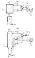
- the device comprises a gas-liquid contactor reactor 1.
- a line 2 supplies the contactor reactor with a sulfur-containing gas charge, for example a effluent from a Claus unit and a line 3 introduces for example a recycled solution comprising a solvent, such as polyethylene glycol 400 and catalyst, such as sodium salicylate.
- the purified gas is evacuated by a line 4.
- a fluid F such as a solvent solution containing at least catalyst, sulfur and by-products formed, is withdrawn from the contactor reactor 1 by a line 5.
- This solution is then sent by a pump 6 and lines 7 and 13 to a zone of treatment 14 where it is rid of the majority of by-products.
- the treatment area 14 comprises at least heating means and separation means, some of which examples are detailed in Figures 3 and 4.
- the heating means are suitable for obtain a temperature which makes it possible to promote the crystallization of the by-products solution in the solvent. All devices known to those skilled in the art and capable of obtaining and to operate at this temperature and in particular allowing the crystallization of the formed by-products previously set out can be used.
- the means for heating the solvent in the treatment zone are suitable for operate in a temperature range between 120 and 180 ° C and preferably between 120 and 150 ° C.
- the treatment zone 14, comprising the means (not shown in this figure) for heating the solvent solution and the means (not shown in this figure) for separating the solvent by-products, has the function in particular of treating the solution F comprising essentially solvent, catalyst, sulfur and by-products, to obtain at least one fluid F 2 comprising the majority of the by-products which is drawn off via line 19, as well as a fluid F 1 composed essentially of solvent practically free of all by-products which is, for example, recycled via line 15 to the contactor reactor 1.
- the fluid F 1 which is in the form of a liquid monophasic solution almost free of by-products is sent by lines 15 and 7 in a heat exchanger 8 where it is cooled to an adequate temperature compatible with the operation of the reactor.
- -contactor 1, for example 120 ° C.
- This temperature can be controlled using a regulator 9 connected to the heat exchanger 8 by a line 10.
- the line 10 is for example in connection with a valve 11 fitted to an inlet line 12 of the coolant in the 'heat exchanger.
- This cooled solvent solution from the heat exchanger 8 can be recycled to the reactor-contactor 1 via line 3.
- the fluid F 2 comprising the majority of the by-products and drawn off through the line 19 is for example diluted in water before being sent to the water treatment.
- the liquid sulfur obtained by decantation is drawn off by a line 18 and located in the lower part of the decantation zone 17, connected to the reactor-contactor 1 by a line 16.
- Line 18 is for example provided with a valve V 1 .
- the chosen temperature range can also allow the solubilization of free sulfur droplets possibly present in the solvent. This has the effect to avoid removing sulfur with the by-products formed and to facilitate treatment any fluid from the regeneration of elements in the treatment area.
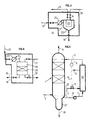
- Figure 2 shows schematically an alternative embodiment for which, the area of settling is integrated into the contactor reactor 1.
- a decantation zone 17 ′ At the lower part of the contactor reactor 1 is a decantation zone 17 ′, provided with an extraction line 18 for liquid sulfur, the line being equipped for example with a valve V 1 in the same way as in the figure 1.
- Part of the single-phase solution of solvent which circulates in the loop recycling (including elements 5, 6, 7, 8, 3), for example 10 to 20% of the solution, is for example taken by a line 40, from line 7, in order to be sent in a treatment zone such as a zone 41 for desaturation of the solvent into sulfur.
- the single-phase solution is cooled, by example at 60 ° C, to form a suspension of sulfur crystals in the solvent.
- This crystallized sulfur is then separated from the solvent by different solid-liquid separation processes known to those skilled in the art, such as filtration, decantation or centrifugation.
- the suspension enriched in solid sulfur can be heated by means suitable known to specialists to melt sulfur and then sent by line 43 in the liquid-liquid settling zone.
- the operating conditions of the process and the device can be the following:
- the reactor-contactor 1 can operate at a temperature for example between 50 and 130 ° C, and preferably between 120 and 122 ° C. Said sulfur formed is in the form liquid. The liquid sulfur formed is very slightly soluble in the solvent and because of its density higher, it settles at the bottom of the reactor. The water formed is discharged with the purified gas. Under these conditions (low temperature and continuous elimination of the products formed), the equilibrium (1) is moved to the right. This temperature is for example regulated by passage of the solvent in the heat exchanger 8.
- the process can be carried out in a very wide pressure range, for example 9.8 kPa to 4.9 MPa. According to an embodiment, the operation is carried out under pressure atmospheric.
- the solvents usually used are mono- or poly-alkylene glycols, esters of mono- or poly-alkylene glycols or ethers of mono- or poly-alkylene glycols as described in the patents FR 2 115 721 (US 3 796 796), FR 2 122 674 and FR 2,138,371 (US 3,832,454).
- the catalysts used are chosen from those mentioned in these same patents and more particularly alkaline salts of weak organic acids such as acid benzoic and salicylic acid.
- the concentration of the catalyst in the liquid phase is advantageously understood between 0.1 and 5% by weight and more advantageously between 0.5 and 2% by weight.
- the method and the device according to the invention are particularly well suited to the treatment of gases having an acid gas content (H 2 S + SO 2 ) of between 0.1 and 100% by volume. It is however particularly advantageous for gases having a low content of acid gases (H 2 S + SO 2 ) for example between 0.1 and 50% by volume and more particularly between 0.5 and 5% by volume.
- the separation step in zone 14 can be carried out in different ways, some are given below by way of illustration and in no way limitative.
- the treatment zone 14 includes heating means 20 and separation means by filtration 22.
- the solvent solution F extracted from the contactor reactor 1 via line 5 is sent by the pump 6 and the lines 7 (FIG. 2) and 13 in the treatment zone 14 comprising a heat exchanger 20 and filtration means, for example one or more filters 22 each consisting for example of at least one filter cartridge 23 with a deformable fabric.
- the solution is reheated in the heat exchanger 20 to a temperature between 120 and 150 ° C. in order to promote the crystallization of the by-products in solution in the solvent and to dissolve the droplets of free sulfur possibly present in the solvent.
- the solution then passes through the filter 22 where the solid by-products are deposited on the cartridge 23 while the purified solvent F 1 is extracted by line 15 in order to be recycled at the head of the reactor-contactor 1.
- the debate of the cartridge 23 to eliminate the solid by-products deposited is done for example by isolating the filter 22 from the rest of the device and sending inside cartridge 23 a fluid, such as filtered solvent or even water, introduced under a pressure slightly higher than atmospheric pressure by a line 24.
- a fluid such as filtered solvent or even water
- the operation of debate can be ordered when the thickness of the cake formed is such that the pressure difference on the filter cartridge becomes high, for example included between 0.1 and 0.4 MPa.
- the by-products in solution in the stripping fluid are extracted at the bottom of the filter by line 19.
- the means for isolating the treatment zone 14 from the rest of the treatment circuit are known to those skilled in the art and are not detailed. They include in particular V 2 isolation valves.
- At least one second filter operating in bypass or in parallel to the first in order to continue to continuously filter the solvent solution during the step debugging of the first filter.
- the separation of the by-products formed is carried out in the treatment zone 14 by capture on a solid support.
- the solvent solution withdrawn from the contactor reactor 1 via line 5 is sent by the pump 6 and the lines 7 (FIG. 2) and 13 in the treatment zone 14 comprising a heat exchanger 20 and capture means, for example one or more capacities 25 each containing one or more collection beds 26.
- Collection beds consist of solids, for example metals, active carbon, zeolites, resins, aluminas, silicas or ceramics.
- the solution is reheated in the heat exchanger 20 to a temperature between 120 and 150 ° C in particular to promote the crystallization of by-products in solution in the solvent and to dissolve the droplets of free sulfur if necessary present in the solvent.
- the solvent solution introduced via line 21 into the capacity 25, passes over the capture bed 26 which traps the by-products.
- the solvent freed from the majority of by-products is extracted from capacity 25 via line 15 to be recycled to the reactor-contactor 1.
- the capacity 25 is isolated. of the rest of the device and passing over the collection bed 26 for example clean water introduced by a line 27.
- the water comes out loaded with dissolved by-products through a line 19.
- the saturation control can be done either by a measurement of the pressure drop on the collection bed either by extrapolating saturation curves established in the laboratory.
- the means making it possible to isolate the treatment zone 14 from the rest of the treatment circuit are known to those skilled in the art and are not detailed. They include in particular V 3 isolation valves.
- salt is used to denote by-products likely to be formed in particular by secondary reactions due to the presence catalyst during a gas treatment process.
- a bottom gas from the Claus unit is introduced via line 2 into a vertical reactor-contactor 1 consisting of a column containing two packing beds, and it is brought into contact. at 125 ° C with an organic solvent containing a soluble catalyst introduced via line 3.
- the padding used for these two examples consists of 2 saddle beds ("Intalox" in ceramic with a specific surface of 250 m 2 / m 3 ).
- the organic solvent used is a polyethylene glycol of molecular mass 400 and the soluble catalyst is sodium salicylate at a concentration of 100 millimoles / kg of solvent.
- the solvent is recycled between the bottom and the top of the reactor-contactor by lines 5, 7 and 3 at a flow rate of 500 m 3 / h, thanks to the circulation pump 6 through a temperature exchanger 8, controlled and regulated in temperature by a measurement-control system 9, 10 and 11 making it possible to inject hot water at 80 ° C into the exchanger via line 12.
- the temperature of the recycled solvent is 125 ° C.
- the purified gas leaves the reactor-contactor via line 4.
- the sulfur formed settles in reactor-contactor bottom and is extracted via line 18 at a rate of 332 kg / h.
- compositions of the inlet and outlet gases of the unit are given in the following table: Constituents Inlet gas (2)% Vol . Exit gas (4)% Vol. H 2 S 1.234 0.0586 SO 2 0.617 0.0293 CO 2 4,000 4.038 COS 0.015 0.009 CS 2 0.015 0.009 S v 0.14 0.03 N 2 60 60,396 H 2 O 34 35,384 Sum of sulfur compounds (counted as sulfur) 2,036 0.1449
- Solution F extracted by line 5 is treated by filtration or by collection in the treatment zone 14 according to the two diagrams set out below.
- Example 1 ( Figures 2 and 3): separation by filtration
- the heat exchanger 20 makes it possible to heat the solvent solution to 135 ° C. and a filter 22 consisting of three cartridges 23, of 1 m 2 of surface each the separation of the two fluids F 1 and F 2 .
- the stripping is done by isolating the treatment zone 14 from the rest of the device and by sending water inside the cartridges under slight pressure through line 24 when the thickness of the cake becomes greater than 3 mm, this is to say when the pressure delta on the filter cartridges becomes greater than 0.2 MPa.
- the salts are recovered in solution in water at the bottom of the filter and sent by line 19 to the water treatment.
- the screening of the filter is done every 12 hours approximately.
- the heat exchanger 20 makes it possible to heat the solvent solution to 135 ° C. and a capacity 25 containing two capture beds 26 of salts of 1 m 3 each in volume of material having good affinity with the salts to be captured. , for example ceramic stools, to separate the two fluids F 1 and F 2 .
- the pressure drop becomes greater than 7 kPa indicating that the collection beds are saturated with salts.
- the treatment zone is then isolated from the rest of the device and the collection beds are regenerated by washing with water which enters clean by line 27 and leaves loaded with salts by line 19 to be sent to the water treatment.
- FIG. 5 shows diagrammatically the process carried out according to the prior art in which the fluid F, or monophasic solution comprising essentially solvent, catalyst, sulfur and by-products, is extracted by line 5 and sent directly to a heat exchanger heat 30 similar to exchanger 8, before being recycled to the reactor-contactor.
- the temperature control is carried out in an identical manner to that given in FIG. 1, with a regulator 9 connected to the heat exchanger 30 by a line 10, the refrigerant being introduced by a line 12 fitted with a valve 11 and discharged by a line 13.
Landscapes
- Chemical & Material Sciences (AREA)
- Engineering & Computer Science (AREA)
- Environmental & Geological Engineering (AREA)
- Organic Chemistry (AREA)
- General Chemical & Material Sciences (AREA)
- Analytical Chemistry (AREA)
- Biomedical Technology (AREA)
- Oil, Petroleum & Natural Gas (AREA)
- Chemical Kinetics & Catalysis (AREA)
- Inorganic Chemistry (AREA)
- Health & Medical Sciences (AREA)
- Treating Waste Gases (AREA)
- Catalysts (AREA)
Abstract
Description
- on favorise la cristallisation des sous-produits en solution dans le solvant, ce qui facilite l'élimination desdits sous-produits,
- on solubilise les gouttelettes de soufre libre éventuellement présentes dans le solvant, ce qui permet d'éviter la co-élimination du soufre avec les sous-produits et facilite l'éventuel traitement du fluide issu de la régénération d'éléments de la zone de traitement
- on extrait après l'étape de mise en contact un fluide F comportant au moins du solvant, du catalyseur, du soufre et des sous-produits,
- on envoie ledit fluide F à une étape de traitement, comportant au moins une étape de chauffage dudit fluide F à une température choisie pour favoriser la cristallisation des sous produits, et une étape de séparation des sous-produits du solvant,
- à l'issue de l'étape de traitement on récupère au moins un fluide F1 composé essentiellement de solvant, de catalyseur et de soufre et quasiment exempt de sous-produits, et un fluide F2 comportant la majorité des sous-produits.
- des moyens de filtration, lesdits moyens étant adaptés pour produire au moins le fluide F1 comportant essentiellement du solvant et au moins le fluide F2 comportant la majorité des sous-produits formés, et/ou
- des moyens de captation, tels que des métaux, des charbons actifs, des zéolithes, des résines, des alumines, des silices ou des céramiques lesdits moyens étant adaptés pour produire au moins le fluide F1 comportant essentiellement du solvant et au moins le fluide F2 comportant la majorité des sous-produits formés.
- d'éviter les problèmes de décantation du soufre liquide dans la zone de décantation liquide-liquide,
- d'éviter l'accumulation de sous-produits solides au niveau des garnissages équipant certains types de réacteurs-contacteurs,
- de pouvoir améliorer simplement les unités Clauspol existantes par une simple adjonction d'un petit nombre d'équipements et donc pour un coût faible,
- de récupérer un solvant purifié et de le recycler directement vers le procédé de traitement des gaz.
- la figure 1 illustre selon un schéma bloc les différents éléments constituant le dispositif selon l'invention, notamment la zone de traitement,
- la figure 2 illustre un dispositif de traitement d'un gaz comportant une zone de décantation située dans la partie inférieure d'un réacteur-contacteur,
- la figure 3 schématise une variante où la zone de traitement est une filtration,
- la figure 4 schématise une variante où la zone de traitement est une masse de captation, et
- la figure 5 représente un schéma de l'art antérieur utilisé à titre d'exemple comparatif.
- Réacteur avec garnissage vrac (par exemple des selles Intalox) ou structuré (par exemple de type Mellapak) commercialisé par exemple par la société Sulzer,
- Mélangeur statique SMV commercialisé par exemple par la société Sulzer,
- Impacteur commercialisé par exemple par la société AEA,
- Hydro-éjecteur commercialisé par exemple par la société Biotrade,
- Atomiseur commercialisé par exemple par la société LAB,
- Contacteur à fils commercialisé par exemple par la société Toussaint Nyssenne.
| Constituants | Gaz entrée (2) % Vol. | Gaz sortie (4) % Vol. |
| H2 S | 1,234 | 0,0586 |
| SO2 | 0,617 | 0,0293 |
| CO2 | 4,000 | 4,038 |
| COS | 0,015 | 0,009 |
| CS2 | 0,015 | 0,009 |
| Sv | 0,14 | 0,03 |
| N2 | 60 | 60,396 |
| H2O | 34 | 35,384 |
| Somme des composés soufrés (comptée en soufre) | 2,036 | 0,1449 |
Claims (11)
- Procédé de traitement d'un gaz contenant au moins de l'hydrogène sulfuré (H2S) et au moins du dioxyde de soufre (SO2) dans lequel on met en contact, à une température adéquate, ledit gaz avec un solvant organique contenant au moins un catalyseur, et où L'on récupère un effluent gazeux ne contenant sensiblement plus d'hydrogène sulfuré et de dioxyde de soufre ainsi que du soufre liquide séparé du solvant par une décantation liquide-liquide, caractérisé en ce que :on extrait après l'étape de mise en contact au moins un fluide F comportant au moins du solvant, du catalyseur, du soufre et des sous-produits,on envoie ledit fluide F à une étape de traitement, comportant au moins une étape de chauffage dudit fluide F à une température choisie pour favoriser la cristallisation des sous-produits et au moins une étape de séparation des sous-produits cristallisés au moins en partie du reste dudit fluide F contenant au moins du solvant,à l'issue de l'étape de traitement on récupère un fluide F1 quasiment exempt de sous-produits et composé essentiellement de solvant, de catalyseur et de soufre, ainsi qu'un fluide F2 comportant la majorité des sous-produits.
- Procédé selon la revendication 1 caractérisé en ce que le fluide F extrait est chauffé au cours de l'étape de traitement à une température comprise avantageusement entre 120 et 180 °C et de préférence entre 120 et 150 °C.
- Procédé selon l'une des revendications 1 et 2 caractérisé en ce que l'étape de séparation des sous-produits est réalisée en mettant en oeuvre au moins un des modes opératoires suivants :a) on réalise au moins une étape de filtration de manière à récupérer au moins le fluide F1 composé essentiellement de solvant, de catalyseur et de soufre, quasiment exempt de sous-produits, et le fluide F2 comportant la majorité des sous-produits après une étape de régénération du support filtrant, et/oub) on effectue au moins une étape de captation des sous-produits sur un support solide de manière à récupérer au moins le fluide F1 composé essentiellement de solvant, de catalyseur et de soufre, quasiment exempt de sous-produits, et le fluide F2 comportant la majorité des sous-produits après une étape de régénération du support solide,
- Procédé selon l'une des revendications 1 à 3 caractérisé en ce qu'on recycle en partie ou en totalité le fluide F1, tel que du solvant épuré au moins en majorité des sous-produits vers l'étape de mise en contact.
- Dispositif permettant d'éliminer et de récupérer des sous-produits formés au cours d'un procédé de traitement d'un effluent gazeux contenant au moins de l'hydrogène sulfuré (H2S) et du dioxyde de soufre (SO2) dans lequel on utilise un solvant organique et au moins un catalyseur, ledit dispositif comportant au moins un réacteur-contacteur (1), au moins une zone de décantation (17), plusieurs lignes (2, 3) d'introduction d'au moins un gaz à traiter, d'un fluide comportant au moins du solvant et du catalyseur, plusieurs lignes (4, 5) d'extraction d'au moins un gaz épuré et d'un fluide F comportant au moins du solvant, du catalyseur, du soufre et des sous-produits, caractérisé en ce qu'il comporte au moins une zone (14) de traitement dudit fluide F comportant au moins du solvant, du catalyseur, du soufre et des sous-produits, ladite zone de traitement comportant des moyens (20) de chauffage adaptés pour favoriser la cristallisation des sous-produits et des moyens de séparation (22 ou 25) adaptés à séparer les sous-produits du reste dudit fluide comportant au moins du solvant, du catalyseur et du soufre, et on récupère en sortie de ladite zone de traitement au moins un fluide F1 composé essentiellement de solvant, de catalyseur et de soufre et quasiment exempt de sous-produits, et un fluide F2 comportant la majorité des sous-produits.
- Dispositif selon la revendication 5 caractérisée en ce que les moyens de chauffage (20) opèrent par exemple entre 120 et 180 °C et de préférence entre 120 et 150 °C.
- Dispositif selon l'une des revendication 5 et 6 caractérisé en ce que la zone de décantation (17) est située dans la partie inférieure dudit réacteur-contacteur (1).
- Dispositif selon les revendication 5 à 7 caractérisé en ce que la zone de traitement peut comporter au moins un des moyens choisis parmi les suivants :des moyens de filtration, lesdits moyens étant adaptés pour produire au moins le fluide F1 comportant essentiellement du solvant et quasiment exempt de sous-produits, et au moins le fluide F2 comportant la majorité des sous-produits formés, et/oudes moyens de captation, tels que des métaux, des charbons actifs, des zéolithes, des résines, des alumines, des silices ou des céramiques lesdits moyens étant adaptés pour produire au moins le fluide F1 comportant essentiellement du solvant et quasiment exempt de sous-produits, et au moins le fluide F2 comportant la majorité des sous-produits formés.
- Dispositif selon l'une des revendications 5 à 8 caractérisé en ce qu'il comporte une ligne de recyclage d'une partie au moins du solvant issu de l'étape de traitement vers le réacteur-contacteur.
- Dispositif selon l'une des revendications 5 à 9 caractérisé en ce que ledit réacteur-contacteur est choisi parmi un des dispositifs donnés dans la liste suivante : réacteur avec garnissage vrac ou structuré ou mélangeur statique SMV ou impacteur ou hydro-éjecteur ou atomiseur ou contacteur à fils.
- Application du procédé selon l'une des revendications 1 à 4 et du dispositif selon l'une des revendications 5 à 10 pour le traitement des effluents d'unités Claus traitant de l'H2S issu d'opérations d'épuration du gaz naturel ou de raffinage du pétrole brut.
Applications Claiming Priority (2)
| Application Number | Priority Date | Filing Date | Title |
|---|---|---|---|
| FR9814674 | 1998-11-20 | ||
| FR9814674A FR2786111B1 (fr) | 1998-11-20 | 1998-11-20 | Procede et dispositif de traitement d'un gaz contenant de l'hydrogene sulfure et du dioxyde de soufre, comportant une etape d'elimination de sous-produits |
Publications (2)
| Publication Number | Publication Date |
|---|---|
| EP1002763A1 true EP1002763A1 (fr) | 2000-05-24 |
| EP1002763B1 EP1002763B1 (fr) | 2007-08-29 |
Family
ID=9533027
Family Applications (1)
| Application Number | Title | Priority Date | Filing Date |
|---|---|---|---|
| EP99402534A Expired - Lifetime EP1002763B1 (fr) | 1998-11-20 | 1999-10-14 | Procédé et dispositif de traitement d'un gaz contenant de l'hydrogène sulfuré et du dioxyde de soufre, comportant une étape d'élimination de sous-produits |
Country Status (6)
| Country | Link |
|---|---|
| US (2) | US6280698B1 (fr) |
| EP (1) | EP1002763B1 (fr) |
| JP (1) | JP4731647B2 (fr) |
| CA (1) | CA2290143C (fr) |
| DE (1) | DE69936964T2 (fr) |
| FR (1) | FR2786111B1 (fr) |
Cited By (2)
| Publication number | Priority date | Publication date | Assignee | Title |
|---|---|---|---|---|
| CN103203152A (zh) * | 2013-03-28 | 2013-07-17 | 郭红妹 | 一种脱硫除尘设备 |
| CN104085860A (zh) * | 2014-03-28 | 2014-10-08 | 中石化南京工程有限公司 | 硫磺回收装置硫池尾气处理装置 |
Families Citing this family (6)
| Publication number | Priority date | Publication date | Assignee | Title |
|---|---|---|---|---|
| FR2882942B1 (fr) | 2005-03-09 | 2007-06-15 | Inst Francais Du Petrole | Procede perfectionne de traitement d'un gaz contenant de l'hydrogene sulfure et du dioxyde de soufre |
| CN105597509B (zh) * | 2015-12-28 | 2018-07-03 | 史晓波 | 污染气体净化装置 |
| CN107661688A (zh) * | 2016-07-27 | 2018-02-06 | 深圳市中核海得威生物科技有限公司 | 一种用于13c‑尿素合成的尾气收集装置 |
| CN109579434A (zh) * | 2018-12-11 | 2019-04-05 | 浙江大学 | 一种利用外循环气波制冷回收聚烯烃装置排放气的方法 |
| CN114788978B (zh) * | 2022-05-07 | 2024-04-12 | 长沙有色冶金设计研究院有限公司 | 一种新型加压浸出工艺尾气处理装置及方法 |
| CN115400533B (zh) * | 2022-08-23 | 2023-06-30 | 天津绿菱气体有限公司 | 一种羰基硫尾气回收利用的方法和装置 |
Citations (4)
| Publication number | Priority date | Publication date | Assignee | Title |
|---|---|---|---|---|
| FR2358186A2 (fr) * | 1976-07-12 | 1978-02-10 | Raffinage Cie Francaise | Procede d'elimination de l'hydrogene sulfure contenu dans des melanges gazeux |
| FR2532190A1 (fr) * | 1982-08-25 | 1984-03-02 | Raffinage Cie Francaise | Dispositif pour l'elimination a froid de l'hydrogene sulfure contenu dans un melange gazeux, par reaction sur de l'anhydride sulfureux, et pour la separation du soufre solide ainsi produit |
| US4565678A (en) * | 1984-12-10 | 1986-01-21 | Conoco Inc. | Method of reducing sulfur oxide and nitrogen oxide content of flue gas |
| FR2735460A1 (fr) * | 1995-06-15 | 1996-12-20 | Inst Francais Du Petrole | Procede et dispositif de traitement d'un gaz contenant de l'hydrogene sulfure, comportant une etape d'elimination du soufre cristallise par refroidissement |
Family Cites Families (6)
| Publication number | Priority date | Publication date | Assignee | Title |
|---|---|---|---|---|
| US4387037A (en) * | 1980-11-24 | 1983-06-07 | Trentham Corporation | Removal of sulfur from waste gas streams |
| DE3208695A1 (de) * | 1982-03-11 | 1983-09-22 | Basf Ag, 6700 Ludwigshafen | Verfahren zur entschwefelung von h(pfeil abwaerts)2(pfeil abwaerts)s-haltigen gasen |
| US5389351A (en) * | 1992-11-04 | 1995-02-14 | Hasebe; Nobuyasu | Method for desulfurizing a gas |
| FR2753396B1 (fr) * | 1996-09-16 | 1998-10-30 | Inst Francais Du Petrole | Procede et dispositif de traitement d'un gaz contenant de l'hydrogene sulfure et du dioxyde de soufre comportant une etape d'appauvrissement en soufre du solvant recycle |
| FR2753395B1 (fr) * | 1996-09-16 | 1998-11-06 | Inst Francais Du Petrole | Procede et dispositif de traitement d'un gaz contenant de l'hydrogene sulfure et de l'anhydride sulfureux, comportant une etape d'elimination du soufre par refroidissement de l'effluent gazeux |
| FR2757147B1 (fr) * | 1996-12-12 | 1999-01-29 | Inst Francais Du Petrole | Procede et dispositif d'epuration d'un gaz contenant de l'hydrogene sulfure et du dioxyde de soufre |
-
1998
- 1998-11-20 FR FR9814674A patent/FR2786111B1/fr not_active Expired - Fee Related
-
1999
- 1999-10-14 DE DE69936964T patent/DE69936964T2/de not_active Expired - Lifetime
- 1999-10-14 EP EP99402534A patent/EP1002763B1/fr not_active Expired - Lifetime
- 1999-11-16 CA CA002290143A patent/CA2290143C/fr not_active Expired - Fee Related
- 1999-11-19 JP JP32974899A patent/JP4731647B2/ja not_active Expired - Fee Related
- 1999-11-22 US US09/444,847 patent/US6280698B1/en not_active Expired - Lifetime
-
2001
- 2001-07-11 US US09/902,104 patent/US6872368B2/en not_active Expired - Fee Related
Patent Citations (4)
| Publication number | Priority date | Publication date | Assignee | Title |
|---|---|---|---|---|
| FR2358186A2 (fr) * | 1976-07-12 | 1978-02-10 | Raffinage Cie Francaise | Procede d'elimination de l'hydrogene sulfure contenu dans des melanges gazeux |
| FR2532190A1 (fr) * | 1982-08-25 | 1984-03-02 | Raffinage Cie Francaise | Dispositif pour l'elimination a froid de l'hydrogene sulfure contenu dans un melange gazeux, par reaction sur de l'anhydride sulfureux, et pour la separation du soufre solide ainsi produit |
| US4565678A (en) * | 1984-12-10 | 1986-01-21 | Conoco Inc. | Method of reducing sulfur oxide and nitrogen oxide content of flue gas |
| FR2735460A1 (fr) * | 1995-06-15 | 1996-12-20 | Inst Francais Du Petrole | Procede et dispositif de traitement d'un gaz contenant de l'hydrogene sulfure, comportant une etape d'elimination du soufre cristallise par refroidissement |
Cited By (2)
| Publication number | Priority date | Publication date | Assignee | Title |
|---|---|---|---|---|
| CN103203152A (zh) * | 2013-03-28 | 2013-07-17 | 郭红妹 | 一种脱硫除尘设备 |
| CN104085860A (zh) * | 2014-03-28 | 2014-10-08 | 中石化南京工程有限公司 | 硫磺回收装置硫池尾气处理装置 |
Also Published As
| Publication number | Publication date |
|---|---|
| DE69936964D1 (de) | 2007-10-11 |
| FR2786111B1 (fr) | 2000-12-15 |
| US6280698B1 (en) | 2001-08-28 |
| CA2290143A1 (fr) | 2000-05-20 |
| FR2786111A1 (fr) | 2000-05-26 |
| US20010055549A1 (en) | 2001-12-27 |
| US6872368B2 (en) | 2005-03-29 |
| DE69936964T2 (de) | 2008-06-26 |
| JP2000159510A (ja) | 2000-06-13 |
| CA2290143C (fr) | 2009-09-29 |
| EP1002763B1 (fr) | 2007-08-29 |
| JP4731647B2 (ja) | 2011-07-27 |
Similar Documents
| Publication | Publication Date | Title |
|---|---|---|
| CA2214424C (fr) | Procede et dispositif de traitement d'un gaz contenant de l'hydrogene sulfure et du dioxyde de soufre comportant une etape d'appauvrissement en soufre du solvant recycle | |
| LU83463A1 (fr) | Procede pour la separation selective d'hydrogene sulfure a partir de melanges gazeux contenant egalement du gaz carbonique | |
| FR2881732A1 (fr) | Procede pour la purification de chlorure d'hydrogene | |
| FR2794665A1 (fr) | Procede et dispositif de traitement d'un gaz contenant de l'hydrogene sulfure, comportant une etape de regeneration de la solution catalytique au moyen d'un ejecteur | |
| EP1002763B1 (fr) | Procédé et dispositif de traitement d'un gaz contenant de l'hydrogène sulfuré et du dioxyde de soufre, comportant une étape d'élimination de sous-produits | |
| EP0992454B1 (fr) | Procédé et dispositif de traitement d'un gaz contenant de l'hydrogène sulfuré et du dioxyde de soufre, comportant une étape d'elimination de sous-produits solides | |
| EP0829452B1 (fr) | Procédé et dispositif de traitement d'un gaz contenant de l'hydrogène sulfuré et de l'anhydride sulfureux, comportant une étape d'élimination du soufre par réfroidissement de l'effluent gazeux | |
| EP0832039B1 (fr) | Procede et dispositif de traitement d'un gaz contenant de l'hydrogene sulfure, comportant une etape d'elimination du soufre cristallise par refroidissement | |
| FR2873711A1 (fr) | Procede de capture des mercaptans contenus dans une charge gazeuse | |
| EP1059111B1 (fr) | Procédé et dispositif de traitement d'un gaz contenant de l'hydrogène sulfuré, avec recyclage de la solution catalytique reduite | |
| EP0922669B1 (fr) | Procédé de récupération du soufre à haute pression | |
| CA2222356C (fr) | Procede et dispositif d'epuration d'un gaz contenant de l'hydrogene sulfure et du dioxyde de soufre | |
| FR2896509A1 (fr) | Procede de capture des mercaptans contenus dans un gaz naturel par concentration. | |
| EP1216957B1 (fr) | Procédé de purification du soufre | |
| EP1450935A1 (fr) | Procede de separation d'un melange gazeux par une unite membranaire de permeation | |
| FR2941630A1 (fr) | Procede et dispositif de desulfuration d'un gaz, comprenant une etape d'elimination du soufre par refroidissement d'un flux gazeux | |
| KR20010013496A (ko) | 산성 가스 용매 여과 시스템 | |
| BE841230A (fr) | Procede pour la separation de composants gazeux | |
| BE901355A (fr) | Procede de purification de charges d'hydrocarbures liquides. |
Legal Events
| Date | Code | Title | Description |
|---|---|---|---|
| PUAI | Public reference made under article 153(3) epc to a published international application that has entered the european phase |
Free format text: ORIGINAL CODE: 0009012 |
|
| AK | Designated contracting states |
Kind code of ref document: A1 Designated state(s): BE DE GB IT NL |
|
| AX | Request for extension of the european patent |
Free format text: AL;LT;LV;MK;RO;SI |
|
| 17P | Request for examination filed |
Effective date: 20001124 |
|
| AKX | Designation fees paid |
Free format text: BE DE GB IT NL |
|
| 17Q | First examination report despatched |
Effective date: 20011112 |
|
| GRAP | Despatch of communication of intention to grant a patent |
Free format text: ORIGINAL CODE: EPIDOSNIGR1 |
|
| GRAS | Grant fee paid |
Free format text: ORIGINAL CODE: EPIDOSNIGR3 |
|
| GRAA | (expected) grant |
Free format text: ORIGINAL CODE: 0009210 |
|
| AK | Designated contracting states |
Kind code of ref document: B1 Designated state(s): BE DE GB IT NL |
|
| REG | Reference to a national code |
Ref country code: GB Ref legal event code: FG4D Free format text: NOT ENGLISH |
|
| REF | Corresponds to: |
Ref document number: 69936964 Country of ref document: DE Date of ref document: 20071011 Kind code of ref document: P |
|
| GBT | Gb: translation of ep patent filed (gb section 77(6)(a)/1977) |
Effective date: 20071128 |
|
| PLBE | No opposition filed within time limit |
Free format text: ORIGINAL CODE: 0009261 |
|
| STAA | Information on the status of an ep patent application or granted ep patent |
Free format text: STATUS: NO OPPOSITION FILED WITHIN TIME LIMIT |
|
| 26N | No opposition filed |
Effective date: 20080530 |
|
| REG | Reference to a national code |
Ref country code: DE Ref legal event code: R081 Ref document number: 69936964 Country of ref document: DE Owner name: IFP ENERGIES NOUVELLES, FR Free format text: FORMER OWNER: INSTITUT FRANCAIS DU PETROLE, RUEIL MALMAISON, FR Effective date: 20110331 |
|
| PGFP | Annual fee paid to national office [announced via postgrant information from national office to epo] |
Ref country code: DE Payment date: 20141023 Year of fee payment: 16 Ref country code: GB Payment date: 20141022 Year of fee payment: 16 |
|
| PGFP | Annual fee paid to national office [announced via postgrant information from national office to epo] |
Ref country code: NL Payment date: 20141020 Year of fee payment: 16 |
|
| PGFP | Annual fee paid to national office [announced via postgrant information from national office to epo] |
Ref country code: IT Payment date: 20141022 Year of fee payment: 16 |
|
| PGFP | Annual fee paid to national office [announced via postgrant information from national office to epo] |
Ref country code: BE Payment date: 20141022 Year of fee payment: 16 |
|
| REG | Reference to a national code |
Ref country code: DE Ref legal event code: R119 Ref document number: 69936964 Country of ref document: DE |
|
| GBPC | Gb: european patent ceased through non-payment of renewal fee |
Effective date: 20151014 |
|
| REG | Reference to a national code |
Ref country code: NL Ref legal event code: MM Effective date: 20151101 |
|
| PG25 | Lapsed in a contracting state [announced via postgrant information from national office to epo] |
Ref country code: GB Free format text: LAPSE BECAUSE OF NON-PAYMENT OF DUE FEES Effective date: 20151014 Ref country code: DE Free format text: LAPSE BECAUSE OF NON-PAYMENT OF DUE FEES Effective date: 20160503 Ref country code: IT Free format text: LAPSE BECAUSE OF NON-PAYMENT OF DUE FEES Effective date: 20151014 |
|
| PG25 | Lapsed in a contracting state [announced via postgrant information from national office to epo] |
Ref country code: NL Free format text: LAPSE BECAUSE OF NON-PAYMENT OF DUE FEES Effective date: 20151101 |
|
| PG25 | Lapsed in a contracting state [announced via postgrant information from national office to epo] |
Ref country code: BE Free format text: LAPSE BECAUSE OF NON-PAYMENT OF DUE FEES Effective date: 20151031 |