EP1002912A1 - Verfahren zur elektrischen Kontaktierung von Betonarmierungen - Google Patents
Verfahren zur elektrischen Kontaktierung von Betonarmierungen Download PDFInfo
- Publication number
- EP1002912A1 EP1002912A1 EP99122377A EP99122377A EP1002912A1 EP 1002912 A1 EP1002912 A1 EP 1002912A1 EP 99122377 A EP99122377 A EP 99122377A EP 99122377 A EP99122377 A EP 99122377A EP 1002912 A1 EP1002912 A1 EP 1002912A1
- Authority
- EP
- European Patent Office
- Prior art keywords
- concrete
- borehole
- threaded rod
- metal reinforcement
- metal
- Prior art date
- Legal status (The legal status is an assumption and is not a legal conclusion. Google has not performed a legal analysis and makes no representation as to the accuracy of the status listed.)
- Granted
Links
- 238000004519 manufacturing process Methods 0.000 title claims description 3
- 239000002184 metal Substances 0.000 claims abstract description 27
- 229910052751 metal Inorganic materials 0.000 claims abstract description 27
- 239000004567 concrete Substances 0.000 claims abstract description 25
- 230000002787 reinforcement Effects 0.000 claims abstract description 24
- 238000000034 method Methods 0.000 claims abstract description 19
- 238000005259 measurement Methods 0.000 claims 1
- 239000007769 metal material Substances 0.000 claims 1
- XEEYBQQBJWHFJM-UHFFFAOYSA-N Iron Chemical compound [Fe] XEEYBQQBJWHFJM-UHFFFAOYSA-N 0.000 description 12
- 229910052742 iron Inorganic materials 0.000 description 6
- 239000000956 alloy Substances 0.000 description 2
- 229910045601 alloy Inorganic materials 0.000 description 2
- 229910001369 Brass Inorganic materials 0.000 description 1
- 230000006978 adaptation Effects 0.000 description 1
- 238000004873 anchoring Methods 0.000 description 1
- 239000010951 brass Substances 0.000 description 1
- 238000005266 casting Methods 0.000 description 1
- 238000010276 construction Methods 0.000 description 1
- 230000007797 corrosion Effects 0.000 description 1
- 238000005260 corrosion Methods 0.000 description 1
- 230000006735 deficit Effects 0.000 description 1
- 238000005553 drilling Methods 0.000 description 1
- 238000010616 electrical installation Methods 0.000 description 1
- 238000005516 engineering process Methods 0.000 description 1
- 238000011065 in-situ storage Methods 0.000 description 1
- 239000000463 material Substances 0.000 description 1
- 239000011150 reinforced concrete Substances 0.000 description 1
- 230000003716 rejuvenation Effects 0.000 description 1
- 238000009420 retrofitting Methods 0.000 description 1
- 238000000926 separation method Methods 0.000 description 1
Images
Classifications
-
- H—ELECTRICITY
- H05—ELECTRIC TECHNIQUES NOT OTHERWISE PROVIDED FOR
- H05K—PRINTED CIRCUITS; CASINGS OR CONSTRUCTIONAL DETAILS OF ELECTRIC APPARATUS; MANUFACTURE OF ASSEMBLAGES OF ELECTRICAL COMPONENTS
- H05K9/00—Screening of apparatus or components against electric or magnetic fields
- H05K9/0001—Rooms or chambers
-
- E—FIXED CONSTRUCTIONS
- E04—BUILDING
- E04C—STRUCTURAL ELEMENTS; BUILDING MATERIALS
- E04C5/00—Reinforcing elements, e.g. for concrete; Auxiliary elements therefor
Definitions
- the present invention relates to a method for the electrical contacting of Metal reinforcements in concrete.
- the present invention has for its object to provide a method for electrical contacting of metal reinforcements in concrete, which can be carried out with little economic effort and in particular avoids freeing and subsequent casting of the concrete surface.
- the invention proposes a method for electrical contacting of metal reinforcements in concrete, the position of the metal reinforcement in concrete being determined, a borehole extending up to the metal reinforcement being produced in the concrete, anchoring a threaded rod in the borehole by means of an expansion anchor and until the electrically conductive contact with the metal reinforcement is screwed in.
- the method according to the invention avoids prying open Arrangement of a hole in which an expansion plug is placed, in which again a threaded rod is inserted.
- the metal reinforcement in the concrete first located using an iron seeker and the position of the Probation iron marked. A well is then drilled down to the iron. Then the borehole with an undercut cone area made and completely cleaned. Through the borehole is now Metal reinforcement metallic free. It is then placed in an expansion anchor Screw in the threaded rod until the dowel begins to spread. Then the Inserted assembly into the drill hole and the threaded rod in the expansion plug screwed in until it contacts the metal reinforcement. The threaded rod is now anchored in the borehole, can be cut to length and electrically connected.
- the dowel is advantageously a metal dowel that is in one Direction of use has a tapering inner diameter to a corresponding to produce good spread.
- this measure will Screwing in the threaded rod destroys the thread on the tapered area, see above that an independent release is hindered.
- Threaded rods in the sense of the invention can be threaded screws, Machine screws or simple threaded metal bars be understood.
- Expansion anchors are preferably metallic anchors that over are slotted part of their length, so when turning the Spread out the threaded rod. It is advantageous when screwing in Threaded rod to measure electrical resistance.
- the borehole can be installed before the electrical Connection to be sealed by hosing to make a subsequent Prevent moisture ingress.
- the invention provides a device for electrical contacting, consisting of an internal thread, preferably metallic expansion anchors with tapering in the direction of use Essentially inside diameter and a metallic threaded rod constant diameter.
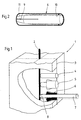
- FIG. 1 shows a schematic concrete area 1, in which a metal reinforcement 2 is led.
- a metal reinforcement 2 is led.
- an iron detector on the concrete surface located until the metal armouring was found to match the position of the Mark the iron with a mark 3. It then becomes a borehole 4 manufactured, which extends to the probation and for example one Has a diameter of 8 mm.
- a larger drill bit for example 10 mm, a bore 5 with an undercut cone and then cleaned the hole.
- Metal dowels come into consideration as dowels, for example with one Outside diameter of 10 mm and a minimum length of 25 mm. As metal come preferably iron and its alloys and brass and its Alloys in question. Inside, the dowel has an M8 thread, for example and has at least 3 regularly distributed over the scope, but a maximum of 8 incisions of approximately 1.4 mm distributed regularly over the circumference. The thread is, for example, tapered and protrudes at least 6 mm through the Incisions formed into segments. The segment thickness at the end of the anchor is at least 2 mm, maximum 2.8 mm. An embodiment for a dowel is shown in Figure 2, where the dowel 6 has a long threaded area 10 uniform diameter and a tapered diameter range 11 has, which is in the region of the incisions 9.
- Such an anchor is connected with a threaded rod.
- the Threaded screw, machine screw or threaded rod 7 is in the dowel 6 screwed in until it begins to spread in the front area. Then the assembly is inserted into borehole 5 and the threaded rod turned into the dowel.
- a resistance measuring device a ⁇ meter, not shown, the resistance between an existing one Potential rail or suitable mass and the threaded rod or machine screw measured.
- the resistance value assumes low ohmic values, for example less than 10 ohms Threaded rod or machine screw turned as far as possible, manually and without tools, so as not to close the thread overwind or damage other elements.
- the threaded rod is cut to length and electrically contacted be, for example by nuts, cable lugs, lock washers and the like.
- the threaded rod 7 contacting the probation in the area 8 now creates the electrical connection.
Landscapes
- Engineering & Computer Science (AREA)
- Architecture (AREA)
- Microelectronics & Electronic Packaging (AREA)
- Civil Engineering (AREA)
- Structural Engineering (AREA)
- Reinforcement Elements For Buildings (AREA)
- Prevention Of Electric Corrosion (AREA)
- Electrical Discharge Machining, Electrochemical Machining, And Combined Machining (AREA)
Abstract
Description
- Fig. 1
- eine schematische Darstellung eines metallarmierten Betonbereiches mit unterschiedlichen Verfahrenssituationen und
- Fig. 2
- eine Darstellung eines Ausführungsbeispiels für einen Spreizdübel.
- 1
- Beton
- 2
- Bewährung
- 3
- Markierung
- 4
- Bohrung
- 5
- erweiterte Bohrung
- 6
- Spreizdübel
- 7
- Gewindestange
- 8
- Kontaktbereich
- 9
- Einschnitt
- 10
- Gewindebereich
- 11
- Verjüngung
Claims (10)
- Verfahren zur elektrischen Kontaktierung von Metallarmierungen in Beton, wobeidie Position der Metallarmierung in Beton festgestellt wird,ein bis zur Metallarmierung verlaufendes Bohrloch im Beton hergestellt wird,im Bohrloch eine Gewindestange mittels eines Spreizdübels verankert undbis zur elektrisch leitenden Kontaktierung mit der Metallarmierung eingeschraubt wird.
- Verfahren nach Anspruch 1, dadurch gekennzeichnet, daß ein Spreizdübel mit Innengewinde verwendet wird.
- Verfahren nach einem der vorhergehenden Ansprüche, dadurch gekennzeichnet, daß ein Spreizdübel mit in Einsatzrichtung sich verjüngendem Innendurchmesser verwendet wird.
- Verfahren nach einem der vorgehenden Ansprüche, dadurch gekennzeichnet, daß ein aus metallischem Werkstoff bestehender Spreizdübel verwendet wird.
- Verfahren nach einem der vorhergehenden Ansprüche, dadurch gekennzeichnet, daß das Bohrloch mit einem in Richtung der Metallarmierung hinterschnittenen Erweiterungsbereich ausgebildet wird.
- Verfahren nach Anspruch 5, dadurch gekennzeichnet, daß der Erweiterungsbereich konisch ausgeführt wird.
- Verfahren nach einem der vorhergehenden Ansprüche, dadurch gekennzeichnet, daß bei der Herstellung der elektrisch leitenden Kontaktierung eine Widerstandsmessung durchgeführt wird.
- Verfahren nach einem der vorhergehenden Ansprüche, dadurch gekennzeichnet, daß das Bohrloch feuchtigkeitsdicht abgedichtet wird.
- Verfahren nach einem der vorgehenden Ansprüche, dadurch gekennzeichnet, daß die Gewindestangen außerhalb des Bohrloches elektrisch angeschlossen wird.
- Vorrichtung zur elektrischen Kontaktierung von Metallarmierungen in Beton nach dem Verfahren nach einem der Ansprüche 1 bis 9, bestehend aus einem mit einem Innengewinde versehenen Spreizdübel mit sich in Einsatzrichtung verjüngendem Innendurchmesser und einer metallischen Gewindestange mit im wesentlichen konstantem Durchmesser.
Applications Claiming Priority (2)
| Application Number | Priority Date | Filing Date | Title |
|---|---|---|---|
| DE19853332A DE19853332C1 (de) | 1998-11-19 | 1998-11-19 | Verfahren zur elektrischen Kontaktierung von Betonarmierungen |
| DE19853332 | 1998-11-19 |
Publications (2)
| Publication Number | Publication Date |
|---|---|
| EP1002912A1 true EP1002912A1 (de) | 2000-05-24 |
| EP1002912B1 EP1002912B1 (de) | 2005-07-06 |
Family
ID=7888313
Family Applications (1)
| Application Number | Title | Priority Date | Filing Date |
|---|---|---|---|
| EP99122377A Expired - Lifetime EP1002912B1 (de) | 1998-11-19 | 1999-11-10 | Verfahren zur elektrischen Kontaktierung von Betonarmierungen |
Country Status (6)
| Country | Link |
|---|---|
| EP (1) | EP1002912B1 (de) |
| AT (1) | ATE299213T1 (de) |
| CA (1) | CA2351483A1 (de) |
| DE (2) | DE19853332C1 (de) |
| ES (1) | ES2245068T3 (de) |
| WO (1) | WO2000029692A1 (de) |
Cited By (1)
| Publication number | Priority date | Publication date | Assignee | Title |
|---|---|---|---|---|
| US6850651B2 (en) | 2001-07-02 | 2005-02-01 | Corel Corporation | Moiré correction in images |
Citations (7)
| Publication number | Priority date | Publication date | Assignee | Title |
|---|---|---|---|---|
| US2793245A (en) * | 1953-01-21 | 1957-05-21 | Ace Engineering & Machine Co I | Radio shielded enclosures |
| US4520521A (en) * | 1982-12-02 | 1985-06-04 | Akira Miyake | Process of manufacturing a sleeve and wedge for an anchor bolt |
| FR2611829A1 (fr) * | 1987-03-03 | 1988-09-09 | Campenon Bernard Btp | Procede et dispositif pour realiser un ancrage dans un massif |
| EP0291597A1 (de) * | 1987-05-22 | 1988-11-23 | SHIMIZU CONSTRUCTION Co. LTD. | Verfahren zum elektromagnetischen Abschirmen von Gebäuden |
| DE4103216A1 (de) * | 1991-02-02 | 1992-08-06 | Hilti Ag | Einrichtung zum auffinden magnetisierbaren materials in bauwerken |
| WO1994004474A1 (en) * | 1992-08-26 | 1994-03-03 | John Philip Broomfield | Electrochemical stabilisation of mineral masses such as concrete, and electrode arrangements therefor |
| DE4341329A1 (de) * | 1993-12-03 | 1995-06-08 | Leonhard Nasl | Eingußdübel |
Family Cites Families (2)
| Publication number | Priority date | Publication date | Assignee | Title |
|---|---|---|---|---|
| DE3406664A1 (de) * | 1984-02-24 | 1985-09-05 | Albert 4270 Dorsten Stewing | Kabelkanal |
| DE4027020C2 (de) * | 1990-08-27 | 1994-08-25 | Heinrich Liebig Gmbh | Verfahren und Vorrichtung zur Feststellung des Vorhandenseins von metallischen Bewehrungselementen im Innern eines Beton-Bauteils |
-
1998
- 1998-11-19 DE DE19853332A patent/DE19853332C1/de not_active Expired - Fee Related
-
1999
- 1999-11-10 AT AT99122377T patent/ATE299213T1/de not_active IP Right Cessation
- 1999-11-10 ES ES99122377T patent/ES2245068T3/es not_active Expired - Lifetime
- 1999-11-10 CA CA002351483A patent/CA2351483A1/en not_active Abandoned
- 1999-11-10 DE DE59912236T patent/DE59912236D1/de not_active Expired - Fee Related
- 1999-11-10 EP EP99122377A patent/EP1002912B1/de not_active Expired - Lifetime
- 1999-11-10 WO PCT/EP1999/008611 patent/WO2000029692A1/de not_active Ceased
Patent Citations (7)
| Publication number | Priority date | Publication date | Assignee | Title |
|---|---|---|---|---|
| US2793245A (en) * | 1953-01-21 | 1957-05-21 | Ace Engineering & Machine Co I | Radio shielded enclosures |
| US4520521A (en) * | 1982-12-02 | 1985-06-04 | Akira Miyake | Process of manufacturing a sleeve and wedge for an anchor bolt |
| FR2611829A1 (fr) * | 1987-03-03 | 1988-09-09 | Campenon Bernard Btp | Procede et dispositif pour realiser un ancrage dans un massif |
| EP0291597A1 (de) * | 1987-05-22 | 1988-11-23 | SHIMIZU CONSTRUCTION Co. LTD. | Verfahren zum elektromagnetischen Abschirmen von Gebäuden |
| DE4103216A1 (de) * | 1991-02-02 | 1992-08-06 | Hilti Ag | Einrichtung zum auffinden magnetisierbaren materials in bauwerken |
| WO1994004474A1 (en) * | 1992-08-26 | 1994-03-03 | John Philip Broomfield | Electrochemical stabilisation of mineral masses such as concrete, and electrode arrangements therefor |
| DE4341329A1 (de) * | 1993-12-03 | 1995-06-08 | Leonhard Nasl | Eingußdübel |
Non-Patent Citations (2)
| Title |
|---|
| BUNGEY J: "NON-DESTRUCTIVE TESTING FOR REINFORCEMENT CORROSION", CONCRETE,GB,CEMENT AND CONCRETE ASSOCIATION. LONDON, vol. 27, no. 1, 1 January 1993 (1993-01-01), pages 16 - 18, XP000336625, ISSN: 0010-5317 * |
| ROWLAND P W: "INDUSTRIAL SYSTEM GROUNDING FOR POWER, STATIC, LIGHTNING AND INSTRUMENTATION, PRACTICAL APPLICATIONS", IEEE TRANSACTIONS ON INDUSTRY APPLICATIONS,US,IEEE INC. NEW YORK, VOL. 31, NR. 6, PAGE(S) 1I-6I, ISSN: 0093-9994, XP000555148 * |
Cited By (2)
| Publication number | Priority date | Publication date | Assignee | Title |
|---|---|---|---|---|
| US6850651B2 (en) | 2001-07-02 | 2005-02-01 | Corel Corporation | Moiré correction in images |
| US7050651B2 (en) | 2001-07-02 | 2006-05-23 | Corel Corporation | Moiré correction in images |
Also Published As
| Publication number | Publication date |
|---|---|
| EP1002912B1 (de) | 2005-07-06 |
| WO2000029692A1 (de) | 2000-05-25 |
| ES2245068T3 (es) | 2005-12-16 |
| DE19853332C1 (de) | 2000-09-07 |
| DE59912236D1 (de) | 2005-08-11 |
| CA2351483A1 (en) | 2000-05-25 |
| ATE299213T1 (de) | 2005-07-15 |
Similar Documents
| Publication | Publication Date | Title |
|---|---|---|
| DE102005022449A1 (de) | Abstandshalter für die Befestigung eines Gegenstandes an einem eine Dämmschicht aufweisenden Untergrund | |
| WO2000028225A1 (de) | Gewindeschneidende schraube | |
| EP0955476A2 (de) | Selbstschneidende Schraube zum Einsatz in Vollbaustoffen | |
| EP2250380A1 (de) | System aus verbundankerschraube und klebstoff | |
| DE19706510C1 (de) | Elektrodenbaugruppe für ein Korrosionsmeßsystem zum Feststellen von Korrosion von in einem Bauteil aus einem ionenleitendem Baustoff, insbesondere Beton, eingebettetem Metall | |
| DE19938363A1 (de) | Schraubanker | |
| DE102006000539A1 (de) | Befestigungselement | |
| EP1710453B1 (de) | Befestigungs-Anker | |
| EP1760331B1 (de) | Befestigungselement für harte Untergründe | |
| DE19749571B4 (de) | Ankervorrichtung zur Befestigung von dynamisch querbelasteten Gegenständen | |
| DE19853332C1 (de) | Verfahren zur elektrischen Kontaktierung von Betonarmierungen | |
| DE102006017459A1 (de) | Abstandshalter für die Befestigung eines Gegenstandes an einem eine Dämmschicht aufweisenden Untergrund | |
| DE19944217A1 (de) | Bolzenanker | |
| DE102008030051B4 (de) | Ankerstange zur Verankerung in einem Bohrloch | |
| EP1680606B1 (de) | Befestigungselement | |
| DE102007044981B4 (de) | Tragkonstruktion und Verfahren zum Verankern von Tragkonstruktionen | |
| EP0338466B1 (de) | Gleisanschlussbolzen | |
| DE4032682C2 (de) | Gebirgsanker | |
| DE3934531A1 (de) | Stabanker zum fuegen von staeben | |
| DE2744829C2 (de) | Rohrlänge für Arbeiten in Tiefbohrungen und Verfahren zu ihrer Herstellung | |
| DE4408159C2 (de) | Verfahren zum Einbringen eines Dübels in Porenbeton | |
| AT396152B (de) | Huellrohr fuer einen bewehrungsstab aus stahl | |
| DE3312293C2 (de) | Vorrichtung zum Befestigen eines Klettergerüstes an Betonwänden | |
| DE3631544A1 (de) | Verfahren zum verankern von bauteilen in insbesondere beton | |
| DE3338559A1 (de) | Verfahren zur befestigung eines koppelbolzens in einem stein und vorrichtungen zur durchfuehrung dieses verfahrens |
Legal Events
| Date | Code | Title | Description |
|---|---|---|---|
| PUAI | Public reference made under article 153(3) epc to a published international application that has entered the european phase |
Free format text: ORIGINAL CODE: 0009012 |
|
| AK | Designated contracting states |
Kind code of ref document: A1 Designated state(s): AT BE CH CY DE DK ES FI FR GB GR IE IT LI LU MC NL PT SE |
|
| AX | Request for extension of the european patent |
Free format text: AL;LT;LV;MK;RO;SI |
|
| 17P | Request for examination filed |
Effective date: 20001111 |
|
| AKX | Designation fees paid |
Free format text: AT BE CH CY DE DK ES FI FR GB GR IE IT LI LU MC NL PT SE |
|
| 17Q | First examination report despatched |
Effective date: 20030224 |
|
| GRAP | Despatch of communication of intention to grant a patent |
Free format text: ORIGINAL CODE: EPIDOSNIGR1 |
|
| GRAS | Grant fee paid |
Free format text: ORIGINAL CODE: EPIDOSNIGR3 |
|
| GRAA | (expected) grant |
Free format text: ORIGINAL CODE: 0009210 |
|
| AK | Designated contracting states |
Kind code of ref document: B1 Designated state(s): AT BE CH CY DE DK ES FI FR GB GR IE IT LI LU MC NL PT SE |
|
| PG25 | Lapsed in a contracting state [announced via postgrant information from national office to epo] |
Ref country code: IE Free format text: LAPSE BECAUSE OF FAILURE TO SUBMIT A TRANSLATION OF THE DESCRIPTION OR TO PAY THE FEE WITHIN THE PRESCRIBED TIME-LIMIT Effective date: 20050706 |
|
| REG | Reference to a national code |
Ref country code: GB Ref legal event code: FG4D Free format text: NOT ENGLISH |
|
| REG | Reference to a national code |
Ref country code: CH Ref legal event code: NV Representative=s name: E. BLUM & CO. PATENTANWAELTE Ref country code: CH Ref legal event code: EP |
|
| REG | Reference to a national code |
Ref country code: IE Ref legal event code: FG4D Free format text: LANGUAGE OF EP DOCUMENT: GERMAN |
|
| REF | Corresponds to: |
Ref document number: 59912236 Country of ref document: DE Date of ref document: 20050811 Kind code of ref document: P |
|
| PG25 | Lapsed in a contracting state [announced via postgrant information from national office to epo] |
Ref country code: GR Free format text: LAPSE BECAUSE OF FAILURE TO SUBMIT A TRANSLATION OF THE DESCRIPTION OR TO PAY THE FEE WITHIN THE PRESCRIBED TIME-LIMIT Effective date: 20051006 Ref country code: DK Free format text: LAPSE BECAUSE OF FAILURE TO SUBMIT A TRANSLATION OF THE DESCRIPTION OR TO PAY THE FEE WITHIN THE PRESCRIBED TIME-LIMIT Effective date: 20051006 |
|
| GBT | Gb: translation of ep patent filed (gb section 77(6)(a)/1977) |
Effective date: 20050926 |
|
| REG | Reference to a national code |
Ref country code: SE Ref legal event code: TRGR |
|
| PG25 | Lapsed in a contracting state [announced via postgrant information from national office to epo] |
Ref country code: CY Free format text: LAPSE BECAUSE OF FAILURE TO SUBMIT A TRANSLATION OF THE DESCRIPTION OR TO PAY THE FEE WITHIN THE PRESCRIBED TIME-LIMIT Effective date: 20051110 |
|
| PG25 | Lapsed in a contracting state [announced via postgrant information from national office to epo] |
Ref country code: MC Free format text: LAPSE BECAUSE OF NON-PAYMENT OF DUE FEES Effective date: 20051130 Ref country code: LU Free format text: LAPSE BECAUSE OF NON-PAYMENT OF DUE FEES Effective date: 20051130 |
|
| PG25 | Lapsed in a contracting state [announced via postgrant information from national office to epo] |
Ref country code: PT Free format text: LAPSE BECAUSE OF FAILURE TO SUBMIT A TRANSLATION OF THE DESCRIPTION OR TO PAY THE FEE WITHIN THE PRESCRIBED TIME-LIMIT Effective date: 20051212 |
|
| REG | Reference to a national code |
Ref country code: ES Ref legal event code: FG2A Ref document number: 2245068 Country of ref document: ES Kind code of ref document: T3 |
|
| REG | Reference to a national code |
Ref country code: IE Ref legal event code: FD4D |
|
| ET | Fr: translation filed | ||
| PLBE | No opposition filed within time limit |
Free format text: ORIGINAL CODE: 0009261 |
|
| STAA | Information on the status of an ep patent application or granted ep patent |
Free format text: STATUS: NO OPPOSITION FILED WITHIN TIME LIMIT |
|
| PG25 | Lapsed in a contracting state [announced via postgrant information from national office to epo] |
Ref country code: DE Free format text: LAPSE BECAUSE OF NON-PAYMENT OF DUE FEES Effective date: 20060601 |
|
| 26N | No opposition filed |
Effective date: 20060407 |
|
| PGFP | Annual fee paid to national office [announced via postgrant information from national office to epo] |
Ref country code: GB Payment date: 20061107 Year of fee payment: 8 |
|
| PGFP | Annual fee paid to national office [announced via postgrant information from national office to epo] |
Ref country code: IT Payment date: 20061130 Year of fee payment: 8 |
|
| REG | Reference to a national code |
Ref country code: CH Ref legal event code: PFA Owner name: PFEIL, GERHARD Free format text: PFEIL, GERHARD#AM DEICH 53#21723 HOLLERN-TWIELENFLETH (DE) -TRANSFER TO- PFEIL, GERHARD#AM DEICH 53#21723 HOLLERN-TWIELENFLETH (DE) |
|
| GBPC | Gb: european patent ceased through non-payment of renewal fee |
Effective date: 20071110 |
|
| PG25 | Lapsed in a contracting state [announced via postgrant information from national office to epo] |
Ref country code: GB Free format text: LAPSE BECAUSE OF NON-PAYMENT OF DUE FEES Effective date: 20071110 |
|
| PGFP | Annual fee paid to national office [announced via postgrant information from national office to epo] |
Ref country code: FI Payment date: 20081210 Year of fee payment: 10 Ref country code: AT Payment date: 20081118 Year of fee payment: 10 |
|
| PGFP | Annual fee paid to national office [announced via postgrant information from national office to epo] |
Ref country code: SE Payment date: 20081119 Year of fee payment: 10 |
|
| PG25 | Lapsed in a contracting state [announced via postgrant information from national office to epo] |
Ref country code: IT Free format text: LAPSE BECAUSE OF NON-PAYMENT OF DUE FEES Effective date: 20071110 |
|
| EUG | Se: european patent has lapsed | ||
| PG25 | Lapsed in a contracting state [announced via postgrant information from national office to epo] |
Ref country code: FI Free format text: LAPSE BECAUSE OF NON-PAYMENT OF DUE FEES Effective date: 20091110 Ref country code: AT Free format text: LAPSE BECAUSE OF NON-PAYMENT OF DUE FEES Effective date: 20091110 |
|
| PG25 | Lapsed in a contracting state [announced via postgrant information from national office to epo] |
Ref country code: SE Free format text: LAPSE BECAUSE OF NON-PAYMENT OF DUE FEES Effective date: 20091111 |
|
| PGFP | Annual fee paid to national office [announced via postgrant information from national office to epo] |
Ref country code: ES Payment date: 20101130 Year of fee payment: 12 |
|
| PGFP | Annual fee paid to national office [announced via postgrant information from national office to epo] |
Ref country code: NL Payment date: 20110531 Year of fee payment: 12 |
|
| REG | Reference to a national code |
Ref country code: NL Ref legal event code: V1 Effective date: 20120601 |
|
| PG25 | Lapsed in a contracting state [announced via postgrant information from national office to epo] |
Ref country code: NL Free format text: LAPSE BECAUSE OF NON-PAYMENT OF DUE FEES Effective date: 20120601 |
|
| REG | Reference to a national code |
Ref country code: ES Ref legal event code: FD2A Effective date: 20131029 |
|
| PG25 | Lapsed in a contracting state [announced via postgrant information from national office to epo] |
Ref country code: ES Free format text: LAPSE BECAUSE OF NON-PAYMENT OF DUE FEES Effective date: 20111111 |
|
| REG | Reference to a national code |
Ref country code: FR Ref legal event code: PLFP Year of fee payment: 17 |
|
| REG | Reference to a national code |
Ref country code: FR Ref legal event code: PLFP Year of fee payment: 18 |
|
| REG | Reference to a national code |
Ref country code: FR Ref legal event code: PLFP Year of fee payment: 19 |
|
| PGFP | Annual fee paid to national office [announced via postgrant information from national office to epo] |
Ref country code: FR Payment date: 20171027 Year of fee payment: 19 |
|
| PGFP | Annual fee paid to national office [announced via postgrant information from national office to epo] |
Ref country code: BE Payment date: 20171027 Year of fee payment: 19 Ref country code: CH Payment date: 20171027 Year of fee payment: 19 |
|
| REG | Reference to a national code |
Ref country code: CH Ref legal event code: PL |
|
| REG | Reference to a national code |
Ref country code: BE Ref legal event code: MM Effective date: 20181130 |
|
| PG25 | Lapsed in a contracting state [announced via postgrant information from national office to epo] |
Ref country code: LI Free format text: LAPSE BECAUSE OF NON-PAYMENT OF DUE FEES Effective date: 20181130 Ref country code: CH Free format text: LAPSE BECAUSE OF NON-PAYMENT OF DUE FEES Effective date: 20181130 |
|
| PG25 | Lapsed in a contracting state [announced via postgrant information from national office to epo] |
Ref country code: FR Free format text: LAPSE BECAUSE OF NON-PAYMENT OF DUE FEES Effective date: 20181130 |
|
| PG25 | Lapsed in a contracting state [announced via postgrant information from national office to epo] |
Ref country code: BE Free format text: LAPSE BECAUSE OF NON-PAYMENT OF DUE FEES Effective date: 20181130 |