EP1002929A1 - Versetzte Anordnung von Führungsspalt und von den Führungsschienen bei Rolläden - Google Patents
Versetzte Anordnung von Führungsspalt und von den Führungsschienen bei Rolläden Download PDFInfo
- Publication number
- EP1002929A1 EP1002929A1 EP99450027A EP99450027A EP1002929A1 EP 1002929 A1 EP1002929 A1 EP 1002929A1 EP 99450027 A EP99450027 A EP 99450027A EP 99450027 A EP99450027 A EP 99450027A EP 1002929 A1 EP1002929 A1 EP 1002929A1
- Authority
- EP
- European Patent Office
- Prior art keywords
- deck
- slot
- roller shutter
- box
- apron
- Prior art date
- Legal status (The legal status is an assumption and is not a legal conclusion. Google has not performed a legal analysis and makes no representation as to the accuracy of the status listed.)
- Withdrawn
Links
- 238000004804 winding Methods 0.000 claims abstract description 19
- 230000000295 complement effect Effects 0.000 claims description 4
- 230000000712 assembly Effects 0.000 description 2
- 238000000429 assembly Methods 0.000 description 2
- 230000001627 detrimental effect Effects 0.000 description 2
- 238000001125 extrusion Methods 0.000 description 2
- 238000009413 insulation Methods 0.000 description 2
- 238000004519 manufacturing process Methods 0.000 description 2
- 238000005096 rolling process Methods 0.000 description 2
- 238000011001 backwashing Methods 0.000 description 1
- 230000007423 decrease Effects 0.000 description 1
- 229920001971 elastomer Polymers 0.000 description 1
- 239000000806 elastomer Substances 0.000 description 1
- 230000010354 integration Effects 0.000 description 1
- 239000000463 material Substances 0.000 description 1
- 238000010422 painting Methods 0.000 description 1
Images

Classifications
-
- E—FIXED CONSTRUCTIONS
- E06—DOORS, WINDOWS, SHUTTERS, OR ROLLER BLINDS IN GENERAL; LADDERS
- E06B—FIXED OR MOVABLE CLOSURES FOR OPENINGS IN BUILDINGS, VEHICLES, FENCES OR LIKE ENCLOSURES IN GENERAL, e.g. DOORS, WINDOWS, BLINDS, GATES
- E06B9/00—Screening or protective devices for wall or similar openings, with or without operating or securing mechanisms; Closures of similar construction
- E06B9/02—Shutters, movable grilles, or other safety closing devices, e.g. against burglary
- E06B9/08—Roll-type closures
- E06B9/11—Roller shutters
- E06B9/17—Parts or details of roller shutters, e.g. suspension devices, shutter boxes, wicket doors, ventilation openings
- E06B9/17061—Connection of the box to the guides
Definitions
- the present invention relates to an offset arrangement of the slot passage and behind the scenes of a rolling shutter with a leaf deck.
- roller shutters that allow the concealment of a opening generally comprising a carpentry. We hear for the rest of the description by carpentry any frame with a door or a window or any other opening.
- shutters have blades hinged together which constitute an apron, this apron being designed to be wound on a tree arranged in a box.
- the tree is maneuvered by a gear driven either manually by a crank or, more and more often, by an electric motor.
- This actuation means has the advantage, in addition to the ease of maneuver, to connect the engine control to a programming system.
- the apron can thus take, apart from all positions intermediate, two extreme positions, one completely high position wrapped in which the opening is completely unobstructed and a position fully unrolled bass in which the opening is completely obscured.
- the apron comes out of the box through a passage slot, the final blade of the apron being equipped with means for abutting against the box so to avoid putting this final blade in the box, thus preventing the exit of the apron.
- the diameter of the shaft therefore changes from a substantially nominal diameter d to a diameter D in the upper position of the deck.
- the box is of square section with one face flat top to press against the lintel of the opening, one side inner and outer face also flat to press against the plane of the opening or to be parallel to the wall which carries it in the case of a integration and a flat underside also to be parallel to the plane of the lintel.
- the underside carries the apron passage slot.
- This slot is arranged as close as possible to one of the angles of the box, that is to say in the vertical plane tangent to the winding of the deck in the high position, of diameter D.
- this embodiment makes it possible to initiate the descent of the deck without friction on the edge of the slot because at the beginning of the unwinding, the apron is suspended and its weight does not intervene.
- the apron is guided in its descent by slides, added against the opening paintings. These slides are aligned vertically under the slot and limit friction by additional means like brushes or elastomer seals that hold the deck in place middle position in each slide to prevent this apron from touching the backstage edges.
- the arrangement according to the invention aims to overcome these problems of prior art assemblies to allow the production of boxes which have rounded, symmetrical shapes that allow movement easy winding and unrolling of the apron, which requires substantially a constant effort for an engine in the best conditions, which ensure a simple and watertight abutment of the slot, which integrate the guiding means in the cheeks in order to simplify the manufacture of the boxes and which leave room for the exterior handles of the joinery in the case of a external mounting of the box, while pressing the box against the carpentry.
- the rolling shutter according to the invention comprises a casing forming a box, a winding shaft of an apron comprising articulated blades, said shaft being provided with maneuvering means in rotation about its axis of rotation, a slot of passage of this deck formed in the casing and of the slides aligned under this slot for guiding, and is characterized in that the passage slot and the slides are offset by a value d towards the axis of rotation, c ' ie substantially from the vertical plane P tangent to the theoretical maximum winding of the deck and the vertical plane passing through this axis of rotation.
- This flap further comprises a guide stop, formed in the casing of the box, outside the apron relative to the direction of winding of the apron.
- This guide stop has an open S- profile and its two ends have vertical asymptotes.
- the roller shutter includes a boss additional guide arranged on the inside of the apron relative to the winding direction of the deck.
- the shutter box comprises two cheeks which each carry a guide stop and / or a boss complementary guidance.
- the apron comprises a final blade provided of two curved wings whose profile is adapted to cooperate with the casing of the box and to completely block the passage slot and to form stop.
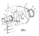
- FIG. 1 a cheek 10, a shaft support 12 and means 14 for fixing this support to the cheek.
- a box housing 16 17 is shown in broken lines which surround the cheek 10 and the entire rolled-up apron 18 and its winding mechanism, not shown because of known type and not part of the present invention.
- the casing has a slot 20 for passing the bulkhead.
- the cheek 10 is secured to the shaft support 12 by means of a ring 24.
- a guide stop 26 attached to the cheek and preferably come from extrusion with it, because the cheek is made of material plastic by extrusion.
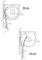
- This guide stop 26 begins at the point of tangency of the vertical plane P with the deck in its theoretical maximum winding position and extends to the edge of the slot 20. Note that this stop has upper and lower ends which emerge in vertical asymptotes to limit friction in remaining substantially parallel to the apron blades.
- the stop 26 is associated with guide, a complementary guide boss 28 disposed on the edge opposite of the slot
- This boss has the function of allowing guidance and good unfolding of the apron when this apron is almost completely unrolled and that the last blades come into contact with the corresponding lip of the slot.
- the radius of curvature of this boss is adapted so that the straight line which is tangent to the tree be tangent also to said boss.
- the slides 30 are arranged, if necessary, in the vertical alignment of the slot 20 and are offset by a value d relative to the joinery.
- the final blade 32 includes two inner wings 34 and external 36, curved and provided in dimensions as in radius of curvature to follow the shape of the casing 16 of the box 17. This blade seals the perfectly slits and serves as a distributed stop.
- the final blade, in the stop position, is positioned parallel to the slides, ready to descend and guide the deck, even if the slides are offset relative to the box.
Landscapes
- Engineering & Computer Science (AREA)
- Structural Engineering (AREA)
- Architecture (AREA)
- Civil Engineering (AREA)
- Operating, Guiding And Securing Of Roll- Type Closing Members (AREA)
Applications Claiming Priority (2)
| Application Number | Priority Date | Filing Date | Title |
|---|---|---|---|
| FR9814677A FR2785940B1 (fr) | 1998-11-18 | 1998-11-18 | Agencement decale de la pente de passage et des coulisses d'un volet roulant a tablier a lames |
| FR9814677 | 1998-11-18 |
Publications (1)
| Publication Number | Publication Date |
|---|---|
| EP1002929A1 true EP1002929A1 (de) | 2000-05-24 |
Family
ID=9533030
Family Applications (1)
| Application Number | Title | Priority Date | Filing Date |
|---|---|---|---|
| EP99450027A Withdrawn EP1002929A1 (de) | 1998-11-18 | 1999-11-17 | Versetzte Anordnung von Führungsspalt und von den Führungsschienen bei Rolläden |
Country Status (2)
| Country | Link |
|---|---|
| EP (1) | EP1002929A1 (de) |
| FR (1) | FR2785940B1 (de) |
Citations (7)
| Publication number | Priority date | Publication date | Assignee | Title |
|---|---|---|---|---|
| CH118399A (de) * | 1926-04-03 | 1927-05-02 | Wilh Baumann | Lagerungseinrichtung für die Walze von Rolladen, Rolljalousien und dergleichen. |
| DE3511473A1 (de) * | 1985-03-29 | 1986-10-09 | Armin 4630 Bochum Besler | Rolladen-endstab mit den auslassschlitz im rolladenkasten abdichtender dichtung |
| DE3537301A1 (de) * | 1985-10-19 | 1987-04-23 | Hans Ziegler | Rolladen |
| DE3811901A1 (de) * | 1988-04-09 | 1990-01-11 | Heim & Haus Vertrieb | Rolladen |
| EP0702126A1 (de) * | 1994-09-06 | 1996-03-20 | Franz Kraler | Rolladen |
| DE4440778A1 (de) * | 1994-11-15 | 1996-05-23 | Armin Besler | Bestandteil von auf Blendrahmen aufsetzbaren Rolladenkästen bildende Wange mit an ihrer Innenseite angesetztem Gurtrollengehäuse |
| DE19521752A1 (de) * | 1995-06-14 | 1996-12-19 | D & M Rolladentechnik Gmbh | Rolladenkasten |
-
1998
- 1998-11-18 FR FR9814677A patent/FR2785940B1/fr not_active Expired - Fee Related
-
1999
- 1999-11-17 EP EP99450027A patent/EP1002929A1/de not_active Withdrawn
Patent Citations (7)
| Publication number | Priority date | Publication date | Assignee | Title |
|---|---|---|---|---|
| CH118399A (de) * | 1926-04-03 | 1927-05-02 | Wilh Baumann | Lagerungseinrichtung für die Walze von Rolladen, Rolljalousien und dergleichen. |
| DE3511473A1 (de) * | 1985-03-29 | 1986-10-09 | Armin 4630 Bochum Besler | Rolladen-endstab mit den auslassschlitz im rolladenkasten abdichtender dichtung |
| DE3537301A1 (de) * | 1985-10-19 | 1987-04-23 | Hans Ziegler | Rolladen |
| DE3811901A1 (de) * | 1988-04-09 | 1990-01-11 | Heim & Haus Vertrieb | Rolladen |
| EP0702126A1 (de) * | 1994-09-06 | 1996-03-20 | Franz Kraler | Rolladen |
| DE4440778A1 (de) * | 1994-11-15 | 1996-05-23 | Armin Besler | Bestandteil von auf Blendrahmen aufsetzbaren Rolladenkästen bildende Wange mit an ihrer Innenseite angesetztem Gurtrollengehäuse |
| DE19521752A1 (de) * | 1995-06-14 | 1996-12-19 | D & M Rolladentechnik Gmbh | Rolladenkasten |
Also Published As
| Publication number | Publication date |
|---|---|
| FR2785940A1 (fr) | 2000-05-19 |
| FR2785940B1 (fr) | 2001-01-12 |
Similar Documents
| Publication | Publication Date | Title |
|---|---|---|
| EP0272733A1 (de) | Rolltorvorrichtung | |
| EP0207040B1 (de) | Vorrichtung zum Schützen von Glasbauten gegen Sonnenstrahlen | |
| EP0500499A1 (de) | Store | |
| EP2844817B1 (de) | Schliess- oder sonnenschutzeinrichtung und verfahren zur realisierung eine der einrichtungen | |
| EP1122403B1 (de) | Vorrichtung zur Begrenzung des Weges eines Rolladenpanzers | |
| EP3263826B1 (de) | Rollladen mit verstellbaren lamellen | |
| FR2614929A1 (fr) | Tablier pour volet roulant | |
| FR2785940A1 (fr) | Agencement decale de la pente de passage et des coulisses d'un volet roulant a tablier a lames | |
| EP1030027A1 (de) | In zwei Teile geteilter Rolladen mit variablem Fenster | |
| LU86627A1 (fr) | Volet roulant pour fenetre de toiture | |
| FR2533617A1 (fr) | Volet roulant | |
| FR2804156A1 (fr) | Dispositif de connexion entre un caisson de volet roulant et une glissiere de guidage | |
| FR2765616A1 (fr) | Perfectionnements a des volets roulants | |
| EP1260135A1 (de) | Vorrichtung zum reversiblen Abdecken eines Gewächshausdaches mit einer Plane | |
| EP3263822B1 (de) | Haustechnikanlage | |
| FR2873400A1 (fr) | Ensemble de lames articulees, tablier de volet roulant et volet roulant ainsi forme | |
| FR3053720B1 (fr) | Store a lames orientables | |
| FR2614928A1 (fr) | Volet roulant pour porte, fenetre et autres ouvertures | |
| EP0976908A1 (de) | Rafflamellenstore | |
| BE525986A (de) | ||
| FR2788552A1 (fr) | Dispositif d'entrainement et d'equilibrage motorise d'un ouvrant | |
| FR2486583A1 (fr) | Volets pliants pare-soleil | |
| EP3263821A1 (de) | Heimtechnikanlage und verfahren zur inbetriebnahme dieser anlage | |
| FR2778943A1 (fr) | Dispositif de manoeuvre pour volet roulant ou analogue et volet roulant equipe d'un tel dispositif | |
| FR2869941A1 (fr) | Empilage de lames de volet dans la partie superieure d'une baie |
Legal Events
| Date | Code | Title | Description |
|---|---|---|---|
| PUAI | Public reference made under article 153(3) epc to a published international application that has entered the european phase |
Free format text: ORIGINAL CODE: 0009012 |
|
| AK | Designated contracting states |
Kind code of ref document: A1 Designated state(s): AT BE CH CY DE DK ES FI FR GB GR IE IT LI LU MC NL PT SE |
|
| AX | Request for extension of the european patent |
Free format text: AL;LT;LV;MK;RO;SI |
|
| AKX | Designation fees paid | ||
| STAA | Information on the status of an ep patent application or granted ep patent |
Free format text: STATUS: THE APPLICATION IS DEEMED TO BE WITHDRAWN |
|
| 18D | Application deemed to be withdrawn |
Effective date: 20001127 |