EP1002931B1 - Seitlicher Führungswagen für Sektionaltore mit vertikaler Öffnung - Google Patents
Seitlicher Führungswagen für Sektionaltore mit vertikaler Öffnung Download PDFInfo
- Publication number
- EP1002931B1 EP1002931B1 EP99390023A EP99390023A EP1002931B1 EP 1002931 B1 EP1002931 B1 EP 1002931B1 EP 99390023 A EP99390023 A EP 99390023A EP 99390023 A EP99390023 A EP 99390023A EP 1002931 B1 EP1002931 B1 EP 1002931B1
- Authority
- EP
- European Patent Office
- Prior art keywords
- drum
- sleeve
- bearing
- lateral guide
- roller
- Prior art date
- Legal status (The legal status is an assumption and is not a legal conclusion. Google has not performed a legal analysis and makes no representation as to the accuracy of the status listed.)
- Expired - Lifetime
Links
Images



Classifications
-
- E—FIXED CONSTRUCTIONS
- E05—LOCKS; KEYS; WINDOW OR DOOR FITTINGS; SAFES
- E05D—HINGES OR SUSPENSION DEVICES FOR DOORS, WINDOWS OR WINGS
- E05D15/00—Suspension arrangements for wings
- E05D15/16—Suspension arrangements for wings for wings sliding vertically more or less in their own plane
- E05D15/165—Details, e.g. sliding or rolling guides
-
- E—FIXED CONSTRUCTIONS
- E05—LOCKS; KEYS; WINDOW OR DOOR FITTINGS; SAFES
- E05D—HINGES OR SUSPENSION DEVICES FOR DOORS, WINDOWS OR WINGS
- E05D15/00—Suspension arrangements for wings
- E05D15/16—Suspension arrangements for wings for wings sliding vertically more or less in their own plane
- E05D15/24—Suspension arrangements for wings for wings sliding vertically more or less in their own plane consisting of parts connected at their edges
- E05D15/242—Hinge connections between the parts
-
- E—FIXED CONSTRUCTIONS
- E05—LOCKS; KEYS; WINDOW OR DOOR FITTINGS; SAFES
- E05Y—INDEXING SCHEME ASSOCIATED WITH SUBCLASSES E05D AND E05F, RELATING TO CONSTRUCTION ELEMENTS, ELECTRIC CONTROL, POWER SUPPLY, POWER SIGNAL OR TRANSMISSION, USER INTERFACES, MOUNTING OR COUPLING, DETAILS, ACCESSORIES, AUXILIARY OPERATIONS NOT OTHERWISE PROVIDED FOR, APPLICATION THEREOF
- E05Y2201/00—Constructional elements; Accessories therefor
- E05Y2201/20—Brakes; Disengaging means; Holders; Stops; Valves; Accessories therefor
- E05Y2201/218—Holders
- E05Y2201/22—Locks
-
- E—FIXED CONSTRUCTIONS
- E05—LOCKS; KEYS; WINDOW OR DOOR FITTINGS; SAFES
- E05Y—INDEXING SCHEME ASSOCIATED WITH SUBCLASSES E05D AND E05F, RELATING TO CONSTRUCTION ELEMENTS, ELECTRIC CONTROL, POWER SUPPLY, POWER SIGNAL OR TRANSMISSION, USER INTERFACES, MOUNTING OR COUPLING, DETAILS, ACCESSORIES, AUXILIARY OPERATIONS NOT OTHERWISE PROVIDED FOR, APPLICATION THEREOF
- E05Y2201/00—Constructional elements; Accessories therefor
- E05Y2201/60—Suspension or transmission members; Accessories therefor
- E05Y2201/622—Suspension or transmission members elements
- E05Y2201/638—Cams; Ramps
-
- E—FIXED CONSTRUCTIONS
- E05—LOCKS; KEYS; WINDOW OR DOOR FITTINGS; SAFES
- E05Y—INDEXING SCHEME ASSOCIATED WITH SUBCLASSES E05D AND E05F, RELATING TO CONSTRUCTION ELEMENTS, ELECTRIC CONTROL, POWER SUPPLY, POWER SIGNAL OR TRANSMISSION, USER INTERFACES, MOUNTING OR COUPLING, DETAILS, ACCESSORIES, AUXILIARY OPERATIONS NOT OTHERWISE PROVIDED FOR, APPLICATION THEREOF
- E05Y2201/00—Constructional elements; Accessories therefor
- E05Y2201/60—Suspension or transmission members; Accessories therefor
- E05Y2201/622—Suspension or transmission members elements
- E05Y2201/684—Rails; Tracks
-
- E—FIXED CONSTRUCTIONS
- E05—LOCKS; KEYS; WINDOW OR DOOR FITTINGS; SAFES
- E05Y—INDEXING SCHEME ASSOCIATED WITH SUBCLASSES E05D AND E05F, RELATING TO CONSTRUCTION ELEMENTS, ELECTRIC CONTROL, POWER SUPPLY, POWER SIGNAL OR TRANSMISSION, USER INTERFACES, MOUNTING OR COUPLING, DETAILS, ACCESSORIES, AUXILIARY OPERATIONS NOT OTHERWISE PROVIDED FOR, APPLICATION THEREOF
- E05Y2201/00—Constructional elements; Accessories therefor
- E05Y2201/60—Suspension or transmission members; Accessories therefor
- E05Y2201/622—Suspension or transmission members elements
- E05Y2201/688—Rollers
-
- E—FIXED CONSTRUCTIONS
- E05—LOCKS; KEYS; WINDOW OR DOOR FITTINGS; SAFES
- E05Y—INDEXING SCHEME ASSOCIATED WITH SUBCLASSES E05D AND E05F, RELATING TO CONSTRUCTION ELEMENTS, ELECTRIC CONTROL, POWER SUPPLY, POWER SIGNAL OR TRANSMISSION, USER INTERFACES, MOUNTING OR COUPLING, DETAILS, ACCESSORIES, AUXILIARY OPERATIONS NOT OTHERWISE PROVIDED FOR, APPLICATION THEREOF
- E05Y2600/00—Mounting or coupling arrangements for elements provided for in this subclass
- E05Y2600/10—Adjustable
- E05Y2600/20—Adjustable with specific transmission movement
-
- E—FIXED CONSTRUCTIONS
- E05—LOCKS; KEYS; WINDOW OR DOOR FITTINGS; SAFES
- E05Y—INDEXING SCHEME ASSOCIATED WITH SUBCLASSES E05D AND E05F, RELATING TO CONSTRUCTION ELEMENTS, ELECTRIC CONTROL, POWER SUPPLY, POWER SIGNAL OR TRANSMISSION, USER INTERFACES, MOUNTING OR COUPLING, DETAILS, ACCESSORIES, AUXILIARY OPERATIONS NOT OTHERWISE PROVIDED FOR, APPLICATION THEREOF
- E05Y2800/00—Details, accessories and auxiliary operations not otherwise provided for
-
- E—FIXED CONSTRUCTIONS
- E05—LOCKS; KEYS; WINDOW OR DOOR FITTINGS; SAFES
- E05Y—INDEXING SCHEME ASSOCIATED WITH SUBCLASSES E05D AND E05F, RELATING TO CONSTRUCTION ELEMENTS, ELECTRIC CONTROL, POWER SUPPLY, POWER SIGNAL OR TRANSMISSION, USER INTERFACES, MOUNTING OR COUPLING, DETAILS, ACCESSORIES, AUXILIARY OPERATIONS NOT OTHERWISE PROVIDED FOR, APPLICATION THEREOF
- E05Y2800/00—Details, accessories and auxiliary operations not otherwise provided for
- E05Y2800/10—Additional functions
- E05Y2800/12—Sealing
-
- E—FIXED CONSTRUCTIONS
- E05—LOCKS; KEYS; WINDOW OR DOOR FITTINGS; SAFES
- E05Y—INDEXING SCHEME ASSOCIATED WITH SUBCLASSES E05D AND E05F, RELATING TO CONSTRUCTION ELEMENTS, ELECTRIC CONTROL, POWER SUPPLY, POWER SIGNAL OR TRANSMISSION, USER INTERFACES, MOUNTING OR COUPLING, DETAILS, ACCESSORIES, AUXILIARY OPERATIONS NOT OTHERWISE PROVIDED FOR, APPLICATION THEREOF
- E05Y2800/00—Details, accessories and auxiliary operations not otherwise provided for
- E05Y2800/40—Physical or chemical protection
- E05Y2800/412—Physical or chemical protection against friction
-
- E—FIXED CONSTRUCTIONS
- E05—LOCKS; KEYS; WINDOW OR DOOR FITTINGS; SAFES
- E05Y—INDEXING SCHEME ASSOCIATED WITH SUBCLASSES E05D AND E05F, RELATING TO CONSTRUCTION ELEMENTS, ELECTRIC CONTROL, POWER SUPPLY, POWER SIGNAL OR TRANSMISSION, USER INTERFACES, MOUNTING OR COUPLING, DETAILS, ACCESSORIES, AUXILIARY OPERATIONS NOT OTHERWISE PROVIDED FOR, APPLICATION THEREOF
- E05Y2900/00—Application of doors, windows, wings or fittings thereof
- E05Y2900/10—Application of doors, windows, wings or fittings thereof for buildings or parts thereof
- E05Y2900/106—Application of doors, windows, wings or fittings thereof for buildings or parts thereof for garages
Definitions
- the invention relates to a lateral guide carriage for doors. vertical deletion sectionals.
- the vertical sectional doors are, so current, consisting of a plurality of panels hinged together by through hinges, and further comprise side carriages of guide bearing guide rollers adapted to roll in guide rails arranged longitudinally on either side of said sectional door.
- the aforementioned guide rails do not extend vertically but are inclined at an angle of the order of a few degrees (seven degrees in theory) from the vertical so as to avoid the friction of the sectional door against the seals during maneuvers of the latter, and to ensure better sealing in position closed of said sectional door.
- the lateral guide carriages are designed so as to allow adjustment of the position of the guide rollers ensuring a progressive shift of the latter, depending on the inclination of the guide rails.
- the guide carriages typically have a wall portion arranged to extend horizontally and pierced with an extending light orthogonally to the bearing axis.
- the latter is carried by a plate able to be moved on the horizontal wall of the carriage guide and provided, at the base of the light thereof, an orifice allowing secure said plate to the carriage by means of a screw / nut assembly once the positioning of the adjusted roller.
- the present invention aims to overcome the aforementioned drawbacks means for adjusting the position of the guide rollers of the sectional doors, and has as main objective to provide a lateral guide carriage for door sectional allowing very easy adjustment of the position of the guide roller carried by said guide carriage without requiring any tool.
- level intends to define so general any means known per se adapted to support and guide the shaft in rotation bearing the guide roller.
- the adjustment of the position of the roller guidance is obtained very simply by rotating the drum inside the cylindrical sleeve then, once the adjustment has been made, by moving axially said drum so as to bring it into a rotational locking position.
- the bearing housed eccentrically inside said drum is caused to rotate around the axis of this last, so that the distance between the axis of said bearing and the bearing face on the cart body panels varies continuously.
- the adjustment operation can thus be carried out with a single hand without requiring any tool, and lead to an accuracy of positioning only as a function of the precision of the locking means in drum rotation.
- the means of locking in rotation include notches and complementary axial notches formed respectively on the opposite faces of the peripheral walls of the sleeve and drum, from one end of these, so that a notch can enter a notch for rotational locking positions of said drum and sleeve, by driving in the drum inside the sleeve from an adjustment position where said drum is partially extracted from said sleeve.
- the precision of the adjustment obtained is function of the angular distribution of the notches and / or notches formed on the drum and sleeve and can therefore be optimized very easily.
- the notches are advantageously provided on the inner face of the peripheral wall of the sleeve and juxtaposed with each other others around the entire periphery of said peripheral wall, the drum comprising at least one notch formed on the external face of its peripheral wall.
- the drum preferably comprises four notches uniformly distributed around the axis of said drum, in order to guarantee the perfect rotation blocking of this drum.
- the sleeve advantageously comprises two series of notches formed respectively at each end of said sleeve. Therefore, the guide carriage can be fixed on either either side of the sectional door, simply by reversing the direction inserting the drum into the sleeve, so that only one model of carriage guide is required to equip the entire sectional door.
- the means of translation locking of the drum inside the sleeve includes a rim external device formed at the end of the drum provided with notches, able to come into abutment against the sleeve when said drum is pressed in inside said sleeve, and at least one retractable elastic axial tongue radially, provided with an external stop notch against the opposite end of the muff.
- the bearing is preferably attached to the wall drum device so as to obtain a maximum range of adjustment of the position of the guide roller.
- the body of carriage has two portions of concave front walls extending respectively on either side of the sleeve in the continuity of the wall peripheral of the latter, said front wall portions being pierced holes for fixing said carriage body to a door panel Sectional.
- the carriage body preferably constitutes a first element of a hinge provided with a transverse central pivot and a second hinge element having the general shape of a plate capable of being fixed on a sectional door panel.
- the shaft carries roller is a hollow shaft of length greater than that of the bearing, and has a abutment end flange against said bearing, and opposite said flange, an end section with an external diameter less than the current external diameter of said shaft, defining a raceway for the roller, said section end being provided with at least two axial slots delimiting a tongue flexible with an external notch of axial stop of said roller.
- this roller bearing shaft advantageously comprises a pin adapted to be inserted axially and locked in the end section of said shaft, said pin being provided with a collar comprising, for each notch external of said roller bearing shaft, a notch capable of accommodating said notch so as to form with the latter a radial crown of axial stop of the roller.
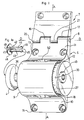
- the guide carriage according to the invention shown in Figures 1 to 5 is suitable to be fixed laterally on adjoining panels 1, 2 a sectional door, and designed, on the one hand, to act as a hinge relative articulation of said panels, and, on the other hand, to guide the sectional door during its operations, being conventionally provided with a roller guide 4 arranged to roll in a lateral guide rail 5 extending longitudinally on the side of said sectional door.
- This guide carriage is, first of all, made up of two separate elements 6, 7 articulated around a central pivot 8 and adapted to be each joined together on a panel 1, 2.
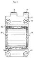
- the first of these elements 6 comprises a sleeve transverse cylindrical 9 extended by two concave wall portions, lower 10 and higher 11, extending in the continuity of the peripheral wall of said sleeve and forming therewith the "carriage body" adapted to be fixed on a panel 1 of the sectional door.
- This carriage body is also closed laterally by side walls such as 12 conforming to the concave profile of the lower 10 and upper 11 wall portions and defining a flat face of support on the sectional door panel 1.
- each of the lower 10 and upper 11 wall portions is pierced with two orifices such as 13, capable of accommodating the head of the fixing screw such as 15.
- the upper wall portion 11 has a bead-shaped upper end consisting of two sleeves 16, 17 coaxial separated by a slot, and forming the connecting socket structure first element 6 and second element 7 of the guide carriage.
- the cylindrical sleeve 9 for its part, comprises two series internal axial notches such as 18, 19 formed respectively from each end face of said cylindrical sleeve, each series of notches 18, 19 consisting of a plurality of juxtaposed notches distributed over the whole the periphery of this cylindrical sleeve 9.
- This second part 9b further comprises two tabs symmetrical deformables such as 50 each extending in the extension of the base of said second part, and each endowed, at their free end, an external hook 51 for ratcheting.
- Each of these tabs 50 is, moreover, arranged at the interior of a light 52 formed in the peripheral wall of the second part 9b, and adapted to allow manual deformation of said tabs in view of the connection and separation of the two parts 9a, 9b forming the cylindrical sleeve 9.
- the cradle 9a comprises, in turn, in the extension of each of the lower 10 and upper 11 portions, a return such as 53, extending tangentially with respect to the end section of said cradle, and adapted to form a locking stop for each hook 51.
- the second element 7 of this guide carriage forms to him a support plate on a sectional door panel 2, extended by bead consisting of two coaxial sleeves 20, 21 separated by a slot forming the nesting structure complementary to that of the first element 6, adapted to accommodate with the latter the pivot 8 of articulation of said elements.
- this pivot 8 consists of a rod 22 with a head 23 and pierced at its end opposite to said head, with a blind axial bore 24 opposite which said rod has two tabs elastic bands such as 25 diametrically opposed, each delimited by two axial slots, and each provided with an external notch such as 26 for locking in translation of the rod 22 inside the sleeves 16, 17, 20, 21.
- the guide carriage according to the invention also comprises a cylindrical drum 27 of dimensions adapted to be inserted and able turn inside the cylindrical sleeve 9.
- This drum 27 first accommodates a cylindrical tube 28 able to accommodate the shaft carrying the guide roller 4, said tube being attached to the wall device of said drum and made in one piece with the latter, so as to be eccentric relative to the axis of the drum 27.
- This drum 27 and, moreover, closed at one of its ends by a circular wall 29 of greater diameter to the external diameter of said drum, so as to delimit on the periphery of the latter an outer peripheral rim of abutment against one of the end faces of the cylindrical sleeve 9.
- this circular wall 29 is pierced with an orifice in the extension of the bearing tube 28.
- the drum 27 further comprises four external notches axial such as 30, 31 attached to the peripheral edge of the circular wall 29 and sections adapted to penetrate each into a notch 18, 19 of the sleeve cylindrical 9, in a position for fully inserting the drum inside said cylindrical sleeve where the circular wall 29 abuts against this cylindrical sleeve 9.
- the drum 27 comprises, finally, opposite the wall circular 29, two deformable bands 32, 33 diametrically opposite, delimited each by two axial slots formed in the peripheral wall of said drum.
- these deformable bands 32, 33 extend partially in the extension of the drum 29 and are each provided, at this extension, an external notch 34, 35 for locking in translation of said drum relative to the cylindrical sleeve 9.
- the guide carriage also includes a hollow shaft 36 on which the guide roller 4 is mounted, adapted to be inserted into the cylindrical tube 28.
- This hollow shaft 36 of length greater than that of the tube 28 has, over its greatest length, an external diameter combined with the diameter internal of said tube, and has an end section 37 of smaller diameter forming the raceway of the guide roller 4.
- This hollow shaft 36 further comprises, at the level of the section end 37, two diametrically opposite deformable bands delimited each by two axial slots and each provided with an external stop 38, 39 axial of the guide roller 4.
- This hollow shaft 36 also comprises, opposite the end section 37, a flange 40 of abutment against the circular wall 29 of the drum 27.
- This hollow shaft 36 comprises, finally, upstream of the section end 37, in the direction of the flange 40, an internal excess thickness delimiting a partial conduit 41 of internal diameter less than the current internal diameter of said hollow tree.
- the guide carriage finally comprises a pin 42 shown in Figure la, arranged to be inserted into the end section 37 of the hollow shaft 36 and adapted to ensure in particular the non-deformability of said end section a times the guide roller 4 placed around it.
- This pin 42 has firstly two legs longitudinal flexible 43, 44 each having an external notch 45, 46, extending in the axial extension of a nozzle 47 of section adapted to be housed in the end section 37 of the hollow shaft 36. These longitudinal tabs 43, 44 are, in further, arranged to snap to the rear of the conduit 41 via notches 45, 46.
- the pin 42 comprises, finally, a flange 48 formed at the level of the end of the end piece 47, and provided with notches 49 capable of accommodating each one of the external notches 38, 39 of the shaft those 36, said flange being arranged for extend in the same radial plane as said external notches so as to form with these an axial abutment crown of the guide roller.
- Such a guide carriage allows, first of all, by a simple rotation of the drum 27 inside the cylindrical sleeve 9, authorized in initially positioning said drum in the position shown in Figure 1 where the notches 30, 31 are released from the notches 18, 19, to adjust the distance separating the axis of rotation of the guide roller 4 of the internal face of the panel 1 corresponding to the sectional door, so as to bring said guide roller to bear against the running face of the guide rail 5.
- Figures 8a and 8b show by way of example the two extreme setting positions "emin” and emax "obtained respectively when the axis of the guide roller 4 and the axis of the drum 27 extend in the same plane horizontal.
- the body of the carriage 9-11 and the second element 7 can be fixed in the factory on panels 1, 2, the connection between said panels can be carried out on site, in situ, by assembling and locking these two elements by means of the central pivot 8.
- the guide roller 4 can be easily inserted into the rail guide 5 without having to unscrew the screws 15 of the cylindrical sleeve 9.
- the two parts 9a, 9b are separated, the drum 27 is placed in the cradle 9a, and the shell 9b finally assembled on said cradle, so as to ensure the final maintenance of said drum.
Landscapes
- Engineering & Computer Science (AREA)
- Mechanical Engineering (AREA)
- Support Devices For Sliding Doors (AREA)
- Operating, Guiding And Securing Of Roll- Type Closing Members (AREA)
- Finish Polishing, Edge Sharpening, And Grinding By Specific Grinding Devices (AREA)
- Mechanical Pencils And Projecting And Retracting Systems Therefor, And Multi-System Writing Instruments (AREA)
- Control And Other Processes For Unpacking Of Materials (AREA)
- Wing Frames And Configurations (AREA)
- Bearings For Parts Moving Linearly (AREA)
- Automobile Manufacture Line, Endless Track Vehicle, Trailer (AREA)
Claims (12)
- Seitlicher Führungswagen für Sektionaltore mit vertikaler Öffnung, die aus einer Mehrzahl von Platten (1, 2) bestehen, die dazwischen um Transversalachsen angelenkt sind, wobei der seitliche Führungswagen Folgendes umfasst:wobei der genannte Führungswagen dadurch gekennzeichnet ist, dass die Mittel zum Regeln der Position des Lagers (28) relativ zum Wagengehäuse (6) Folgendes umfassen:ein Wagengehäuse (6), das eine Fläche zur Anlage an einer Platte (1) des Sektionaltors aufweist und seitlich an der genannten Platte befestigt wird,ein Lager (28), das so gestaltet ist, dass es parallel zu den Gelenkachsen der Platten (1, 2) verläuft, von dem Wagengehäuse (6) getragen durch Mittel zum Regulieren des Abstands zwischen der Achse des genannten Lagers und der Anlagefläche des Wagengehäuses,und eine Welle (36), die teilweise in dem Lager (28) steckt und eine Rolle (4) trägt, die in einer seitlichen festen Führungsschiene (5) rollt,eine zylindrische Manschette (9) einstückig mit dem Wagengehäuse (6) und der Drehachse parallel zur Achse des Lagers (28),eine zylindrische Trommel (27) mit Abmessungen, die so gewählt sind, dass sie im Innern der zylindrischen Manschette (9) gleiten und rotieren kann, und in deren Innerem das Lager (28) exzentrisch montiert ist,wobei die genannte zylindrische Manschette und die Trommel Folgendes umfassen:Rotationssperrmittel (18, 19, 30, 31), die so gestaltet sind, dass sie einerseits eine Rotation der Trommel (27) in wenigstens einer Position, Regelposition genannt, zulassen, in der die genannte Trommel bis zu einer vorbestimmten Länge im Innern der Manschette (9) steckt, und andererseits die Trommel (27) in wenigstens einer Position, Rotationssperrposition genannt, gegen Rotation sperren, die nach der Translation der genannten Trommel im Innern der Manschette (9) von einer Regelposition ausgehend erreicht wird,Mittel (29, 34, 35) zum Sperren der Trommel (27) gegen Translation im Innern der Manschette (9) in jeder Rotationssperrposition der genannten Trommel.
- Seitlicher Führungswagen nach Anspruch 1, dadurch gekennzeichnet, dass die Rotationssperrmittel Kerben (18, 19) und komplementäre axiale Rasten (30, 31) umfassen, die jeweils an den Flächen gegenüber den Umfangswänden der Manschette (9) und der Trommel (27) von einem Ende derselben ausgehend vorgesehen sind, so dass eine Rast (30, 31) in eine Kerbe (18, 19) für vorbestimmte Rotationssperrpositionen der genannten Trommel und Manschette durch Versenken der Trommel (27) im Innern der Manschette (9) ausgehend von einer Regelposition eindringen kann, in der die genannte Trommel teilweise aus der genannten Manschette herausgezogen ist.
- Seitlicher Führungswagen nach Anspruch 2, dadurch gekennzeichnet, dass die Kerben (18, 19) an der Innenfläche der Umfangswand der Manschette (9) und über den gesamten Außenumfang der genannten Umfangswand nebeneinander liegend vorgesehen sind, wobei die Trommel (27) wenigstens eine Rast (30, 31) umfasst, die an der Außenfläche ihrer Umfangswand vorgesehen ist.
- Seitlicher Führungswagen nach Anspruch 3, dadurch gekennzeichnet, dass die Trommel (27) vier Rasten (30, 31) aufweist, die gleichmäßig um die Achse der genannten Trommel verteilt sind.
- Seitlicher Führungswagen nach Anspruch 3 oder 4, dadurch gekennzeichnet, dass die Manschette (9) zwei Reihen Kerben (18, 19) aufweist, die jeweils in der Höhe jedes der Enden der genannten Manschette vorgesehen sind.
- Seitlicher Führungswagen nach einem der Ansprüche 2 bis 5, dadurch gekennzeichnet, dass die Mittel zum Sperren der Translation der Trommel (27) im Innern der Manschette (9) einen externen Umfangsanschlag (29) umfassen, der in der Höhe des Endes der mit Rasten (30, 31) versehenen Trommel (27) vorgesehen ist und als Anlage für die Manschette (9) beim Versenken der genannten Trommel im Innern der genannten Manschette dient, und wenigstens eine radial einziehbare axiale elastische Zunge (32, 33), die mit einer externen Rast (34, 35) zur Anlage am Ende gegenüber der Manschette (9) ausgestattet ist.
- Seitlicher Führungswagen nach einem der vorherigen Ansprüche, dadurch gekennzeichnet, dass das Lager (28) an der Umfangswand der Trommel (27) angebracht ist.
- Seitlicher Führungswagen nach einem der vorherigen Ansprüche, dadurch gekennzeichnet, dass die zylindrische Manschette (9) von zwei Teilen (9a, 9b) mit Montagemitteln (50-53) gebildet wird, die so gestaltet sind, dass sie angebracht und abgenommen werden können:ein erstes Teil (9a) einstückig mit dem Wagengehäuse (6), das die Form eines Schlittens mit einem Querschnitt aufweist, der zu dem der Trommel (27) passt,und ein zweites Teil (9b), das von einer Schale mit einer Form gebildet wird, die zu der des Schlittens (9a) komplementär ist und mit dieser die zylindrische Manschette (9) bildet.
- Seitlicher Führungswagen nach einem der vorherigen Ansprüche, dadurch gekennzeichnet, dass das Wagengehäuse (6) zwei konkave Frontwandabschnitte (10, 11) aufweist, die jeweils auf beiden Seiten der Manschette (9) in der Kontinuität der Umfangswand derselben verlaufen, wobei die genannten Frontwandabschnitte von Öffnungen (13) zum Befestigen des genannten Wagengehäuses an einer Sektionaltorplatte (1) durchbohrt sind.
- Seitlicher Führungswagen nach einem der vorherigen Ansprüche, dadurch gekennzeichnet, dass das Wagengehäuse (6) ein erstes Scharnierelement bildet, das einen transversalen zentralen Drehpunkt (8) aufweist, und wobei ein zweites Scharnierelement (7) die allgemeine Form einer Platine hat, die an einer Sektionaltorplatte (2) befestigt wird.
- Seitlicher Führungswagen nach einem der vorherigen Ansprüche, dadurch gekennzeichnet, dass die die Rolle (4) tragende Welle (36) eine Hohlwelle ist, die länger ist als das Lager (28) und die einen Endkragen (40) zur Anlage an dem genannten Lager und gegenüber diesem Kragen einen Endabschnitt (37) mit einem Außendurchmesser umfasst, der kleiner ist als der laufende Außendurchmesser der genannten Welle ist, so dass ein Rollweg für die Rolle (4) entsteht, wobei der genannte Endabschnitt mit wenigstens zwei Axialschlitzen versehen ist, die eine flexible Zunge begrenzen, die mit einer Außenrast (38, 39) zur axialen Anlage an der genannten Rolle versehen ist.
- Seitlicher Führungswagen nach Anspruch 11, dadurch gekennzeichnet, dass die die Rolle (4) tragende Welle (36) einen Splint (42) umfasst, der axial in den Endabschnitt (37) der genannten Welle eingesteckt und dort arretiert wird, wobei der genannte Splint einen Kragen (48) aufweist, der für jede Außenrast (38, 39) der genannten die Rolle tragenden Welle eine Kerbe (49) aufweist, die die genannte Rast so aufnimmt, dass sie damit eine radiale axiale Anlagekappe für die Rolle (4) bildet.
Applications Claiming Priority (2)
| Application Number | Priority Date | Filing Date | Title |
|---|---|---|---|
| FR9814424A FR2785943B1 (fr) | 1998-11-17 | 1998-11-17 | Chariot lateral de guidage pour portes sectionnelles a effacement vertical |
| FR9814424 | 1998-11-17 |
Publications (2)
| Publication Number | Publication Date |
|---|---|
| EP1002931A1 EP1002931A1 (de) | 2000-05-24 |
| EP1002931B1 true EP1002931B1 (de) | 2004-01-28 |
Family
ID=9532822
Family Applications (1)
| Application Number | Title | Priority Date | Filing Date |
|---|---|---|---|
| EP99390023A Expired - Lifetime EP1002931B1 (de) | 1998-11-17 | 1999-11-16 | Seitlicher Führungswagen für Sektionaltore mit vertikaler Öffnung |
Country Status (6)
| Country | Link |
|---|---|
| EP (1) | EP1002931B1 (de) |
| AT (1) | ATE258644T1 (de) |
| DE (1) | DE69914441T2 (de) |
| ES (1) | ES2213986T3 (de) |
| FR (1) | FR2785943B1 (de) |
| PT (1) | PT1002931E (de) |
Families Citing this family (3)
| Publication number | Priority date | Publication date | Assignee | Title |
|---|---|---|---|---|
| ATE240447T1 (de) * | 2000-05-30 | 2003-05-15 | Novoferm Gmbh | Sektionaltorblatt |
| FR2847295B1 (fr) * | 2002-11-19 | 2007-01-19 | Mantion Sa | Porte de batiment composee de plusieurs panneaux articules entre eux |
| DE102012101425B4 (de) | 2012-02-22 | 2014-10-02 | Alpha Deuren International Bv | Drehgelenkverbindung |
Family Cites Families (6)
| Publication number | Priority date | Publication date | Assignee | Title |
|---|---|---|---|---|
| US2015478A (en) * | 1935-01-24 | 1935-09-24 | Kiesling Le Roy Howard | Sectional door |
| DE1708355A1 (de) * | 1967-04-28 | 1971-09-09 | Hoermann Kg | Tragkoerper fuer dem Fuehren aneinander angelenkter Garagentor-Lamellen dienende Laufrollen |
| US3457983A (en) * | 1967-12-21 | 1969-07-29 | Overhead Door Corp | Upwardly acting door structure |
| US4115900A (en) * | 1976-08-16 | 1978-09-26 | Arthur Mihalcheon | Hinge and roller support device for sectional door |
| SE457740B (sv) * | 1986-08-07 | 1989-01-23 | Crawford Door Prod | Haallare foer loeprullar till ett roerligt doerrblad |
| DE29712719U1 (de) * | 1997-07-18 | 1997-09-25 | Siebau Siegener Stahlbauten GmbH, 57223 Kreuztal | Scharnierrollenhalter für Sektionaltore |
-
1998
- 1998-11-17 FR FR9814424A patent/FR2785943B1/fr not_active Expired - Fee Related
-
1999
- 1999-11-16 EP EP99390023A patent/EP1002931B1/de not_active Expired - Lifetime
- 1999-11-16 ES ES99390023T patent/ES2213986T3/es not_active Expired - Lifetime
- 1999-11-16 DE DE69914441T patent/DE69914441T2/de not_active Expired - Fee Related
- 1999-11-16 AT AT99390023T patent/ATE258644T1/de not_active IP Right Cessation
- 1999-11-16 PT PT99390023T patent/PT1002931E/pt unknown
Also Published As
| Publication number | Publication date |
|---|---|
| PT1002931E (pt) | 2004-04-30 |
| DE69914441T2 (de) | 2004-11-04 |
| FR2785943A1 (fr) | 2000-05-19 |
| ATE258644T1 (de) | 2004-02-15 |
| ES2213986T3 (es) | 2004-09-01 |
| DE69914441D1 (de) | 2004-03-04 |
| EP1002931A1 (de) | 2000-05-24 |
| FR2785943B1 (fr) | 2001-02-16 |
Similar Documents
| Publication | Publication Date | Title |
|---|---|---|
| FR2989320A1 (fr) | Ensemble pour toit coulissant ouvrable | |
| BE1026337A1 (fr) | Element de rotation et de reglage d’angle | |
| EP1568844B1 (de) | Endverschlusskappe eines Rolladenkastens | |
| EP1002931A1 (de) | Seitlicher Führungswagen für Sektionaltore mit vertikaler Öffnung | |
| FR2623553A1 (fr) | Charniere a engagement lateral pour vantail et analogues | |
| FR2934307A1 (fr) | Installation de volet roulant a axe d'enroulement du tablier telescopique | |
| FR2724194A3 (fr) | Store a caisson | |
| FR2588345A1 (fr) | Engrenage a pignons coniques avec verrouillage positif | |
| FR3102788A3 (fr) | Charnière réglable pour fixations de fenêtre ou de porte | |
| EP0233813B1 (de) | Winkellagen-Einstellvorrichtung eines Organes auf einer Achse, insbesondere eines Lenkrades auf einer Lenkachse | |
| FR2789142A1 (fr) | Mecanisme de reglage, et ensemble d'assise comportant un tel mecanisme | |
| EP1300538B1 (de) | Endverschlusskappe für einen Rolladenkasten | |
| FR2749880A1 (fr) | Embout de lames de volet roulant et volet roulant equipe de tels embouts | |
| FR2799226A1 (fr) | Systeme de porte comportant au moins un vantail a chassis porteur tubulaire precontraint | |
| EP1607568A1 (de) | Halter einer Wickelwelle und entsprechender Vorhang oder Sonnenschutz | |
| EP1026363B1 (de) | Sicherheitsvorrichtung gegen das Hochschieben von Rolläden | |
| FR2785944A1 (fr) | Chariot lateral de guidage pour portes sectionnelles a effacement vertical | |
| FR2736032A1 (fr) | Potence de bicyclette | |
| EP2183444A2 (de) | Einzelkonsolenmarkise | |
| EP1010849B1 (de) | Laufwagen für Schiebeflügel von Türen, Fenster oder dergleichen | |
| FR2851006A1 (fr) | Volet roulant | |
| EP0950792B1 (de) | Sicherheitsvorrichtung gegen das Aufrollen eines Rolladens | |
| FR3138666A1 (fr) | Ensemble comprenant un ouvrant, un dormant et un système d’ouverture et fermeture de l’ouvrant. | |
| EP1739270A1 (de) | Wickelwelle für einen Rollladenpanzer | |
| FR2802234A1 (fr) | Barillet de surete muni d'un moyen anti-crochetage |
Legal Events
| Date | Code | Title | Description |
|---|---|---|---|
| PUAI | Public reference made under article 153(3) epc to a published international application that has entered the european phase |
Free format text: ORIGINAL CODE: 0009012 |
|
| AK | Designated contracting states |
Kind code of ref document: A1 Designated state(s): AT BE CH CY DE DK ES FI FR GB GR IE IT LI LU MC NL PT SE |
|
| AX | Request for extension of the european patent |
Free format text: AL;LT;LV;MK;RO;SI |
|
| 17P | Request for examination filed |
Effective date: 20000721 |
|
| AKX | Designation fees paid |
Free format text: AT BE CH CY DE DK ES FI FR GB GR IE IT LI LU MC NL PT SE |
|
| GRAH | Despatch of communication of intention to grant a patent |
Free format text: ORIGINAL CODE: EPIDOS IGRA |
|
| GRAS | Grant fee paid |
Free format text: ORIGINAL CODE: EPIDOSNIGR3 |
|
| GRAA | (expected) grant |
Free format text: ORIGINAL CODE: 0009210 |
|
| AK | Designated contracting states |
Kind code of ref document: B1 Designated state(s): AT BE CH CY DE DK ES FI FR GB GR IE IT LI LU MC NL PT SE |
|
| PG25 | Lapsed in a contracting state [announced via postgrant information from national office to epo] |
Ref country code: IE Free format text: LAPSE BECAUSE OF FAILURE TO SUBMIT A TRANSLATION OF THE DESCRIPTION OR TO PAY THE FEE WITHIN THE PRESCRIBED TIME-LIMIT Effective date: 20040128 Ref country code: GB Free format text: LAPSE BECAUSE OF FAILURE TO SUBMIT A TRANSLATION OF THE DESCRIPTION OR TO PAY THE FEE WITHIN THE PRESCRIBED TIME-LIMIT Effective date: 20040128 Ref country code: FI Free format text: LAPSE BECAUSE OF FAILURE TO SUBMIT A TRANSLATION OF THE DESCRIPTION OR TO PAY THE FEE WITHIN THE PRESCRIBED TIME-LIMIT Effective date: 20040128 Ref country code: CY Free format text: LAPSE BECAUSE OF FAILURE TO SUBMIT A TRANSLATION OF THE DESCRIPTION OR TO PAY THE FEE WITHIN THE PRESCRIBED TIME-LIMIT Effective date: 20040128 Ref country code: AT Free format text: LAPSE BECAUSE OF FAILURE TO SUBMIT A TRANSLATION OF THE DESCRIPTION OR TO PAY THE FEE WITHIN THE PRESCRIBED TIME-LIMIT Effective date: 20040128 |
|
| REG | Reference to a national code |
Ref country code: GB Ref legal event code: FG4D Free format text: NOT ENGLISH |
|
| REG | Reference to a national code |
Ref country code: CH Ref legal event code: EP |
|
| REG | Reference to a national code |
Ref country code: IE Ref legal event code: FG4D Free format text: FRENCH |
|
| REF | Corresponds to: |
Ref document number: 69914441 Country of ref document: DE Date of ref document: 20040304 Kind code of ref document: P |
|
| PG25 | Lapsed in a contracting state [announced via postgrant information from national office to epo] |
Ref country code: SE Free format text: LAPSE BECAUSE OF FAILURE TO SUBMIT A TRANSLATION OF THE DESCRIPTION OR TO PAY THE FEE WITHIN THE PRESCRIBED TIME-LIMIT Effective date: 20040428 Ref country code: GR Free format text: LAPSE BECAUSE OF FAILURE TO SUBMIT A TRANSLATION OF THE DESCRIPTION OR TO PAY THE FEE WITHIN THE PRESCRIBED TIME-LIMIT Effective date: 20040428 Ref country code: DK Free format text: LAPSE BECAUSE OF FAILURE TO SUBMIT A TRANSLATION OF THE DESCRIPTION OR TO PAY THE FEE WITHIN THE PRESCRIBED TIME-LIMIT Effective date: 20040428 |
|
| REG | Reference to a national code |
Ref country code: PT Ref legal event code: SC4A Free format text: AVAILABILITY OF NATIONAL TRANSLATION Effective date: 20040310 |
|
| GBV | Gb: ep patent (uk) treated as always having been void in accordance with gb section 77(7)/1977 [no translation filed] |
Effective date: 20040128 |
|
| REG | Reference to a national code |
Ref country code: IE Ref legal event code: FD4D |
|
| REG | Reference to a national code |
Ref country code: ES Ref legal event code: FG2A Ref document number: 2213986 Country of ref document: ES Kind code of ref document: T3 |
|
| PG25 | Lapsed in a contracting state [announced via postgrant information from national office to epo] |
Ref country code: LU Free format text: LAPSE BECAUSE OF NON-PAYMENT OF DUE FEES Effective date: 20041116 |
|
| PG25 | Lapsed in a contracting state [announced via postgrant information from national office to epo] |
Ref country code: MC Free format text: LAPSE BECAUSE OF NON-PAYMENT OF DUE FEES Effective date: 20041130 Ref country code: LI Free format text: LAPSE BECAUSE OF NON-PAYMENT OF DUE FEES Effective date: 20041130 Ref country code: CH Free format text: LAPSE BECAUSE OF NON-PAYMENT OF DUE FEES Effective date: 20041130 |
|
| PLBE | No opposition filed within time limit |
Free format text: ORIGINAL CODE: 0009261 |
|
| STAA | Information on the status of an ep patent application or granted ep patent |
Free format text: STATUS: NO OPPOSITION FILED WITHIN TIME LIMIT |
|
| 26N | No opposition filed |
Effective date: 20041029 |
|
| REG | Reference to a national code |
Ref country code: CH Ref legal event code: PL |
|
| PGFP | Annual fee paid to national office [announced via postgrant information from national office to epo] |
Ref country code: NL Payment date: 20081113 Year of fee payment: 10 Ref country code: DE Payment date: 20081121 Year of fee payment: 10 |
|
| PGFP | Annual fee paid to national office [announced via postgrant information from national office to epo] |
Ref country code: PT Payment date: 20081103 Year of fee payment: 10 Ref country code: ES Payment date: 20081121 Year of fee payment: 10 |
|
| PGFP | Annual fee paid to national office [announced via postgrant information from national office to epo] |
Ref country code: IT Payment date: 20081122 Year of fee payment: 10 |
|
| PGFP | Annual fee paid to national office [announced via postgrant information from national office to epo] |
Ref country code: BE Payment date: 20090126 Year of fee payment: 10 |
|
| REG | Reference to a national code |
Ref country code: PT Ref legal event code: MM4A Free format text: LAPSE DUE TO NON-PAYMENT OF FEES Effective date: 20100517 |
|
| BERE | Be: lapsed |
Owner name: S.A. *MOULAGES PLASTIQUES DU MIDI Effective date: 20091130 |
|
| REG | Reference to a national code |
Ref country code: NL Ref legal event code: V1 Effective date: 20100601 |
|
| PG25 | Lapsed in a contracting state [announced via postgrant information from national office to epo] |
Ref country code: PT Free format text: LAPSE BECAUSE OF NON-PAYMENT OF DUE FEES Effective date: 20100517 |
|
| PG25 | Lapsed in a contracting state [announced via postgrant information from national office to epo] |
Ref country code: NL Free format text: LAPSE BECAUSE OF NON-PAYMENT OF DUE FEES Effective date: 20100601 Ref country code: BE Free format text: LAPSE BECAUSE OF NON-PAYMENT OF DUE FEES Effective date: 20091130 |
|
| PG25 | Lapsed in a contracting state [announced via postgrant information from national office to epo] |
Ref country code: DE Free format text: LAPSE BECAUSE OF NON-PAYMENT OF DUE FEES Effective date: 20100601 |
|
| PG25 | Lapsed in a contracting state [announced via postgrant information from national office to epo] |
Ref country code: IT Free format text: LAPSE BECAUSE OF NON-PAYMENT OF DUE FEES Effective date: 20091116 |
|
| REG | Reference to a national code |
Ref country code: ES Ref legal event code: FD2A Effective date: 20110411 |
|
| PG25 | Lapsed in a contracting state [announced via postgrant information from national office to epo] |
Ref country code: ES Free format text: LAPSE BECAUSE OF NON-PAYMENT OF DUE FEES Effective date: 20110329 |
|
| PG25 | Lapsed in a contracting state [announced via postgrant information from national office to epo] |
Ref country code: ES Free format text: LAPSE BECAUSE OF NON-PAYMENT OF DUE FEES Effective date: 20091117 |
|
| PGFP | Annual fee paid to national office [announced via postgrant information from national office to epo] |
Ref country code: FR Payment date: 20121220 Year of fee payment: 14 |
|
| REG | Reference to a national code |
Ref country code: FR Ref legal event code: ST Effective date: 20140731 |
|
| PG25 | Lapsed in a contracting state [announced via postgrant information from national office to epo] |
Ref country code: FR Free format text: LAPSE BECAUSE OF NON-PAYMENT OF DUE FEES Effective date: 20131202 |