EP1002961A2 - Procédé pour la commande de soupapes de commutation à actionnement électrique - Google Patents
Procédé pour la commande de soupapes de commutation à actionnement électrique Download PDFInfo
- Publication number
- EP1002961A2 EP1002961A2 EP99122530A EP99122530A EP1002961A2 EP 1002961 A2 EP1002961 A2 EP 1002961A2 EP 99122530 A EP99122530 A EP 99122530A EP 99122530 A EP99122530 A EP 99122530A EP 1002961 A2 EP1002961 A2 EP 1002961A2
- Authority
- EP
- European Patent Office
- Prior art keywords
- switching
- current
- value
- output signal
- gate
- Prior art date
- Legal status (The legal status is an assumption and is not a legal conclusion. Google has not performed a legal analysis and makes no representation as to the accuracy of the status listed.)
- Granted
Links
- 238000000034 method Methods 0.000 title claims abstract description 15
- 239000012530 fluid Substances 0.000 claims description 5
- 230000008878 coupling Effects 0.000 description 3
- 238000010168 coupling process Methods 0.000 description 3
- 238000005859 coupling reaction Methods 0.000 description 3
- 230000004913 activation Effects 0.000 description 2
- 230000009286 beneficial effect Effects 0.000 description 1
- 230000005540 biological transmission Effects 0.000 description 1
- 238000011161 development Methods 0.000 description 1
- 230000018109 developmental process Effects 0.000 description 1
- 230000005611 electricity Effects 0.000 description 1
- 238000010438 heat treatment Methods 0.000 description 1
- 238000002955 isolation Methods 0.000 description 1
- 239000013307 optical fiber Substances 0.000 description 1
- 238000000926 separation method Methods 0.000 description 1
- 230000002123 temporal effect Effects 0.000 description 1
Images

Classifications
-
- F—MECHANICAL ENGINEERING; LIGHTING; HEATING; WEAPONS; BLASTING
- F15—FLUID-PRESSURE ACTUATORS; HYDRAULICS OR PNEUMATICS IN GENERAL
- F15B—SYSTEMS ACTING BY MEANS OF FLUIDS IN GENERAL; FLUID-PRESSURE ACTUATORS, e.g. SERVOMOTORS; DETAILS OF FLUID-PRESSURE SYSTEMS, NOT OTHERWISE PROVIDED FOR
- F15B13/00—Details of servomotor systems ; Valves for servomotor systems
- F15B13/02—Fluid distribution or supply devices characterised by their adaptation to the control of servomotors
- F15B13/06—Fluid distribution or supply devices characterised by their adaptation to the control of servomotors for use with two or more servomotors
- F15B13/08—Assemblies of units, each for the control of a single servomotor only
- F15B13/0803—Modular units
- F15B13/0846—Electrical details
- F15B13/0857—Electrical connecting means, e.g. plugs, sockets
-
- F—MECHANICAL ENGINEERING; LIGHTING; HEATING; WEAPONS; BLASTING
- F15—FLUID-PRESSURE ACTUATORS; HYDRAULICS OR PNEUMATICS IN GENERAL
- F15B—SYSTEMS ACTING BY MEANS OF FLUIDS IN GENERAL; FLUID-PRESSURE ACTUATORS, e.g. SERVOMOTORS; DETAILS OF FLUID-PRESSURE SYSTEMS, NOT OTHERWISE PROVIDED FOR
- F15B13/00—Details of servomotor systems ; Valves for servomotor systems
- F15B13/02—Fluid distribution or supply devices characterised by their adaptation to the control of servomotors
- F15B13/06—Fluid distribution or supply devices characterised by their adaptation to the control of servomotors for use with two or more servomotors
- F15B13/08—Assemblies of units, each for the control of a single servomotor only
- F15B13/0803—Modular units
- F15B13/0846—Electrical details
- F15B13/0867—Data bus systems
-
- F—MECHANICAL ENGINEERING; LIGHTING; HEATING; WEAPONS; BLASTING
- F15—FLUID-PRESSURE ACTUATORS; HYDRAULICS OR PNEUMATICS IN GENERAL
- F15B—SYSTEMS ACTING BY MEANS OF FLUIDS IN GENERAL; FLUID-PRESSURE ACTUATORS, e.g. SERVOMOTORS; DETAILS OF FLUID-PRESSURE SYSTEMS, NOT OTHERWISE PROVIDED FOR
- F15B21/00—Common features of fluid actuator systems; Fluid-pressure actuator systems or details thereof, not covered by any other group of this subclass
- F15B21/08—Servomotor systems incorporating electrically operated control means
- F15B21/085—Servomotor systems incorporating electrically operated control means using a data bus, e.g. "CANBUS"
-
- H—ELECTRICITY
- H04—ELECTRIC COMMUNICATION TECHNIQUE
- H04B—TRANSMISSION
- H04B10/00—Transmission systems employing electromagnetic waves other than radio-waves, e.g. infrared, visible or ultraviolet light, or employing corpuscular radiation, e.g. quantum communication
- H04B10/80—Optical aspects relating to the use of optical transmission for specific applications, not provided for in groups H04B10/03 - H04B10/70, e.g. optical power feeding or optical transmission through water
- H04B10/801—Optical aspects relating to the use of optical transmission for specific applications, not provided for in groups H04B10/03 - H04B10/70, e.g. optical power feeding or optical transmission through water using optical interconnects, e.g. light coupled isolators, circuit board interconnections
Definitions
- the invention relates to a method for controlling a fluid flow control, electrically operated switching valves via a digital bus system, in which in one Data telegram more user data bits are transmitted than for the switching process of the switching valve as such is required are.
- actuators such as e.g. B.
- electrically operated switching valves are increasingly digital bus systems are used, in which several actuators connected as a participant to a common data bus are. Is the data transfer on the data bus in serial representation, electrical two-wire lines can be used as data bus or optical fibers can be used.
- On Bus protocol specifies the form in which the address data of the Participants and those to be transferred to the relevant participants Sequence user data in a data telegram. The participants are via interfaces to the data bus connected.
- AS-Interface For the control of electrically operated switching valves for controlling a fluid flow, a bus system called AS-Interface with standardized interfaces is increasingly being used. Details of this bus system are in the book edited by R. Kriesel and Otto W. Madelung ASI - The Actuator-Sensor-Interface For Automation ", Carl Hanser Verlag Kunststoff Vienna, 1995 (ISBN 3-446-18265-9). On pages 24 to 28, the basic ideas of the bus system are given. In a data telegram from AS-Interface bus systems follow a series of bits that mark the start of a data telegram, five address bits and four user data bits. The end of the data telegram is formed by further bits that mark the end of the data telegram.
- the five address bits theoretically make it possible in a bus system to address up to 32 participants in any order one after the other. In practice, however, the bus system is limited to 31 participants.
- the four user data bits assigned to the respective participant are stored in the interfaces between the bus and the individual participants at least for the duration of a bus cycle the useful data bits transmitted in a data telegram is a measure of the information width e of the bus system. Only one user data bit is required for the switching process of an electromagnetically operated switching valve with a solenoid coil. This user data bit has the value 0 ", no current flows through the solenoid, the user data bit has the value 1 ", current flows through the solenoid coil.
- each switching valve has its own interface assigned. There is only one switching valve at each interface is connected, for its operation in the case of two solenoid coils two user data bits are required but only a part of the full range of information of the bus system is used by four user data bits.
- the object of the invention is functionality to improve a method of the type mentioned.
- the invention uses the existing one Width of information of the bus system to the functionality to improve.
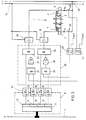
- the shown schematically Switch valve 1 controls the flow of a hydraulic Pressure medium.
- the switching valve 1 is with four useful connections P, A, B and T.
- the pump connection is in the usual way marked with P and the tank connection with T. Die Connections for a hydraulic consumer are marked with A and B designated.
- the reference number 2 is only symbolic shown control piston of the switching valve 1. He is held in its central position by two springs 3 and 4. This position is the rest position of the switching valve 1, the ports P, A, B and T are blocked in it.
- Reference numerals 5 and 6 denote two magnetic coils.
- the Armature of the magnetic coils 5, not shown in the drawing and 6 are operatively connected to the control piston 2.
- the control piston 2 Flows Via the solenoid 5 current, the control piston 2 is in the first of two working positions deflected. In this Working position, pressure medium flows from port P to Port A and from port B to port T. Current flows Via the solenoid 6, the control piston 2 is in the other Working position deflected. In this working position flows Pressure medium from port P to port B and from Port A to port T.
- the switching valve 1 is controlled via a bus system called AS-Interface with standardized interfaces.
- a subscriber in the form of a signal processing circuit 8 is connected to a digital data bus 7 with serial data transmission.
- the signal processing circuit 8 contains a coupling circuit 9 as well as four memory cells 10, 11, 12, 13 and four optocouplers 14, 15, 16, 17 connected to them.
- the coupling circuit 9 forms the interface to the data bus 7.
- the optocouplers 14, 15, 16, 17 provide for a galvanic separation between the signal processing circuit 8 and a logic circuit 20 connected downstream of it.
- Data telegrams with a serial bit sequence are transmitted on the data bus 7, which contain five address bits for the address of a subscriber and four useful data bits intended for the addressed subscriber.
- a data telegram contains further bits that identify the start and end of a data telegram.
- the coupling circuit 9 evaluates the data telegrams that are transmitted on the data bus 7. If the address data of the data telegram match the address of the signal processing circuit 8, the four useful data bits contained in the data telegram are stored in the memory cells 10, 11, 12 and 13. For the duration of a bus cycle, the user data bits are available in parallel form for further processing. Binary data are stored in the memory cells 10 to 13, each only the value 0 "or the value 1 "can accept.
- the logic circuit 20 links the output signals the optocouplers 14 to 17 to control signals for the Solenoid coils 5 and 6 of the switching valve 1.
- the logic circuit 20 contains two pulse width modulators 21 and 22, four AND gates 23, 24, 25, 25 and two NOT gates 27 and 28.
- the output of optocoupler 14 is directly connected to the an input of the AND gate 25 connected.
- the other entrance of the AND gate 25 is via the NOT gate 27 with the output of the AND gate 23 connected.
- the inputs of the AND gate 23 are the output signal of the optocoupler 15 and the output signal of the pulse width modulator 21 supplied.
- the output of the optocoupler 16 is directly connected to the connected to an input of the AND gate 26.
- the other entrance of the AND gate 26 is via the NOT gate 28 with the output of the AND gate 24 connected.
- the inputs of the AND gate 24 are the output signal of the optocoupler 17 and the output signal of the pulse width modulator 22 supplied.
- the output signal of the AND gate 25 is fed to the control input of a first switching amplifier 30.
- the output signal of the AND gate 25 is the same 1 ", an electrical current flows from a first electrical line 31 (with a voltage of, for example, +24 V) via the switching amplifier 30 and the magnetic coil 6 to a second electrical line 32, which is connected to ground potential.
- the one flowing via the magnetic coil 6 Current is designated i 6.
- the output signal of the AND gate 25 is the same 0 "is the
- the output signal of the AND gate 26 is fed to the control input of a second switching amplifier 33.
- the output signal of the AND gate 26 is the same 1 ", an electrical current flows from the electrical line 31 via the switching amplifier 33 and the magnet coil 5 to the electrical line 32 connected to ground potential.
- the current flowing via the magnet coil 5 is denoted by i 5.
- Is the output signal of the AND gate 25 equal 0 ", the current flow from line 31 via solenoid 5 to line 32 is interrupted.
- the one input of the AND gate 25 from the optocoupler 14 is the value 0 ".
- the output of the AND gate 25 is therefore also independent of the value of the output signal of the NOT gate 27
- the current flow from line 31 via magnetic coil 6 to line 32 is interrupted in this case.
- the value of the input of AND gate 26 connected to optocoupler 16 is also the value 0 ".
- the output of the AND gate 26 is therefore also independent of the value of the output signal of the NOT gate 28 0 ".
- the current flow from the line 31 via the solenoid 5 to the line 32 is interrupted in this case.
- the value is in the memory cell 10 1 "and in memory cells 11, 12 and 13 the value continues 0 "stored, the output signal of the AND gate 26 does not change. It retains the value 0 "because the value stored in the memory cell 12 has not changed. Since the output signal of the optocoupler 14 is now the same 1 ", the output signal of the AND gate 25 is equal to the output signal of the NOT gate 27.
- the value of the input of the AND gate 23 connected to the output of the optocoupler 15 is the value 0 ". This means that the output signal of the AND gate 23 is the same regardless of the output signal of the pulse width modulator 21 0 ". The output signal of the NOT gate 27 is thus the same 1 ".
- the switching amplifier 33 Since both input signals of the AND gate 25 have the value 1 ", the switching amplifier 33 will also have the value 1 ", and the switching amplifier 33 closes the circuit from the line 31 via the solenoid 6 to the line 32.
- the current i 6 flowing through the solenoid 6 results from the amount of voltage between the lines 31 and 32 divided by the ohmic Resistance of the magnetic coil 6. This current is referred to below as i 6max .
- the output signal of the AND gate 26 does not change. It retains the value 0 "at. Since the output signal of the optocoupler 14 remains the same 1 ", the output signal of the AND gate 25 is equal to the output signal of the NOT gate 27. Since the output signal of the optocoupler 15 is now also the same 1 ", the output signal of the AND gate 23 is determined by the output signal of the pulse width modulator 21. The output signal of the NOT gate 27 is always the same 0 "if both input signals of the AND gate 23 are the same 1 ".
- the input signal of the switching amplifier 30 is always the same 0 "is when the output signal of the pulse width modulator 21 is the same 1 ". So that a current flows through the magnet coil 6, the mean value of which is, for example, equal to 70% of i 6max , the pulse duty factor of the pulse width modulator 21 is set such that its output signal is equal to a period for 70% 0 "and the same in the remaining 30% of the period Is 1 ".
- the part of the connected to the optocouplers 16 and 17 Linking circuit 20 is like that to the optocoupler 14 and 15 connected part of the logic circuit 20 built up.
- the linking of the in the memory cells 12 and 13 stored values is done in the same way as the Linking of the memory cells 10 described above and 11 stored values.
- the value is in the memory cell 10 0 "is stored, the output signal of the AND gate 25 is the same regardless of the value stored in the memory cell 11 0 ".
- the value is also in the memory cell 12 1 ", the output signal of the AND gate 26 is determined by the output signal of the NOT gate 28, since the AND gate 26 from the optocoupler 16 has the value 1 "is supplied.
- the output signal of the AND gate 26 is the same 1 "if the value in the memory cell 13 0 "is stored.
- the switching amplifier 33 has the value 1 "is supplied, it closes the circuit from line 31 via solenoid 5 to line 32. Current i 5 flowing through solenoid 5 results from the amount of voltage between lines 31 and 32 divided by the ohmic resistance of Magnetic coil 5.
- i 5max is the value both in the memory cell 12 and in the memory cell 13 1 "
- the output signal of the AND gate 26 is determined by the output signal of the pulse width modulator 22.
- the output signal of the AND gate 26 is the same 0 "when the output signal of the pulse width modulator 22 is the same 1 ".
- the output signal of the AND gate 26 is the same 1 "when the output signal of the pulse width modulator 22 is the same So that a current flows through the magnet coil 5, the mean time value of which is, for example, equal to 70% of i 5max , the pulse duty factor of the pulse width modulator 22 is set such that its output signal equals a period for 70% 0 "and the same in the remaining 30% of the period Is 1 ".
- the value is in the memory cell 10 1 "and the value in the memory cell 11 0 "stored, the current i 6max flows through the magnetic coil 6 in the steady state.
- This current is selected to be at least as large as the pull-in current of the magnetic coil 6. It is in addition to the value 1 "in the memory cell 10 also in the memory cell 11 the value 1 "stored, only a current reduced according to the holding current flows through the magnetic coil 6, the mean time value of which in this example is 0.7 ⁇ i 6max .
- the value is in the memory cell 12 1 "and in the memory cell 13 the value 0 "stored, the current i 5max flows through the solenoid 5 in the steady state. This current is selected to be at least as large as the starting current of the solenoid 5. It is in addition to the value 1 "in the memory cell 12 also in the memory cell 13 the value 1 "stored, only a current reduced in accordance with the holding current flows through the magnetic coil 6, the mean time value in this example being 0.7 ⁇ i 5max .
- the duty cycle must the pulse width modulators 21 and 22 are set in this way be that even at the smallest allowable voltage between the lines 31 and 32 for holding the armature at least the required holding current still flows.
- FIG. 2 shows a control circuit for an electromagnetic actuated hydraulic switching valve, at the instead of pulse width modulators with fixed Duty cycle, a current control for the holding current is provided is.
- a current control for the holding current is provided is.
- a current measuring device 40 and a comparator 41 are provided.
- a current measuring device 42 and a comparator 43 instead of the pulse width modulator 22 a current measuring device 42 and a comparator 43 provided.
- the comparator 41 compares the instantaneous value of the current flowing through the magnetic coil 6 with a reference value I ref6 . If the current i 6 is greater than the reference value I ref6 , the output signal of the comparator 41 takes the value 1 ". The value is switched amplifier 30 0 "until the current i 6 has become smaller than the reference value I ref6 . If the current i 6 is smaller than the reference value I ref6 , the output signal of the comparator 41 takes the value 0 "on. The switching amplifier 30 now becomes the value 1 "until the current i 6 has become greater than the reference value I ref6 .
- the output signal of the comparator 41 determines the output signal of the AND gate 25 and thus the activation of the switching amplifier 30.
- the time average of the current flowing through the solenoid coil 6 is such that it is equal to the reference value I ref6 .
- the comparator 43 compares the instantaneous value of the current flowing through the magnet coil 5 with a reference value I ref5 . If the current i 5 is greater than the reference value I ref5 , the output signal of the comparator 43 takes the value 1 ". The value is switched amplifier 33 0 "until the current i 5 has become smaller than the reference value I ref5 . If the current i 5 is smaller than the reference value I ref5 , the output signal of the comparator 43 takes the value 0 ". The switching amplifier 33 now becomes the value 1 "until the current i 5 has become greater than the reference value I ref5 .
- the output signal of the comparator 43 determines the output signal of the AND gate 25 and thus the activation of the switching amplifier 33.
- the time average of the current flowing through the solenoid coil 5 is such that it is equal to the reference value I ref5 .
- the electrical isolation by the optocouplers 14 to 17 allows the signal processing circuit 8 from the To supply data bus 7 while the logic circuit 20 supplied from the voltage between lines 31 and 32 becomes.
Landscapes
- Engineering & Computer Science (AREA)
- Physics & Mathematics (AREA)
- Fluid Mechanics (AREA)
- Mechanical Engineering (AREA)
- General Engineering & Computer Science (AREA)
- Chemical & Material Sciences (AREA)
- Analytical Chemistry (AREA)
- Electromagnetism (AREA)
- Computer Networks & Wireless Communication (AREA)
- Signal Processing (AREA)
- Magnetically Actuated Valves (AREA)
- Massaging Devices (AREA)
Applications Claiming Priority (2)
| Application Number | Priority Date | Filing Date | Title |
|---|---|---|---|
| DE19853739A DE19853739A1 (de) | 1998-11-21 | 1998-11-21 | Verfahren zur Ansteuerung von elektrisch betätigten Schaltventilen |
| DE19853739 | 1998-11-21 |
Publications (3)
| Publication Number | Publication Date |
|---|---|
| EP1002961A2 true EP1002961A2 (fr) | 2000-05-24 |
| EP1002961A3 EP1002961A3 (fr) | 2002-05-15 |
| EP1002961B1 EP1002961B1 (fr) | 2004-01-14 |
Family
ID=7888545
Family Applications (1)
| Application Number | Title | Priority Date | Filing Date |
|---|---|---|---|
| EP99122530A Expired - Lifetime EP1002961B1 (fr) | 1998-11-21 | 1999-11-12 | Procédé pour la commande de soupapes de commutation à actionnement électrique |
Country Status (3)
| Country | Link |
|---|---|
| EP (1) | EP1002961B1 (fr) |
| AT (1) | ATE257914T1 (fr) |
| DE (2) | DE19853739A1 (fr) |
Cited By (3)
| Publication number | Priority date | Publication date | Assignee | Title |
|---|---|---|---|---|
| EP1528695A3 (fr) * | 2003-10-31 | 2005-12-21 | Norgren GmbH | Dispositif de commande électrique |
| WO2006008509A1 (fr) * | 2004-07-16 | 2006-01-26 | Norgren Limited | Soupapes de regulation de debit de fluide |
| WO2006108403A1 (fr) * | 2005-04-11 | 2006-10-19 | Norgren Gmbh | Dispositif de couplage electro-optique |
Families Citing this family (2)
| Publication number | Priority date | Publication date | Assignee | Title |
|---|---|---|---|---|
| DE10206657B4 (de) * | 2002-02-15 | 2006-06-08 | Schiff, Andreas, Dr. | Aktuator-Sensor-Interface für die Automation mit erweiterter Funktion |
| DE102004029549A1 (de) † | 2004-06-18 | 2006-01-05 | Bosch Rexroth Aktiengesellschaft | Busmodul |
Family Cites Families (10)
| Publication number | Priority date | Publication date | Assignee | Title |
|---|---|---|---|---|
| DE3802254A1 (de) * | 1988-01-27 | 1989-08-24 | Kloeckner Ferromatik Desma | Verfahren zum steuern bzw. regeln von spritzgiessmaschinen |
| DE3819761A1 (de) * | 1988-06-10 | 1989-12-14 | Vib Apparatebau Gmbh | Digitalventilsystem |
| DE9219093U1 (de) * | 1992-09-22 | 1997-10-16 | Mannesmann AG, 40213 Düsseldorf | Ansteuereinrichtung für Ventile und/oder Ventileinheiten |
| ES2076087B1 (es) * | 1993-06-18 | 1996-06-01 | Avacon Sa | Secuenciador programable mejorado para las electrovalvulas utilizadas en una instalacion de fabricacion de vidrio hueco. |
| US5329965A (en) * | 1993-07-30 | 1994-07-19 | The Perkin-Elmer Corporation | Hybrid valving system for varying fluid flow rate |
| DE4437774A1 (de) * | 1994-10-24 | 1996-04-25 | Edag Eng & Design Ag | Verfahren zum Versorgen zumindest zweier elektrischer Verbraucher und nach dem Verfahren arbeitender Hubzylinder |
| DE4444024A1 (de) * | 1994-12-10 | 1996-06-13 | Festo Kg | Steuereinrichtung, insbesondere zur Ansteuerung von Ventilen |
| DE29600866U1 (de) * | 1996-01-19 | 1996-03-07 | Festo Kg, 73734 Esslingen | Schaltungsanordnung zur Steuerung von Magnetventilen |
| DE19606673C1 (de) * | 1996-02-22 | 1997-04-10 | Siemens Ag | Aktuator-Sensor-Interface-System |
| DE19742038A1 (de) * | 1997-09-24 | 1999-03-25 | Wabco Gmbh | Verfahren zur Zustandserkennung bei einem Magnetventil |
-
1998
- 1998-11-21 DE DE19853739A patent/DE19853739A1/de not_active Withdrawn
-
1999
- 1999-11-12 DE DE59908298T patent/DE59908298D1/de not_active Expired - Fee Related
- 1999-11-12 EP EP99122530A patent/EP1002961B1/fr not_active Expired - Lifetime
- 1999-11-12 AT AT99122530T patent/ATE257914T1/de not_active IP Right Cessation
Non-Patent Citations (1)
| Title |
|---|
| None |
Cited By (4)
| Publication number | Priority date | Publication date | Assignee | Title |
|---|---|---|---|---|
| EP1528695A3 (fr) * | 2003-10-31 | 2005-12-21 | Norgren GmbH | Dispositif de commande électrique |
| WO2006008509A1 (fr) * | 2004-07-16 | 2006-01-26 | Norgren Limited | Soupapes de regulation de debit de fluide |
| WO2006108403A1 (fr) * | 2005-04-11 | 2006-10-19 | Norgren Gmbh | Dispositif de couplage electro-optique |
| CN101156336B (zh) * | 2005-04-11 | 2013-03-20 | 诺格伦有限责任公司 | 电光耦合装置 |
Also Published As
| Publication number | Publication date |
|---|---|
| DE59908298D1 (de) | 2004-02-19 |
| EP1002961A3 (fr) | 2002-05-15 |
| ATE257914T1 (de) | 2004-01-15 |
| DE19853739A1 (de) | 2000-05-25 |
| EP1002961B1 (fr) | 2004-01-14 |
Similar Documents
| Publication | Publication Date | Title |
|---|---|---|
| DE10016712C5 (de) | Sicherheitsschaltgerät und Verfahren zur Einstellung einer Betriebsart eines Sicherheitsschaltgeräts | |
| EP0393233B1 (fr) | Système de transmission de signaux | |
| DE10234091A1 (de) | Verfahren zur Überwachung von wenigstens zwei elektromagnetischen Ventilen einer Brennkraftmaschine, insbesondere eines Kraftfahrzeugs | |
| DE102016213725B4 (de) | Reihenmodul, Verbindungsmodul und modular ausgebildete Steuerungsanordnung | |
| EP1002961B1 (fr) | Procédé pour la commande de soupapes de commutation à actionnement électrique | |
| DE10315282A1 (de) | Schaltungsanordnung und Verfahren zur Ansteuerung eines bistabilen Magnetventils | |
| EP1287900B1 (fr) | Installation de revêtement comprenant une boucle de régulation | |
| DE4332995C1 (de) | Verfahren zur Ansteuerung von parallel angeordneten Relais | |
| DE3787132T2 (de) | Steuer- und Kontrollvorrichtung für Schütze und entsprechendes Kontrollverfahren. | |
| EP1761710B1 (fr) | Module bus permettant de commander des valves fluidiques | |
| EP0019890B1 (fr) | Circuit d'excitation d'électro-aimants dans des appareils d'enregistrement utilisés dans la technique du téléscripteur | |
| DE102019203574B4 (de) | Ventilanordnung und Verfahren | |
| EP1528695A2 (fr) | Dispositif de commande électrique | |
| DE19726225B4 (de) | Anordnung mit einem oder mehreren hydraulischen Stellgliedern | |
| DE102009014620A1 (de) | Adressabhängige Sicherheitscodefolgen für sichere Eingangsslaves bei AS-Interface | |
| DE102017011453B4 (de) | Elektromagnetische Vorrichtung zur gesteuerten Krafterzeugung und Verfahren zum Betrieb der Vorrichtung | |
| EP1770456B1 (fr) | Unité périphérique pour un système automatisé | |
| EP0822471B1 (fr) | Dispositif électronique | |
| DE2723646A1 (de) | Einrichtung zur steuerung der erregung einer gleichstrommaschine | |
| DE1128888B (de) | Torschaltung zum Steuern der Impedanz, die einer Antriebsstromquelle dargeboten wird | |
| DE3535844C2 (de) | Schaltungsanordnung zur elektrischen Ansteuerung eines Verbrauchers | |
| DE102022113397A1 (de) | Steuerung eines Volumenstroms eines Fluids mittels einer Ventilanordnung | |
| DE102016204461A1 (de) | Regelung einer induktiven Last mittels eines unstetigen Reglers mit einer stochastisch veränderten Schaltschwelle | |
| EP0037853A2 (fr) | Circuit électronique pour engendrer une valeur de référence pour systèmes de freinage électro-pneumatiques de véhicules ferroviaires | |
| DE102022121986A1 (de) | Ventilanordnung |
Legal Events
| Date | Code | Title | Description |
|---|---|---|---|
| PUAI | Public reference made under article 153(3) epc to a published international application that has entered the european phase |
Free format text: ORIGINAL CODE: 0009012 |
|
| AK | Designated contracting states |
Kind code of ref document: A2 Designated state(s): AT BE CH CY DE DK ES FI FR GB GR IE IT LI LU MC NL PT SE |
|
| AX | Request for extension of the european patent |
Free format text: AL;LT;LV;MK;RO;SI |
|
| PUAL | Search report despatched |
Free format text: ORIGINAL CODE: 0009013 |
|
| AK | Designated contracting states |
Kind code of ref document: A3 Designated state(s): AT BE CH CY DE DK ES FI FR GB GR IE IT LI LU MC NL PT SE |
|
| AX | Request for extension of the european patent |
Free format text: AL;LT;LV;MK;RO;SI |
|
| RAP1 | Party data changed (applicant data changed or rights of an application transferred) |
Owner name: BOSCH REXROTH AG |
|
| 17P | Request for examination filed |
Effective date: 20021024 |
|
| AKX | Designation fees paid |
Designated state(s): AT BE CH CY DE DK ES FI FR GB GR IE IT LI LU MC NL PT SE |
|
| GRAH | Despatch of communication of intention to grant a patent |
Free format text: ORIGINAL CODE: EPIDOS IGRA |
|
| RBV | Designated contracting states (corrected) |
Designated state(s): DE FI FR GB IT SE |
|
| RBV | Designated contracting states (corrected) |
Designated state(s): AT DE FI FR GB IT SE |
|
| GRAS | Grant fee paid |
Free format text: ORIGINAL CODE: EPIDOSNIGR3 |
|
| GRAA | (expected) grant |
Free format text: ORIGINAL CODE: 0009210 |
|
| AK | Designated contracting states |
Kind code of ref document: B1 Designated state(s): AT DE FI FR GB IT SE |
|
| PG25 | Lapsed in a contracting state [announced via postgrant information from national office to epo] |
Ref country code: IT Free format text: LAPSE BECAUSE OF FAILURE TO SUBMIT A TRANSLATION OF THE DESCRIPTION OR TO PAY THE FEE WITHIN THE PRE;WARNING: LAPSES OF ITALIAN PATENTS WITH EFFECTIVE DATE BEFORE 2007 MAY HAVE OCCURRED AT ANY TIME BEFORE 2007. THE CORRECT EFFECTIVE DATE MAY BE DIFFERENT FROM THE ONE RECORDED.SCRIBED TIME-LIMIT Effective date: 20040114 Ref country code: GB Free format text: LAPSE BECAUSE OF FAILURE TO SUBMIT A TRANSLATION OF THE DESCRIPTION OR TO PAY THE FEE WITHIN THE PRESCRIBED TIME-LIMIT Effective date: 20040114 Ref country code: FR Free format text: LAPSE BECAUSE OF FAILURE TO SUBMIT A TRANSLATION OF THE DESCRIPTION OR TO PAY THE FEE WITHIN THE PRESCRIBED TIME-LIMIT Effective date: 20040114 Ref country code: FI Free format text: LAPSE BECAUSE OF FAILURE TO SUBMIT A TRANSLATION OF THE DESCRIPTION OR TO PAY THE FEE WITHIN THE PRESCRIBED TIME-LIMIT Effective date: 20040114 |
|
| REG | Reference to a national code |
Ref country code: GB Ref legal event code: FG4D Free format text: NOT ENGLISH |
|
| REG | Reference to a national code |
Ref country code: IE Ref legal event code: FG4D Free format text: GERMAN |
|
| REF | Corresponds to: |
Ref document number: 59908298 Country of ref document: DE Date of ref document: 20040219 Kind code of ref document: P |
|
| PG25 | Lapsed in a contracting state [announced via postgrant information from national office to epo] |
Ref country code: SE Free format text: LAPSE BECAUSE OF FAILURE TO SUBMIT A TRANSLATION OF THE DESCRIPTION OR TO PAY THE FEE WITHIN THE PRESCRIBED TIME-LIMIT Effective date: 20040414 |
|
| GBV | Gb: ep patent (uk) treated as always having been void in accordance with gb section 77(7)/1977 [no translation filed] |
Effective date: 20040114 |
|
| REG | Reference to a national code |
Ref country code: IE Ref legal event code: FD4D |
|
| PG25 | Lapsed in a contracting state [announced via postgrant information from national office to epo] |
Ref country code: AT Free format text: LAPSE BECAUSE OF NON-PAYMENT OF DUE FEES Effective date: 20041112 |
|
| PLBE | No opposition filed within time limit |
Free format text: ORIGINAL CODE: 0009261 |
|
| STAA | Information on the status of an ep patent application or granted ep patent |
Free format text: STATUS: NO OPPOSITION FILED WITHIN TIME LIMIT |
|
| 26N | No opposition filed |
Effective date: 20041015 |
|
| EN | Fr: translation not filed | ||
| PG25 | Lapsed in a contracting state [announced via postgrant information from national office to epo] |
Ref country code: DE Free format text: LAPSE BECAUSE OF NON-PAYMENT OF DUE FEES Effective date: 20050601 |