EP1002993B1 - Kessel für flüssige Brennstoffe - Google Patents
Kessel für flüssige Brennstoffe Download PDFInfo
- Publication number
- EP1002993B1 EP1002993B1 EP19990890351 EP99890351A EP1002993B1 EP 1002993 B1 EP1002993 B1 EP 1002993B1 EP 19990890351 EP19990890351 EP 19990890351 EP 99890351 A EP99890351 A EP 99890351A EP 1002993 B1 EP1002993 B1 EP 1002993B1
- Authority
- EP
- European Patent Office
- Prior art keywords
- heating surface
- boiler
- heating
- boiler according
- flame generator
- Prior art date
- Legal status (The legal status is an assumption and is not a legal conclusion. Google has not performed a legal analysis and makes no representation as to the accuracy of the status listed.)
- Expired - Lifetime
Links
- 239000000446 fuel Substances 0.000 title claims description 12
- 239000007788 liquid Substances 0.000 title claims description 4
- 238000010438 heat treatment Methods 0.000 claims description 87
- 239000003546 flue gas Substances 0.000 claims description 18
- UGFAIRIUMAVXCW-UHFFFAOYSA-N Carbon monoxide Chemical compound [O+]#[C-] UGFAIRIUMAVXCW-UHFFFAOYSA-N 0.000 claims description 12
- 238000002485 combustion reaction Methods 0.000 claims description 12
- 239000000203 mixture Substances 0.000 claims description 8
- XLYOFNOQVPJJNP-UHFFFAOYSA-N water Substances O XLYOFNOQVPJJNP-UHFFFAOYSA-N 0.000 claims description 8
- 238000001704 evaporation Methods 0.000 claims description 5
- 238000009833 condensation Methods 0.000 description 7
- 230000005494 condensation Effects 0.000 description 7
- MWUXSHHQAYIFBG-UHFFFAOYSA-N Nitric oxide Chemical compound O=[N] MWUXSHHQAYIFBG-UHFFFAOYSA-N 0.000 description 6
- 238000009434 installation Methods 0.000 description 4
- 238000012423 maintenance Methods 0.000 description 4
- 230000015572 biosynthetic process Effects 0.000 description 3
- 239000007789 gas Substances 0.000 description 3
- 230000005855 radiation Effects 0.000 description 3
- 241001156002 Anthonomus pomorum Species 0.000 description 2
- 238000000889 atomisation Methods 0.000 description 2
- 230000008020 evaporation Effects 0.000 description 2
- 230000002349 favourable effect Effects 0.000 description 2
- 238000003303 reheating Methods 0.000 description 2
- 229910000831 Steel Inorganic materials 0.000 description 1
- 230000001133 acceleration Effects 0.000 description 1
- 238000010276 construction Methods 0.000 description 1
- 230000007797 corrosion Effects 0.000 description 1
- 238000005260 corrosion Methods 0.000 description 1
- 239000003779 heat-resistant material Substances 0.000 description 1
- 230000002631 hypothermal effect Effects 0.000 description 1
- 230000000977 initiatory effect Effects 0.000 description 1
- 238000007689 inspection Methods 0.000 description 1
- 239000011810 insulating material Substances 0.000 description 1
- 238000009413 insulation Methods 0.000 description 1
- 238000004519 manufacturing process Methods 0.000 description 1
- 239000000463 material Substances 0.000 description 1
- 239000002184 metal Substances 0.000 description 1
- 230000001105 regulatory effect Effects 0.000 description 1
- 239000007787 solid Substances 0.000 description 1
- 239000010959 steel Substances 0.000 description 1
Images




Classifications
-
- F—MECHANICAL ENGINEERING; LIGHTING; HEATING; WEAPONS; BLASTING
- F23—COMBUSTION APPARATUS; COMBUSTION PROCESSES
- F23C—METHODS OR APPARATUS FOR COMBUSTION USING FLUID FUEL OR SOLID FUEL SUSPENDED IN A CARRIER GAS OR AIR
- F23C5/00—Disposition of burners with respect to the combustion chamber or to one another; Mounting of burners in combustion apparatus
- F23C5/02—Structural details of mounting
-
- F—MECHANICAL ENGINEERING; LIGHTING; HEATING; WEAPONS; BLASTING
- F23—COMBUSTION APPARATUS; COMBUSTION PROCESSES
- F23D—BURNERS
- F23D11/00—Burners using a direct spraying action of liquid droplets or vaporised liquid into the combustion space
- F23D11/04—Burners using a direct spraying action of liquid droplets or vaporised liquid into the combustion space the spraying action being obtained by centrifugal action
- F23D11/08—Burners using a direct spraying action of liquid droplets or vaporised liquid into the combustion space the spraying action being obtained by centrifugal action using a vertical shaft
-
- F—MECHANICAL ENGINEERING; LIGHTING; HEATING; WEAPONS; BLASTING
- F23—COMBUSTION APPARATUS; COMBUSTION PROCESSES
- F23M—CASINGS, LININGS, WALLS OR DOORS SPECIALLY ADAPTED FOR COMBUSTION CHAMBERS, e.g. FIREBRIDGES; DEVICES FOR DEFLECTING AIR, FLAMES OR COMBUSTION PRODUCTS IN COMBUSTION CHAMBERS; SAFETY ARRANGEMENTS SPECIALLY ADAPTED FOR COMBUSTION APPARATUS; DETAILS OF COMBUSTION CHAMBERS, NOT OTHERWISE PROVIDED FOR
- F23M9/00—Baffles or deflectors for air or combustion products; Flame shields
- F23M9/06—Baffles or deflectors for air or combustion products; Flame shields in fire-boxes
-
- F—MECHANICAL ENGINEERING; LIGHTING; HEATING; WEAPONS; BLASTING
- F24—HEATING; RANGES; VENTILATING
- F24H—FLUID HEATERS, e.g. WATER OR AIR HEATERS, HAVING HEAT-GENERATING MEANS, e.g. HEAT PUMPS, IN GENERAL
- F24H1/00—Water heaters, e.g. boilers, continuous-flow heaters or water-storage heaters
- F24H1/22—Water heaters other than continuous-flow or water-storage heaters, e.g. water heaters for central heating
- F24H1/24—Water heaters other than continuous-flow or water-storage heaters, e.g. water heaters for central heating with water mantle surrounding the combustion chamber or chambers
- F24H1/26—Water heaters other than continuous-flow or water-storage heaters, e.g. water heaters for central heating with water mantle surrounding the combustion chamber or chambers the water mantle forming an integral body
- F24H1/28—Water heaters other than continuous-flow or water-storage heaters, e.g. water heaters for central heating with water mantle surrounding the combustion chamber or chambers the water mantle forming an integral body including one or more furnace or fire tubes
- F24H1/282—Water heaters other than continuous-flow or water-storage heaters, e.g. water heaters for central heating with water mantle surrounding the combustion chamber or chambers the water mantle forming an integral body including one or more furnace or fire tubes with flue gas passages built-up by coaxial water mantles
-
- F—MECHANICAL ENGINEERING; LIGHTING; HEATING; WEAPONS; BLASTING
- F24—HEATING; RANGES; VENTILATING
- F24H—FLUID HEATERS, e.g. WATER OR AIR HEATERS, HAVING HEAT-GENERATING MEANS, e.g. HEAT PUMPS, IN GENERAL
- F24H1/00—Water heaters, e.g. boilers, continuous-flow heaters or water-storage heaters
- F24H1/48—Water heaters for central heating incorporating heaters for domestic water
- F24H1/50—Water heaters for central heating incorporating heaters for domestic water incorporating domestic water tanks
Definitions
- the present invention relates to a boiler for liquid fuels with a Burner, heating surfaces and a flue gas outlet according to the Claim 1.
- Boilers are known in which vertically arranged cylindrical heating surfaces are provided. Such boilers are operated with evaporator burners, which are arranged below the heating surfaces in their own combustion chamber are. The combustion air is introduced by a fan provided for this purpose. Between the combustion chamber and the one enclosed by the heating surfaces An annular guide member is arranged in space. With such a The heat is transferred from the flames or flue gas to the boiler Heating surfaces primarily by gas radiation and is therefore of moderate efficiency. Furthermore, with such boilers, at least at certain operating points Form areas in which there is no flow, so that the Heat transfer on the heating surfaces is further deteriorated.
- boilers are known in which fuels before ignition and before actual start of combustion within a hollow body, a so-called Flame generator, mixed in gaseous state with combustion air are and exit through openings in this flame generator to be ignited and get burned.
- DE 42 25 749 A relates to an evaporation burner. With this burner fuel is vaporized in a porous body and into a cylindrical one Mixing tube introduced. The mixing with the combustion air takes place in this mixing tube. A cylindrical body is concentric outside the mixing tube Redirection of the flames arranged. A boiler with heating surfaces or the like is in not described in this document.
- EP 0 233 330 A discloses a boiler with a pressure atomizing burner with a nozzle that creates flames in the combustion chamber.
- a flame producer that is, a component within which there is a combustible mixture, that burns outside of it is not disclosed in this document, i.e. that this boiler is fundamentally different in design from the object of the present invention.
- EP 0 347 797 A also relates to a pressure atomizing burner which is horizontal in a boiler is installed.
- EP 0 233 330 A it is noted that premix burners are usually only used for vertical installation work satisfactorily because of a homogeneous flame formation cannot be done with horizontal installation.
- the object of the present invention is the boiler described above to further develop that efficient heat transfer to the heating surfaces and thus high efficiency is achieved. Furthermore, the exhaust emissions, in particular nitrogen oxide emissions can be reduced. By achieving one high performance should allow a small installation space with high performance become. At the same time, maintenance and repair work should be easy and be possible without any problems.
- the particularly advantageous solution of the invention is mainly achieved by that the essential part of the burner, namely the flame generator is located within the space enclosed by the heating surface.
- the heat transfer can not only by convection and gas radiation but also done by solid state radiation, resulting in a significantly higher efficiency leads.
- the premix burner is located below the flame generator is arranged, and detachable with a part containing the heating surfaces of the boiler is connected.
- the boiler according to the invention easy to dismantle to carry out inspection and maintenance work, so that the maintenance effort can be reduced.
- the performance of the boiler according to the invention can thereby be improved be that a guide body is provided above the flame generator is formed essentially concentrically with the flame generator. By the narrowing of the cross section according to the guide body will accelerate the Flue gas flow reached, so that an improved heat transfer to the Heating surfaces can be reached.
- a particular improvement in the flue gas flow can be achieved that a deflecting body is provided above the first heating surface, and that a further heating surface is arranged radially outside the first heating surface is. In this way it is caused that the flue gases initially on the inside of the first heating surface flow up over the top of the first Heating surface are deflected and continue on the outside of this heating surface stream.
- the speed can be reduced by suitably designed flow baffles the flow can be adjusted so that an optimal heat transfer is possible.
- a heating return in the upper area of the first heating surface flows tangentially. It is particularly preferred if the Heating return a main inflow opening in the first heating surface and a secondary inflow opening in a further heating surface outside the first Heating surface is arranged.
- the heating return usually introduced in the lower part of the boiler.
- the Boilers of the construction according to the invention would, however, in certain Operating conditions lead to the formation of condensates. When initiating the Returning to the top of the boiler can cause condensation in all Operating conditions can be safely avoided.
- heating circuits are served by one boiler, for example a heating circuit for underfloor heating and another Heating circuit for radiators.
- Such heating circuits must be on a clearly different one Temperature level can be regulated independently of one another.
- a mutual one Influencing can largely be ruled out by the fact that preferably the heating return a first return and another Return, which before entering the heating surface in the first return is introduced like a nozzle.
- a further preferred embodiment variant of the invention provides that the first heating surface is designed as a cylindrical body on the outside is washed by boiler water, and that reheating surfaces are tubular above the first heating surface are arranged.
- Such a structure is particularly suitable for compact, wall-hung central heating boiler with or without an integrated Water heater. With such a solution, the vertical installation position in be advantageously used. Because such wall boilers primarily in the living area installed, come the special advantages of pre-evaporating Premix burner especially in terms of low noise emissions to carry.
- the boiler according to the invention consists of a frame 1 on which a premix burner is arranged, which consists of an evaporator unit 2 and one above arranged cylindrical flame generator 4 there.
- the evaporator unit 2 is via an air supply line 3 with combustion air and a Fuel line, not shown, supplied with a liquid fuel.
- a flange plate 6 is arranged in the upper section of the frame 1.
- a seal is designated 9.
- FIGS. 2 and 3 is a preferred embodiment of the releasable connection between the frame 1 and the upper part 5 of the boiler shown.
- the flange plate 6 attached in the manner of a bayonet lock on part 5 of the boiler become.
- a seal that is not visible in FIGS. 2 and 3 is in a groove in the lower one Section of part 5 inserted.
- a locking screw 10 serves to to generate the necessary contact pressure, and an unintentional loosening of the To prevent burner.
- a first heating surface 11 is provided, which is essentially is cylindrical and concentric with the flame generator 4th is arranged. Above the flame generator 4 is on the first heating surface 11 a guide body 12 is arranged, which is also cylindrical and arranged concentrically to the flame generator 4 and the first heating surface 11 is.
- the guide body 12 is made of a heat-resistant and insulating material manufactured.
- Radially outside and concentric to the first heating surface 11 is one further heating surface 13 arranged upwards through a deflecting body 14 is complete.
- Flow baffles 16 arranged on the outer circumference of the further heating surface 13, a flue gas vent 17 is attached.
- the structure described above achieves the following function.
- the end the evaporator unit 2 flowing fuel-air mixture is in the Flame generator 4 completely evaporated and released to the outside and burned.
- the flue gases initially flow along the arrow 18 along the Inner surface of the first heating surface 11 upwards.
- the deflecting body 14 deflects the flow towards the outside, so that this in the gap 15 between the first heating surface 11 and the other Heating surface 13 flows down.
- the upper deflector 14 is removable at the top of the other Heating surface 13 arranged.
- the baffles 16 force the flue gases to one up and down flow movement along the circumference of the heating surfaces 11, 13.
- the Boiler according to the present invention can be used both as a condensation boiler as well as a conventional low-temperature boiler.
- the heating surfaces in the flue gas path are dimensioned so generously and made of corrosion-resistant material, so that condensation of the flue gas can be brought about, whereby the heat of condensation of the in the exhaust gases contained water is exploited. This will make the Fuel contained energy used up to almost the calorific value.
- the emerging Condensate is discharged at the lowest point of the flue gas path 18. In such a case, the heating return is initiated at a low level Point of the heating surface. This ensures that the flue gases in the last part brought their flow path to the lowest possible temperature level so that a high degree of efficiency is achieved.
- the heating return has a first return connection 20 and another Return connection 21.
- These return connections 20, 21 are for example assigned to a floor heating circuit and a radiator heating circuit.
- the first Return is designed as a nozzle 22, around which an annular space 23 is concentric is arranged.
- the further return 21 opens into this annular space 23. In this way it is possible to use the circulation pumps for both heating circuits Arrange return, with a mutual influence of the two heating circuits is largely avoided.
- the united passes through a manifold 24 Return into a flow tube 25.
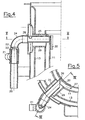
- the flow tube 25 opens in the first heating surface 11. From FIG. 5 it can be seen that the opening 26 of the Flow tube 25 is chamfered so that the backflow Heating medium has a tangential speed component along the Arrow 27 is granted.
- a boiler connector 29 envelops the flow tube 25. This configuration ensures that that the majority of the returned heating medium in the first heating surface 11 is introduced.
- a welded steel plate 33 in the area of The confluence of the flow tube 25 increases the thermal resistance and also prevents the occurrence of cold areas on the boiler wall, that could lead to condensation.
- Concentric a heating surface 11 is arranged for the flame generator 4.
- the heating surface 11 is closed at its top with a plate 31.
- reheating surfaces 32 are guided vertically upwards.
- flow obstacles bent in sheet metal used in a manner known per se, which extend the flow paths of the flue gases, to bring about an improved heat transfer.
- These missions are also referred to as turbolators 33.
- a Service water tank 34 arranged. All of these components are in common Tub 35 arranged, the intermediate space 36 with heating medium is filled. Insulation 37 prevents excessive heat loss.
- the evaporator unit 2 of the burner is arranged below the tub 35, and can, as in the embodiment described above, easily be expanded downwards.
- the combustion air is at 38 either supplied from the environment or from a corresponding pipeline.
- the Flue gas connection is designated 39.
- a premix burner is shown partially schematically in FIG. 7.
- a flame holder 4 On a Evaporator unit 2 is a flame holder 4, which has a variety of Has openings 40 in a network or grid-like structure.
- the interior 41 of the evaporator unit 2 is connected to the flame holder 4 via openings 42 in connection.
- Atomizer cup 45 On a shaft 43, which protrudes through an opening 44 into the interior 41, is a Atomizer cup 45 attached upwards through an atomizer plate 46 is covered. Atomizer blades 47, which also rotate with the shaft 43, cause a further swirling of the fuel, which is via a line 48 is introduced into the atomizer cup 45, and upwards from this exit.
- the combustion air is supplied by a fan, not shown, which can also be driven by the shaft 43 via the opening 44 in the Blown interior 41. This ensures that through the openings 42 a finely divided fuel-air mixture is guided.
- the burner according to the invention enables a very uniform temperature distribution be achieved so that high performance can be achieved and at the same time the nitrogen oxide emission can be reduced.
Landscapes
- Engineering & Computer Science (AREA)
- Chemical & Material Sciences (AREA)
- Combustion & Propulsion (AREA)
- Mechanical Engineering (AREA)
- General Engineering & Computer Science (AREA)
- Physics & Mathematics (AREA)
- Thermal Sciences (AREA)
- Combustion Of Fluid Fuel (AREA)
Priority Applications (2)
| Application Number | Priority Date | Filing Date | Title |
|---|---|---|---|
| AT99890351T ATE232948T1 (de) | 1998-11-12 | 1999-11-03 | Kessel für flüssige brennstoffe |
| SI9930265T SI1002993T1 (en) | 1998-11-12 | 1999-11-03 | Boiler for liquid fuels |
Applications Claiming Priority (2)
| Application Number | Priority Date | Filing Date | Title |
|---|---|---|---|
| AT189298A AT410588B (de) | 1998-11-12 | 1998-11-12 | Kessel für flüssige brennstoffe |
| AT189298 | 1998-11-12 |
Publications (3)
| Publication Number | Publication Date |
|---|---|
| EP1002993A2 EP1002993A2 (de) | 2000-05-24 |
| EP1002993A3 EP1002993A3 (de) | 2000-10-04 |
| EP1002993B1 true EP1002993B1 (de) | 2003-02-19 |
Family
ID=3523276
Family Applications (1)
| Application Number | Title | Priority Date | Filing Date |
|---|---|---|---|
| EP19990890351 Expired - Lifetime EP1002993B1 (de) | 1998-11-12 | 1999-11-03 | Kessel für flüssige Brennstoffe |
Country Status (4)
| Country | Link |
|---|---|
| EP (1) | EP1002993B1 (da) |
| AT (1) | AT410588B (da) |
| DE (1) | DE59904319D1 (da) |
| DK (1) | DK1002993T3 (da) |
Family Cites Families (7)
| Publication number | Priority date | Publication date | Assignee | Title |
|---|---|---|---|---|
| US4287857A (en) * | 1979-09-11 | 1981-09-08 | Leo Schnitzer | Burner-boiler combination and an improved burner construction therefor |
| JPS6199010A (ja) * | 1984-10-19 | 1986-05-17 | Matsushita Electric Ind Co Ltd | 液体燃料燃焼装置 |
| DE3608698A1 (de) * | 1986-01-18 | 1987-07-23 | Deutsche Forsch Luft Raumfahrt | Brenner-heizkessel-einheit |
| CH677139A5 (da) * | 1988-06-24 | 1991-04-15 | Ygnis Sa | |
| JP2520062B2 (ja) * | 1991-08-06 | 1996-07-31 | 株式会社ミクニ | 蒸発式バ―ナ |
| US5531212A (en) * | 1994-04-14 | 1996-07-02 | Clean Burn, Inc. | Multi oil furnace |
| DE19519963C2 (de) * | 1995-05-31 | 1997-07-17 | Pyropac Ag | Heizkessel |
-
1998
- 1998-11-12 AT AT189298A patent/AT410588B/de not_active IP Right Cessation
-
1999
- 1999-11-03 EP EP19990890351 patent/EP1002993B1/de not_active Expired - Lifetime
- 1999-11-03 DE DE59904319T patent/DE59904319D1/de not_active Expired - Fee Related
- 1999-11-03 DK DK99890351T patent/DK1002993T3/da active
Also Published As
| Publication number | Publication date |
|---|---|
| ATA189298A (de) | 2002-10-15 |
| DE59904319D1 (de) | 2003-03-27 |
| EP1002993A3 (de) | 2000-10-04 |
| EP1002993A2 (de) | 2000-05-24 |
| DK1002993T3 (da) | 2003-06-16 |
| AT410588B (de) | 2003-06-25 |
Similar Documents
| Publication | Publication Date | Title |
|---|---|---|
| DE69606189T2 (de) | Gasgerät zum erhitzen von flüssigkeiten | |
| EP0970327A1 (de) | Mit einem brenner ausgerüsteter heizkessel | |
| EP0394911B1 (de) | Feuerungsanlage | |
| DE102006000174B4 (de) | Öl-Vormischbrenner und Betriebsverfahren dafür | |
| EP0843083B1 (de) | Brennstoffvorverdampfer | |
| EP0348646B1 (de) | Brenner | |
| DE4417417A1 (de) | Brenneranordnung | |
| EP1002993B1 (de) | Kessel für flüssige Brennstoffe | |
| AT406507B (de) | Brenner mit separater zufuhr von brennstoff | |
| EP0132831B1 (de) | Gasbrenner, insbesondere für Flüssiggas, zum Einbau in einen Wärmetauscher | |
| EP2679897A1 (de) | Ölvormischbrenner mit Drallerzeugungsvorrichtung | |
| DE19534319C2 (de) | Einsatz für eine Kesselanlage, Kesselanlage und Verfahren zum Betreiben der Kesselanlage | |
| EP0209703B1 (de) | Glüheinsatz für Öfen, insbesondere Heizungskessel, sowie Ofen mit einem derartigen Glüheinsatz | |
| EP0867658B1 (de) | Verfahren und Vorrichtung zur Verbrennung von flüssigem Brennstoff | |
| DE69407128T2 (de) | Brennwertkessel in Modulbauweise für Heizungsanlagen | |
| DE3503553C2 (da) | ||
| AT323947B (de) | Feuebrohrkessel | |
| EP0190659A2 (de) | Heizungskessel | |
| DE4329195A1 (de) | Gasheizgerät und Verfahren zu seinem Betrieb | |
| CH684959A5 (de) | Verfahren für eine schadstoffarme Verbrennung in einem Kraftwerkskessel. | |
| AT406795B (de) | Brenner für gas- und ölheizungskessel | |
| DE4412365A1 (de) | Brenner für flüssigen Brennstoff, insbesondere Öl | |
| DE102009060882A1 (de) | Brennersystem | |
| DE8517157U1 (de) | Ofen, insbesondere Heizungskessel | |
| DE29514853U1 (de) | Einsatz für eine Kesselanlage und Kesselanlage |
Legal Events
| Date | Code | Title | Description |
|---|---|---|---|
| PUAI | Public reference made under article 153(3) epc to a published international application that has entered the european phase |
Free format text: ORIGINAL CODE: 0009012 |
|
| AK | Designated contracting states |
Kind code of ref document: A2 Designated state(s): AT BE CH CY DE DK ES FI FR GB GR IE IT LI LU MC NL PT SE |
|
| AX | Request for extension of the european patent |
Free format text: AL;LT;LV;MK;RO;SI |
|
| PUAL | Search report despatched |
Free format text: ORIGINAL CODE: 0009013 |
|
| AK | Designated contracting states |
Kind code of ref document: A3 Designated state(s): AT BE CH CY DE DK ES FI FR GB GR IE IT LI LU MC NL PT SE |
|
| AX | Request for extension of the european patent |
Free format text: AL;LT;LV;MK;RO;SI |
|
| 17P | Request for examination filed |
Effective date: 20001214 |
|
| 17Q | First examination report despatched |
Effective date: 20010326 |
|
| AKX | Designation fees paid |
Free format text: AT BE CH CY DE DK ES FI FR GB GR IE IT LI LU MC NL PT SE |
|
| AXX | Extension fees paid |
Free format text: SI PAYMENT 20001214 |
|
| GRAG | Despatch of communication of intention to grant |
Free format text: ORIGINAL CODE: EPIDOS AGRA |
|
| GRAG | Despatch of communication of intention to grant |
Free format text: ORIGINAL CODE: EPIDOS AGRA |
|
| GRAH | Despatch of communication of intention to grant a patent |
Free format text: ORIGINAL CODE: EPIDOS IGRA |
|
| GRAH | Despatch of communication of intention to grant a patent |
Free format text: ORIGINAL CODE: EPIDOS IGRA |
|
| GRAA | (expected) grant |
Free format text: ORIGINAL CODE: 0009210 |
|
| AK | Designated contracting states |
Designated state(s): AT BE CH CY DE DK ES FI FR GB GR IE IT LI LU MC NL PT SE |
|
| AX | Request for extension of the european patent |
Extension state: SI |
|
| PG25 | Lapsed in a contracting state [announced via postgrant information from national office to epo] |
Ref country code: NL Free format text: LAPSE BECAUSE OF FAILURE TO SUBMIT A TRANSLATION OF THE DESCRIPTION OR TO PAY THE FEE WITHIN THE PRESCRIBED TIME-LIMIT Effective date: 20030219 Ref country code: IE Free format text: LAPSE BECAUSE OF FAILURE TO SUBMIT A TRANSLATION OF THE DESCRIPTION OR TO PAY THE FEE WITHIN THE PRESCRIBED TIME-LIMIT Effective date: 20030219 Ref country code: GR Free format text: LAPSE BECAUSE OF FAILURE TO SUBMIT A TRANSLATION OF THE DESCRIPTION OR TO PAY THE FEE WITHIN THE PRESCRIBED TIME-LIMIT Effective date: 20030219 Ref country code: FI Free format text: LAPSE BECAUSE OF FAILURE TO SUBMIT A TRANSLATION OF THE DESCRIPTION OR TO PAY THE FEE WITHIN THE PRESCRIBED TIME-LIMIT Effective date: 20030219 |
|
| REG | Reference to a national code |
Ref country code: GB Ref legal event code: FG4D Free format text: NOT ENGLISH |
|
| REG | Reference to a national code |
Ref country code: CH Ref legal event code: NV Representative=s name: ISLER & PEDRAZZINI AG Ref country code: CH Ref legal event code: EP |
|
| REG | Reference to a national code |
Ref country code: IE Ref legal event code: FG4D Free format text: GERMAN |
|
| REF | Corresponds to: |
Ref document number: 59904319 Country of ref document: DE Date of ref document: 20030327 Kind code of ref document: P |
|
| PG25 | Lapsed in a contracting state [announced via postgrant information from national office to epo] |
Ref country code: PT Free format text: LAPSE BECAUSE OF FAILURE TO SUBMIT A TRANSLATION OF THE DESCRIPTION OR TO PAY THE FEE WITHIN THE PRESCRIBED TIME-LIMIT Effective date: 20030519 |
|
| REG | Reference to a national code |
Ref country code: SE Ref legal event code: TRGR |
|
| GBT | Gb: translation of ep patent filed (gb section 77(6)(a)/1977) |
Effective date: 20030515 |
|
| REG | Reference to a national code |
Ref country code: DK Ref legal event code: T3 |
|
| NLV1 | Nl: lapsed or annulled due to failure to fulfill the requirements of art. 29p and 29m of the patents act | ||
| PG25 | Lapsed in a contracting state [announced via postgrant information from national office to epo] |
Ref country code: ES Free format text: LAPSE BECAUSE OF FAILURE TO SUBMIT A TRANSLATION OF THE DESCRIPTION OR TO PAY THE FEE WITHIN THE PRESCRIBED TIME-LIMIT Effective date: 20030828 |
|
| REG | Reference to a national code |
Ref country code: IE Ref legal event code: FD4D Ref document number: 1002993E Country of ref document: IE |
|
| ET | Fr: translation filed | ||
| PG25 | Lapsed in a contracting state [announced via postgrant information from national office to epo] |
Ref country code: LU Free format text: LAPSE BECAUSE OF NON-PAYMENT OF DUE FEES Effective date: 20031103 Ref country code: GB Free format text: LAPSE BECAUSE OF NON-PAYMENT OF DUE FEES Effective date: 20031103 Ref country code: CY Free format text: LAPSE BECAUSE OF FAILURE TO SUBMIT A TRANSLATION OF THE DESCRIPTION OR TO PAY THE FEE WITHIN THE PRESCRIBED TIME-LIMIT Effective date: 20031103 |
|
| PG25 | Lapsed in a contracting state [announced via postgrant information from national office to epo] |
Ref country code: MC Free format text: LAPSE BECAUSE OF NON-PAYMENT OF DUE FEES Effective date: 20031130 Ref country code: BE Free format text: LAPSE BECAUSE OF NON-PAYMENT OF DUE FEES Effective date: 20031130 |
|
| PLBE | No opposition filed within time limit |
Free format text: ORIGINAL CODE: 0009261 |
|
| STAA | Information on the status of an ep patent application or granted ep patent |
Free format text: STATUS: NO OPPOSITION FILED WITHIN TIME LIMIT |
|
| 26N | No opposition filed |
Effective date: 20031120 |
|
| BERE | Be: lapsed |
Owner name: *WINDHAGER ZENTRALHEIZUNG A.G. Effective date: 20031130 |
|
| GBPC | Gb: european patent ceased through non-payment of renewal fee |
Effective date: 20031103 |
|
| PGFP | Annual fee paid to national office [announced via postgrant information from national office to epo] |
Ref country code: CH Payment date: 20041122 Year of fee payment: 6 |
|
| PGFP | Annual fee paid to national office [announced via postgrant information from national office to epo] |
Ref country code: DK Payment date: 20041123 Year of fee payment: 6 |
|
| PGFP | Annual fee paid to national office [announced via postgrant information from national office to epo] |
Ref country code: DE Payment date: 20041124 Year of fee payment: 6 |
|
| PGFP | Annual fee paid to national office [announced via postgrant information from national office to epo] |
Ref country code: AT Payment date: 20041125 Year of fee payment: 6 |
|
| PGFP | Annual fee paid to national office [announced via postgrant information from national office to epo] |
Ref country code: SE Payment date: 20041126 Year of fee payment: 6 |
|
| PGFP | Annual fee paid to national office [announced via postgrant information from national office to epo] |
Ref country code: FR Payment date: 20041129 Year of fee payment: 6 |
|
| PG25 | Lapsed in a contracting state [announced via postgrant information from national office to epo] |
Ref country code: IT Free format text: LAPSE BECAUSE OF NON-PAYMENT OF DUE FEES Effective date: 20051103 Ref country code: AT Free format text: LAPSE BECAUSE OF NON-PAYMENT OF DUE FEES Effective date: 20051103 |
|
| PG25 | Lapsed in a contracting state [announced via postgrant information from national office to epo] |
Ref country code: SE Free format text: LAPSE BECAUSE OF NON-PAYMENT OF DUE FEES Effective date: 20051104 |
|
| PG25 | Lapsed in a contracting state [announced via postgrant information from national office to epo] |
Ref country code: LI Free format text: LAPSE BECAUSE OF NON-PAYMENT OF DUE FEES Effective date: 20051130 Ref country code: DK Free format text: LAPSE BECAUSE OF NON-PAYMENT OF DUE FEES Effective date: 20051130 Ref country code: CH Free format text: LAPSE BECAUSE OF NON-PAYMENT OF DUE FEES Effective date: 20051130 |
|
| PG25 | Lapsed in a contracting state [announced via postgrant information from national office to epo] |
Ref country code: DE Free format text: LAPSE BECAUSE OF NON-PAYMENT OF DUE FEES Effective date: 20060601 |
|
| REG | Reference to a national code |
Ref country code: DK Ref legal event code: EBP |
|
| REG | Reference to a national code |
Ref country code: CH Ref legal event code: PL |
|
| EUG | Se: european patent has lapsed | ||
| PG25 | Lapsed in a contracting state [announced via postgrant information from national office to epo] |
Ref country code: FR Free format text: LAPSE BECAUSE OF NON-PAYMENT OF DUE FEES Effective date: 20060731 |
|
| REG | Reference to a national code |
Ref country code: FR Ref legal event code: ST Effective date: 20060731 |