EP1003000A2 - Domestic appliance - Google Patents
Domestic appliance Download PDFInfo
- Publication number
- EP1003000A2 EP1003000A2 EP99122260A EP99122260A EP1003000A2 EP 1003000 A2 EP1003000 A2 EP 1003000A2 EP 99122260 A EP99122260 A EP 99122260A EP 99122260 A EP99122260 A EP 99122260A EP 1003000 A2 EP1003000 A2 EP 1003000A2
- Authority
- EP
- European Patent Office
- Prior art keywords
- plate
- device part
- domestic appliance
- appliance according
- adhesive tape
- Prior art date
- Legal status (The legal status is an assumption and is not a legal conclusion. Google has not performed a legal analysis and makes no representation as to the accuracy of the status listed.)
- Granted
Links
Images

Classifications
-
- D—TEXTILES; PAPER
- D06—TREATMENT OF TEXTILES OR THE LIKE; LAUNDERING; FLEXIBLE MATERIALS NOT OTHERWISE PROVIDED FOR
- D06F—LAUNDERING, DRYING, IRONING, PRESSING OR FOLDING TEXTILE ARTICLES
- D06F39/00—Details of washing machines not specific to a single type of machines covered by groups D06F9/00 - D06F27/00
- D06F39/12—Casings; Tubs
Definitions
- the invention relates to a domestic appliance with a through opening in an appliance part and with a plate extending across the through opening according to the preamble of claim 1.
- Household appliances can in particular be stoves, ovens, washing machines, tumble dryers, extractor hoods and the like.
- the Plate " which extends over a through opening of the domestic appliance, can be a labeled information display plate, a display plate of an information display device, an information display device, a window or a sight glass for visual observation of a behind the sight glass
- the plate can thus be several millimeters thick or thin like a film.
- the Appliance part " which is provided with the through opening, over which the plate is arranged transversely, can be a wall or a door or a screen of the domestic appliance.
- plate "on the domestic appliance is not possible if the plate has a very smooth surface, for example is a PVC film coated with silicone, to which adhesive does not adhere or only adheres poorly.
- Household appliances heat up during operation, especially in cookers or ovens.
- the different thermal expansions of the various parts are particularly great if, as usual, walls and doors of the household appliance made of metal and the Plate "is made of glass or ceramic or plastic.
- the parts of the household appliance can also consist of ceramic, the same different thermal expansions occurring when the Plate "is made of a different ceramic or consists of a different material.
- the object of the invention is to create a possibility by which can take advantage of an adhesive bond without the above mentioned disadvantages or problems arise.
- the at least one compressible intermediate element can be between the tarpaulin and Plate holder can be arranged. It is between the preferred embodiment Plate and the device part arranged.
- the intermediate element is a double-sided adhesive tape.
- the plate is the same double-sided adhesive tape stuck to the device part, which also that Intermediate element forms.
- the Plate holder can be a one-piece element or consist of several individual elements, each glued to the device part.
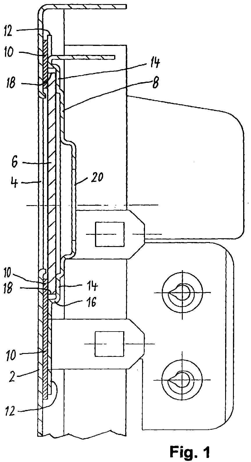
- the drawing shows a broken part of a front of a household appliance, for example, a stove that contains an oven, the heat in the Operation leads to different thermal expansions of the individual parts.
- the domestic appliance has a front part 2 made of sheet metal, in which a through opening 4 is formed.
- the through opening 4 is closed on its back by a plate 6, which on the front part floating "is stored.
- the plate 6 is a
- the display panel is made of a PVC film which is coated with silicone is. This makes the plate 6 easy to clean and scratch-resistant. Its smooth surface sticks however not or only very poorly on adhesive, so that they are not on the front part good adhesive force and cannot be glued permanently or not at all.
- the plate 6 can be a glass plate or Ceramic plate or plastic plate or metal plate or an information display device or the optical scoreboard of a display device. If the plate 6 is translucent or translucent, it can be used to transmit light, either for informational purposes or for lighting the front of the Front parts 2. If the plate 6 is transparent, it can also be used as a sight glass visual observation of the equipment room located behind it.
- a plate holder 8 engages over the edge of the plate 6 and its front part 2 facing away from the plate side and is by a double-sided adhesive tape 10 on glued the front part 2 in an area of the front part 2 which is frame-like extends around the edge of the plate 6.
- the adhesive tape 10 extends from the to the front part 2 glued sections 12 of the plate holder 8 to between Plate 6 and the section of the passage opening 4 opposite it surrounding edge area of the front part 2 and lies with its one adhesive surface the front part 2 and with its other adhesive surface on the edge area of the front Surface of the plate 6.
- a overlapping section 14 of the plate holder 8 On the back of the plate 6 facing away from the adhesive tape 10 is a overlapping section 14 of the plate holder 8.
- the two sections 12 and 14 are connected to each other by a step section 16 of the plate holder 8.
- All Sections 12, 14 and 16 of the plate holder 8 together consist of one single piece of material.
- the step portion 16 surrounds the edge 18 of the plate 6 as a frame and has a small distance from the edge 18 to compensate for Manufacturing tolerances and as a space to compensate for different Material expansions of the plate 6, the front part 2 and the plate holder 8 Temperature increase during oven operation and when the temperature drops after switching off the oven.
- the double-sided adhesive tape 10 is in Cross direction elastically compressible and thereby compensates for manufacturing tolerances and different thermal expansions of the different parts in the transverse direction the plate 6.
- the plate 6 is on the one hand between the overlapping section 14 and the front part 2 with the adhesive tape 10, on the other hand, used without play, preferably slightly clamped.
- the plate holder 8 can have one or more in the area of the through opening 4 Have through openings 20.
- the Plate holder 8 consist of several individual parts, which directly or with Distance are arranged side by side around the plate 6 and each Have sections 12, 14 and 16, one of which on the front part 2 through the double-sided adhesive tape 10 is glued, another on the from Front part 2 facing back part of the plate 6 extends, and the third section 16 connects the other two sections and forms a step that approximates is the same as the thickness of the plate 6.
Landscapes
- Engineering & Computer Science (AREA)
- Textile Engineering (AREA)
- Cookers (AREA)
- Devices For Indicating Variable Information By Combining Individual Elements (AREA)
- Mirrors, Picture Frames, Photograph Stands, And Related Fastening Devices (AREA)
- Supports Or Holders For Household Use (AREA)
- Illuminated Signs And Luminous Advertising (AREA)
- Filters For Electric Vacuum Cleaners (AREA)
Abstract
Hausgerät mit einer Platte (6) über einer Durchgangsöffnung (4). Ein die Platte (6)
übergreifender Plattenhalter (8) ist an dem die Durchgangsöffnung (4) aufweisenden
Geräteteil (2) angeklebt. Die Platte ist auf mindestens einer Plattenseite durch ein
komprimierbares Zwischenelement (10) abgestützt.
Description
Die Erfindung betrifft ein Hausgerät mit einer Durchgangsöffnung in einem Geräteteil und mit einer sich quer über die Durchgangsöffnung erstreckenden Platte gemäß dem Oberbegriff von Anspruch 1.The invention relates to a domestic appliance with a through opening in an appliance part and with a plate extending across the through opening according to the preamble of claim 1.

Die
Der
Eine
Ein festes und dauerhaftes Ankleben der
Hausgeräte erwärmen sich im Betrieb, insbesondere bei Herden oder Backöfen. Hierbei
finden je nach Materialart und Materialform unterschiedliche Wärmeausdehnungen der
einzelnen Teile statt. Dies darf nicht zu Klemmungen und Materialspannungen in der
Durch die Erfindung soll die Aufgabe gelöst werden, eine Möglichkeit zu schaffen, durch welche die Vorteile einer Klebeverbindung ausgenützt werden können, ohne daß die oben genannten Nachteile oder Probleme entstehen.The object of the invention is to create a possibility by which can take advantage of an adhesive bond without the above mentioned disadvantages or problems arise.
Diese Aufgabe wird gemäß den kennzeichnenden Merkmalen von Anspruch 1 dadurch gelöst, daß ein die Platte übergreifender Plattenhalter an dem Geräteteil angeklebt ist, und daß die Platte auf mindestens einer Plattenseite durch ein komprimierbares Zwischenelement abgestützt ist.This object is achieved according to the characterizing features of claim 1 solved that a plate holder overlapping the plate holder is glued to the device part, and that the plate on at least one side of the plate by a compressible Intermediate element is supported.
Das mindestens eine komprimierbare Zwischenelement kann zwischen Plane und Plattenhalter angeordnet sein. Es ist bei der bevorzugten Ausführungsform zwischen der Platte und dem Geräteteil angeordnet.The at least one compressible intermediate element can be between the tarpaulin and Plate holder can be arranged. It is between the preferred embodiment Plate and the device part arranged.
Gemäß einer bevorzugten Ausführungsform der Erfindung ist das Zwischenelement ein doppelseitig klebendes Klebeband.According to a preferred embodiment of the invention, the intermediate element is a double-sided adhesive tape.
Gemäß einer nochmals weiter bevorzugten Ausführungsform ist die Platte mit dem gleichen doppelseitig klebenden Klebeband an dem Geräteteil angeklebt, welches auch das Zwischenelement bildet.According to a further preferred embodiment, the plate is the same double-sided adhesive tape stuck to the device part, which also that Intermediate element forms.
Weitere Merkmale der Erfindung sind in den Unteransprüchen enthalten.Further features of the invention are contained in the subclaims.
Der
Die Erfindung wird im folgenden mit Bezug auf die beigefügte Zeichnung anhand einer bevorzugten Ausführungsform beschrieben. The invention is described below with reference to the accompanying drawing preferred embodiment described.
Die Zeichnung zeigt abgebrochen ein Teil einer Frontseite eines Hausgerätes, beispielsweise eines Herdes, welcher ein Backrohr enthält, dessen Hitze im Betrieb zu unterschiedlichen Wärmeausdehnungen der einzelnen Teile führt.The drawing shows a broken part of a front of a household appliance, for example, a stove that contains an oven, the heat in the Operation leads to different thermal expansions of the individual parts.
Das Hausgerät hat ein Frontteil 2 aus Blech, in welchem eine Durchgangsöffnung 4
gebildet ist. Die Durchgangsöffnung 4 ist auf ihrer Rückseite durch eine Platte 6
verschlossen, welche an dem Frontteil
Für die hier beschriebene Ausführungsform wird angenommen, daß die Platte 6 eine
Display-Platte ist, welche aus einer PVC-Folie besteht, welche mit Silikon beschichtet
ist. Dadurch ist die Platte 6 gut reinigbar und kratzfest. Ihre glatte Oberfläche haftet
jedoch nicht oder nur sehr schlecht an Klebstoff, so daß sie an dem Frontteil nicht mit
guter Haftkraft und nicht dauerhaft oder gar nicht angeklebt werden kann.For the embodiment described here it is assumed that the
Gemäß anderen Ausführungsformen kann die Platte 6 eine Glasplatte oder
Keramikplatte oder Kunststoffplatte oder Metallplatte sein oder ein Informations-Display-Gerät
oder die optische Anzeigetafel eines Display-Gerätes. Wenn die Platte 6
lichtdurchlässig oder durchsichtig ist, kann sie für den Durchlaß von Licht dienen,
entweder für Informationszwecke oder für die Beleuchtung der Frontseite des
Frontteils 2. Wenn die Platte 6 durchsichtig ist, kann sie auch als Schauglas zur
visuellen Beobachtung des hinter ihr befindlichen Geräteraumes dienen.According to other embodiments, the
Ein Plattenhalter 8 übergreift den Rand der Platte 6 und deren vom Frontteil 2
abgewandte Plattenseite und ist durch ein doppelseitig klebendes Klebeband 10 an
den Frontteil 2 angeklebt, in einem Bereich des Frontteils 2, welcher sich rahmenartig
um den Rand der Platte 6 herum erstreckt. Das Klebeband 10 erstreckt sich von den
an den Frontteil 2 angeklebten Abschnitten 12 des Plattenhalters 8 bis zwischen die
Platte 6 und den ihr gegenüber liegenden Abschnitt des die Durchgangsöffnung 4
umgebenden Randbereiches des Frontteils 2 und liegt mit seiner einen Klebefläche an
dem Frontteil 2 und mit seiner anderen Klebefläche an dem Randbereich der vorderen
Oberfläche der Platte 6 an.A
An der vom Klebeband 10 abgewandten Rückseite der Platte 6 liegt ein sie
übergreifender Abschnitt 14 des Plattenhalters 8 an. Die beiden Abschnitte 12 und 14
sind durch einen Stufenabschnitt 16 des Plattenhalters 8 miteinander verbunden. Alle
Abschnitte 12, 14 und 16 des Plattenhalters 8 bestehen zusammen aus einem
einzigen Materialstück. Der Stufenabschnitt 16 umgibt den Rand 18 der Platte 6 wie
ein Rahmen und hat zu dem Rand 18 einen kleinen Abstand zum Ausgleich von
Herstellungstoleranzen und als Zwischenraum zum Ausgleich von unterschiedlichen
Materialausdehnungen der Platte 6, des Frontteils 2 und des Plattenhalters 8 bei
Temperaturerhöhung während des Backofen-Betriebes und bei Temperaturabsenkung
nach dem Abschalten des Backofens. Das doppelseitig klebende Klebeband 10 ist in
Querrichtung elastisch kompressibel und kompensiert dadurch Herstellungstoleranzen
und unterschiedliche Wärmeausdehnungen der verschiedenen Teile in Querrichtung
der Platte 6. Die Platte 6 ist zwischen dem sie übergreifenden Abschnitt 14 einerseits
und dem Frontteil 2 mit dem Klebeband 10 andererseits spielfrei eingesetzt,
vorzugsweise leicht eingespannt.On the back of the
Der Plattenhalter 8 kann im Bereich der Durchgangsöffnung 4 eine oder mehrere
Durchgangsöffnungen 20 aufweisen. Gemäß anderer Ausführungsform kann der
Plattenhalter 8 aus mehreren Einzelteilen bestehen, welche unmittelbar oder mit
Abstand nebeneinander um die Platte 6 herum angeordnet sind und jeweils die
Abschnitte 12, 14 und 16 aufweisen, von welchen einer am Frontteil 2 durch das
doppelseitig klebende Klebeband 10 angeklebt ist, sich ein anderer über die vom
Frontteil 2 abgewandte Rückteil der Platte 6 erstreckt, und der dritte Abschnitt 16 die
beiden anderen Abschnitte miteinander verbindet und eine Stufe bildet, die ungefähr
gleich groß wie die Dicke der Platte 6 ist.The
Claims (10)
dadurch gekennzeichnet, daß ein die Platte (6) übergreifender Plattenhalter (8) an dem Geräteteil (2) angeklebt ist und daß die Platte (6) auf mindestens einer Seite durch ein komprimierbares Zwischenelement (10) abgestützt ist.Household appliance with a through opening (4) in a device part (2) and with a plate (6) extending across the through opening,
characterized in that a plate holder (8) overlapping the plate (6) is glued to the device part (2) and in that the plate (6) is supported on at least one side by a compressible intermediate element (10).
dadurch gekennzeichnet, daß mindestens zwischen der Platte (6) und einem ihr gegenüber liegenden Abschnitt des Geräteteils (2) ein solches Zwischenelement (10) angeordnet ist.Domestic appliance according to claim 1,
characterized in that such an intermediate element (10) is arranged at least between the plate (6) and a section of the device part (2) lying opposite it.
dadurch gekennzeichnet, daß das Zwischenelement ein doppelseitig klebendes Klebeband (10) ist, dessen eine Seite den Geräteteil (2) und dessen andere Seite die Platte (6) kontaktiert.Domestic appliance according to claim 2,
characterized in that the intermediate element is a double-sided adhesive tape (10), one side of which contacts the device part (2) and the other side of which contacts the plate (6).
dadurch gekennzeichnet, daß der Plattenhalter (8) durch ein doppelseitig klebendes Klebeband (10) am Geräteteil (2) angeklebt ist.Domestic appliance according to one of the preceding claims,
characterized in that the plate holder (8) is adhered to the device part (2) by a double-sided adhesive tape (10).
dadurch gekennzeichnet, daß das Klebeband (10), welches zwischen Platte (6) und Geräteteil (2) angeordnet ist, die gleiche Type ist wie das Klebeband, mit welchem der Plattenhalter (8) an dem Geräteteil (2) angeklebt ist.Domestic appliance according to claim 3 or 4,
characterized in that the adhesive tape (10) which is arranged between the plate (6) and the device part (2) is the same type as the adhesive tape with which the plate holder (8) is glued to the device part (2).
dadurch gekennzeichnet, daß das Klebeband (10) sich bis zwischen den Plattenhalter (8) und einen ihm gegenüber liegenden Abschnitt des Geräteteils (2) erstreckt und einerseits am Plattenhalter (8) und andererseits am Geräteteil (2) angeklebt ist, um den Plattenhalter am Geräteteil anzukleben.Domestic appliance according to claim 3,
characterized in that the adhesive tape (10) extends between the plate holder (8) and an opposite section of the device part (2) and is glued on the one hand to the plate holder (8) and on the other hand to the device part (2) to the plate holder on Glue the device part.
dadurch gekennzeichnet, daß die Oberfläche der Platte (6) von einer solchen Art ist, daß an ihr ein Klebemittel nicht ausreichend haften kann, um die Platte (6) dauerhaft an dem Geräteteil (8) anzukleben.Domestic appliance according to one of the preceding claims,
characterized in that the surface of the plate (6) is of such a type that an adhesive cannot adhere to it sufficiently to permanently adhere the plate (6) to the device part (8).
dadurch gekennzeichnet, daß die Platte ein Informations-Display-Gerät ist.Domestic appliance according to one of the preceding claims,
characterized in that the plate is an information display device.
dadurch gekennzeichnet, daß die Platte durchsichtig oder mindestens lichtdurchlässig ist zur Lichtübertragung von einer hinter ihr angeordneten Lichtquelle.Domestic appliance according to one of claims 1 to 7,
characterized in that the plate is transparent or at least translucent for light transmission from a light source arranged behind it.
dadurch gekennzeichnet, daß die Platte ein plattenförmiges Schauglas zur visuellen Beobachtung eines hinter dem Schauglas liegenden Geräteraumes ist.Domestic appliance according to one of claims 1 to 7,
characterized in that the plate is a plate-shaped sight glass for visual observation of an equipment room located behind the sight glass.
Applications Claiming Priority (2)
| Application Number | Priority Date | Filing Date | Title |
|---|---|---|---|
| DE19853053A DE19853053A1 (en) | 1998-11-17 | 1998-11-17 | Home appliance |
| DE19853053 | 1998-11-17 |
Publications (3)
| Publication Number | Publication Date |
|---|---|
| EP1003000A2 true EP1003000A2 (en) | 2000-05-24 |
| EP1003000A3 EP1003000A3 (en) | 2001-08-29 |
| EP1003000B1 EP1003000B1 (en) | 2004-03-17 |
Family
ID=7888128
Family Applications (1)
| Application Number | Title | Priority Date | Filing Date |
|---|---|---|---|
| EP99122260A Expired - Lifetime EP1003000B1 (en) | 1998-11-17 | 1999-11-08 | Domestic appliance |
Country Status (3)
| Country | Link |
|---|---|
| EP (1) | EP1003000B1 (en) |
| AT (1) | ATE262146T1 (en) |
| DE (2) | DE19853053A1 (en) |
Cited By (1)
| Publication number | Priority date | Publication date | Assignee | Title |
|---|---|---|---|---|
| WO2008003778A1 (en) * | 2006-07-07 | 2008-01-10 | BSH Bosch und Siemens Hausgeräte GmbH | Household electrical appliance |
Families Citing this family (1)
| Publication number | Priority date | Publication date | Assignee | Title |
|---|---|---|---|---|
| DE102007055311A1 (en) * | 2007-11-20 | 2009-05-28 | BSH Bosch und Siemens Hausgeräte GmbH | Operating unit for a household appliance and method for producing a control unit |
Family Cites Families (6)
| Publication number | Priority date | Publication date | Assignee | Title |
|---|---|---|---|---|
| US3168089A (en) * | 1963-09-24 | 1965-02-02 | Mills Prod Inc | Oven door window unit |
| DE2810123C2 (en) * | 1978-03-09 | 1985-08-08 | Licentia Patent-Verwaltungs-Gmbh, 6000 Frankfurt | Door to lock the cooking space of a baking and roasting oven with two parallel panes of glass |
| DE8210453U1 (en) * | 1982-04-13 | 1985-11-21 | Bosch-Siemens Hausgeräte GmbH, 7000 Stuttgart | Control panel kit |
| AT396398B (en) * | 1991-11-14 | 1993-08-25 | Vaillant Gmbh | DEVICE FOR HOLDING A SIGHT GLASS |
| DE19622581A1 (en) * | 1996-06-05 | 1997-12-11 | Aeg Hausgeraete Gmbh | Door for closing baking and bread oven with lining |
| DE19701630C1 (en) * | 1997-01-18 | 1998-10-22 | F C Schmidt Gmbh & Co | Cover, especially for household appliances |
-
1998
- 1998-11-17 DE DE19853053A patent/DE19853053A1/en not_active Withdrawn
-
1999
- 1999-11-08 EP EP99122260A patent/EP1003000B1/en not_active Expired - Lifetime
- 1999-11-08 AT AT99122260T patent/ATE262146T1/en not_active IP Right Cessation
- 1999-11-08 DE DE59908867T patent/DE59908867D1/en not_active Expired - Fee Related
Cited By (1)
| Publication number | Priority date | Publication date | Assignee | Title |
|---|---|---|---|---|
| WO2008003778A1 (en) * | 2006-07-07 | 2008-01-10 | BSH Bosch und Siemens Hausgeräte GmbH | Household electrical appliance |
Also Published As
| Publication number | Publication date |
|---|---|
| EP1003000A3 (en) | 2001-08-29 |
| ATE262146T1 (en) | 2004-04-15 |
| EP1003000B1 (en) | 2004-03-17 |
| DE19853053A1 (en) | 2000-05-18 |
| DE59908867D1 (en) | 2004-04-22 |
Similar Documents
| Publication | Publication Date | Title |
|---|---|---|
| DE102009033538A1 (en) | Operating device for an electrical appliance | |
| DE20221918U1 (en) | Optical operating display for a domestic appliance and domestic appliance, in particular built-in domestic appliance | |
| EP0570669A1 (en) | Cooker hob | |
| DE102004046484B4 (en) | Box-shaped control panel | |
| DE10256624A1 (en) | microwave oven | |
| DE202006006612U1 (en) | A method for providing variations of information data in the control panels of domestic appliances has a close fitting cover for part of the control panel carrying the various data | |
| DE102020205864A1 (en) | Display and operating device and household appliance | |
| EP2333421B1 (en) | Display surface element for a domestic appliance | |
| EP1678448B1 (en) | Screen for the housing of an apparatus and method for the production thereof | |
| EP1003000B1 (en) | Domestic appliance | |
| EP0759530B1 (en) | Metallic sheet part, housing ceiling and apparatus cover | |
| DE102011007407A1 (en) | Domestic appliance, particularly refrigerating appliance, has housing and operating condition display that has transparent display panel and is arranged to visible side of housing, where display panel is arranged in front side of background | |
| DE102007006148B4 (en) | laundry machine | |
| DE102004011734A1 (en) | Electric household appliance | |
| EP1731841A1 (en) | Cooking hob with operating device | |
| DE102010030673A1 (en) | Household appliance e.g. household washing machine, has surfaces made of translucent material such that light emitted from lighting device on back side of surfaces is displayed as optical information on front side of surfaces | |
| DE19738504C5 (en) | Door for a household appliance, in particular a household oven | |
| DE19748196A1 (en) | Glazed door for a device with an increased interior temperature | |
| EP0953807A2 (en) | Viewing door for domestic appliance | |
| DE10350745B4 (en) | Device for fixing a printed circuit board of a refrigerator | |
| DE2554381C3 (en) | Control panel for electrical household appliances, in particular for cookers | |
| DE29811084U1 (en) | Viewing door for a household appliance | |
| DE102015112863A1 (en) | Door for a household appliance with a cladding element | |
| DE102007041891A1 (en) | Door for domestic cooker has metal, possibly aluminum, protective element produced by press extrusion | |
| WO1998031864A1 (en) | Screen, in particular for household appliances |
Legal Events
| Date | Code | Title | Description |
|---|---|---|---|
| PUAI | Public reference made under article 153(3) epc to a published international application that has entered the european phase |
Free format text: ORIGINAL CODE: 0009012 |
|
| AK | Designated contracting states |
Kind code of ref document: A2 Designated state(s): AT BE CH CY DE DK ES FI FR GB GR IE IT LI LU MC NL PT SE |
|
| AX | Request for extension of the european patent |
Free format text: AL;LT;LV;MK;RO;SI |
|
| RIN1 | Information on inventor provided before grant (corrected) |
Inventor name: KRUEGER, WERNER Inventor name: SCHALLER, CLEMENS, DR. ING. Inventor name: ERDMANN, KLAUS, DIPL.-ING. (FH) Inventor name: REIFF, UDO |
|
| RIN1 | Information on inventor provided before grant (corrected) |
Inventor name: KRUEGER, WERNER Inventor name: SCHALLER, CLEMENS, DR. ING. Inventor name: ERDMANN, KLAUS, DIPL.-ING. (FH) Inventor name: REIFF, UDO |
|
| PUAL | Search report despatched |
Free format text: ORIGINAL CODE: 0009013 |
|
| AK | Designated contracting states |
Kind code of ref document: A3 Designated state(s): AT BE CH CY DE DK ES FI FR GB GR IE IT LI LU MC NL PT SE |
|
| AX | Request for extension of the european patent |
Free format text: AL;LT;LV;MK;RO;SI |
|
| 17P | Request for examination filed |
Effective date: 20020228 |
|
| AKX | Designation fees paid |
Free format text: AT BE CH CY DE DK ES FI FR GB GR IE IT LI LU MC NL PT SE |
|
| GRAP | Despatch of communication of intention to grant a patent |
Free format text: ORIGINAL CODE: EPIDOSNIGR1 |
|
| GRAS | Grant fee paid |
Free format text: ORIGINAL CODE: EPIDOSNIGR3 |
|
| RAP1 | Party data changed (applicant data changed or rights of an application transferred) |
Owner name: BSH BOSCH UND SIEMENS HAUSGERAETE GMBH |
|
| GRAA | (expected) grant |
Free format text: ORIGINAL CODE: 0009210 |
|
| AK | Designated contracting states |
Kind code of ref document: B1 Designated state(s): AT BE CH CY DE DK ES FI FR GB GR IE IT LI LU MC NL PT SE |
|
| PG25 | Lapsed in a contracting state [announced via postgrant information from national office to epo] |
Ref country code: NL Free format text: LAPSE BECAUSE OF FAILURE TO SUBMIT A TRANSLATION OF THE DESCRIPTION OR TO PAY THE FEE WITHIN THE PRESCRIBED TIME-LIMIT Effective date: 20040317 Ref country code: IE Free format text: LAPSE BECAUSE OF FAILURE TO SUBMIT A TRANSLATION OF THE DESCRIPTION OR TO PAY THE FEE WITHIN THE PRESCRIBED TIME-LIMIT Effective date: 20040317 Ref country code: FI Free format text: LAPSE BECAUSE OF FAILURE TO SUBMIT A TRANSLATION OF THE DESCRIPTION OR TO PAY THE FEE WITHIN THE PRESCRIBED TIME-LIMIT Effective date: 20040317 Ref country code: CY Free format text: LAPSE BECAUSE OF FAILURE TO SUBMIT A TRANSLATION OF THE DESCRIPTION OR TO PAY THE FEE WITHIN THE PRESCRIBED TIME-LIMIT Effective date: 20040317 |
|
| REG | Reference to a national code |
Ref country code: GB Ref legal event code: FG4D Free format text: NOT ENGLISH |
|
| REG | Reference to a national code |
Ref country code: CH Ref legal event code: NV Representative=s name: SIEMENS SCHWEIZ AG Ref country code: CH Ref legal event code: EP |
|
| GBT | Gb: translation of ep patent filed (gb section 77(6)(a)/1977) |
Effective date: 20040317 |
|
| REG | Reference to a national code |
Ref country code: IE Ref legal event code: FG4D Free format text: GERMAN |
|
| REF | Corresponds to: |
Ref document number: 59908867 Country of ref document: DE Date of ref document: 20040422 Kind code of ref document: P |
|
| PG25 | Lapsed in a contracting state [announced via postgrant information from national office to epo] |
Ref country code: SE Free format text: LAPSE BECAUSE OF FAILURE TO SUBMIT A TRANSLATION OF THE DESCRIPTION OR TO PAY THE FEE WITHIN THE PRESCRIBED TIME-LIMIT Effective date: 20040617 Ref country code: GR Free format text: LAPSE BECAUSE OF FAILURE TO SUBMIT A TRANSLATION OF THE DESCRIPTION OR TO PAY THE FEE WITHIN THE PRESCRIBED TIME-LIMIT Effective date: 20040617 Ref country code: DK Free format text: LAPSE BECAUSE OF FAILURE TO SUBMIT A TRANSLATION OF THE DESCRIPTION OR TO PAY THE FEE WITHIN THE PRESCRIBED TIME-LIMIT Effective date: 20040617 |
|
| PG25 | Lapsed in a contracting state [announced via postgrant information from national office to epo] |
Ref country code: ES Free format text: LAPSE BECAUSE OF FAILURE TO SUBMIT A TRANSLATION OF THE DESCRIPTION OR TO PAY THE FEE WITHIN THE PRESCRIBED TIME-LIMIT Effective date: 20040628 |
|
| NLV1 | Nl: lapsed or annulled due to failure to fulfill the requirements of art. 29p and 29m of the patents act | ||
| REG | Reference to a national code |
Ref country code: IE Ref legal event code: FD4D |
|
| ET | Fr: translation filed | ||
| PG25 | Lapsed in a contracting state [announced via postgrant information from national office to epo] |
Ref country code: LU Free format text: LAPSE BECAUSE OF NON-PAYMENT OF DUE FEES Effective date: 20041108 Ref country code: AT Free format text: LAPSE BECAUSE OF NON-PAYMENT OF DUE FEES Effective date: 20041108 |
|
| PG25 | Lapsed in a contracting state [announced via postgrant information from national office to epo] |
Ref country code: MC Free format text: LAPSE BECAUSE OF NON-PAYMENT OF DUE FEES Effective date: 20041130 Ref country code: BE Free format text: LAPSE BECAUSE OF NON-PAYMENT OF DUE FEES Effective date: 20041130 |
|
| PLBE | No opposition filed within time limit |
Free format text: ORIGINAL CODE: 0009261 |
|
| STAA | Information on the status of an ep patent application or granted ep patent |
Free format text: STATUS: NO OPPOSITION FILED WITHIN TIME LIMIT |
|
| 26N | No opposition filed |
Effective date: 20041220 |
|
| BERE | Be: lapsed |
Owner name: BOSCH UND SIEMENS HAUSGERATE G.M.B.H. *BSH Effective date: 20041130 |
|
| BERE | Be: lapsed |
Owner name: BOSCH UND SIEMENS HAUSGERATE G.M.B.H. *BSH Effective date: 20041130 |
|
| PG25 | Lapsed in a contracting state [announced via postgrant information from national office to epo] |
Ref country code: PT Free format text: LAPSE BECAUSE OF NON-PAYMENT OF DUE FEES Effective date: 20040817 |
|
| PGFP | Annual fee paid to national office [announced via postgrant information from national office to epo] |
Ref country code: DE Payment date: 20071130 Year of fee payment: 9 |
|
| PGFP | Annual fee paid to national office [announced via postgrant information from national office to epo] |
Ref country code: IT Payment date: 20071127 Year of fee payment: 9 Ref country code: CH Payment date: 20071126 Year of fee payment: 9 |
|
| PGFP | Annual fee paid to national office [announced via postgrant information from national office to epo] |
Ref country code: GB Payment date: 20071123 Year of fee payment: 9 Ref country code: FR Payment date: 20071120 Year of fee payment: 9 |
|
| REG | Reference to a national code |
Ref country code: CH Ref legal event code: PCAR Free format text: SIEMENS SCHWEIZ AG;INTELLECTUAL PROPERTY FREILAGERSTRASSE 40;8047 ZUERICH (CH) |
|
| REG | Reference to a national code |
Ref country code: CH Ref legal event code: PL |
|
| GBPC | Gb: european patent ceased through non-payment of renewal fee |
Effective date: 20081108 |
|
| PG25 | Lapsed in a contracting state [announced via postgrant information from national office to epo] |
Ref country code: IT Free format text: LAPSE BECAUSE OF NON-PAYMENT OF DUE FEES Effective date: 20081108 |
|
| REG | Reference to a national code |
Ref country code: FR Ref legal event code: ST Effective date: 20090731 |
|
| PG25 | Lapsed in a contracting state [announced via postgrant information from national office to epo] |
Ref country code: LI Free format text: LAPSE BECAUSE OF NON-PAYMENT OF DUE FEES Effective date: 20081130 Ref country code: DE Free format text: LAPSE BECAUSE OF NON-PAYMENT OF DUE FEES Effective date: 20090603 Ref country code: CH Free format text: LAPSE BECAUSE OF NON-PAYMENT OF DUE FEES Effective date: 20081130 |
|
| PG25 | Lapsed in a contracting state [announced via postgrant information from national office to epo] |
Ref country code: GB Free format text: LAPSE BECAUSE OF NON-PAYMENT OF DUE FEES Effective date: 20081108 |
|
| PG25 | Lapsed in a contracting state [announced via postgrant information from national office to epo] |
Ref country code: FR Free format text: LAPSE BECAUSE OF NON-PAYMENT OF DUE FEES Effective date: 20081130 |