EP1003031B1 - Pneumatisches Bremssytem und Methode zur Detektion der Verunreinigung von Luft durch Öl in einem solchen Bremssystem - Google Patents
Pneumatisches Bremssytem und Methode zur Detektion der Verunreinigung von Luft durch Öl in einem solchen Bremssystem Download PDFInfo
- Publication number
- EP1003031B1 EP1003031B1 EP99119050A EP99119050A EP1003031B1 EP 1003031 B1 EP1003031 B1 EP 1003031B1 EP 99119050 A EP99119050 A EP 99119050A EP 99119050 A EP99119050 A EP 99119050A EP 1003031 B1 EP1003031 B1 EP 1003031B1
- Authority
- EP
- European Patent Office
- Prior art keywords
- resistor
- brake system
- air
- oil
- oil contamination
- Prior art date
- Legal status (The legal status is an assumption and is not a legal conclusion. Google has not performed a legal analysis and makes no representation as to the accuracy of the status listed.)
- Expired - Lifetime
Links
- 238000011109 contamination Methods 0.000 title claims description 33
- 238000000034 method Methods 0.000 title claims description 9
- 238000001514 detection method Methods 0.000 claims description 16
- OKTJSMMVPCPJKN-UHFFFAOYSA-N Carbon Chemical group [C] OKTJSMMVPCPJKN-UHFFFAOYSA-N 0.000 claims description 13
- 230000007423 decrease Effects 0.000 claims description 5
- 238000009835 boiling Methods 0.000 claims description 4
- 238000010438 heat treatment Methods 0.000 claims description 4
- 238000005286 illumination Methods 0.000 claims 1
- 239000003921 oil Substances 0.000 description 34
- 239000002274 desiccant Substances 0.000 description 12
- 239000007789 gas Substances 0.000 description 8
- 229910052799 carbon Inorganic materials 0.000 description 7
- 238000010586 diagram Methods 0.000 description 6
- 238000003763 carbonization Methods 0.000 description 4
- 239000000446 fuel Substances 0.000 description 4
- 239000000523 sample Substances 0.000 description 4
- 239000000356 contaminant Substances 0.000 description 3
- 230000003247 decreasing effect Effects 0.000 description 3
- 238000009434 installation Methods 0.000 description 3
- 238000005259 measurement Methods 0.000 description 3
- 238000004891 communication Methods 0.000 description 2
- 238000007710 freezing Methods 0.000 description 2
- 230000008014 freezing Effects 0.000 description 2
- 239000007788 liquid Substances 0.000 description 2
- 238000012360 testing method Methods 0.000 description 2
- 238000010521 absorption reaction Methods 0.000 description 1
- 238000009825 accumulation Methods 0.000 description 1
- 230000001419 dependent effect Effects 0.000 description 1
- 238000011156 evaluation Methods 0.000 description 1
- -1 gasoline Chemical class 0.000 description 1
- 229930195733 hydrocarbon Natural products 0.000 description 1
- 150000002430 hydrocarbons Chemical class 0.000 description 1
- 239000010687 lubricating oil Substances 0.000 description 1
- 230000014759 maintenance of location Effects 0.000 description 1
- 239000000463 material Substances 0.000 description 1
- 238000012986 modification Methods 0.000 description 1
- 230000004048 modification Effects 0.000 description 1
- 238000012544 monitoring process Methods 0.000 description 1
- 239000002245 particle Substances 0.000 description 1
- 230000011664 signaling Effects 0.000 description 1
- 239000000126 substance Substances 0.000 description 1
- 230000008961 swelling Effects 0.000 description 1
- 238000002076 thermal analysis method Methods 0.000 description 1
Images

Classifications
-
- B—PERFORMING OPERATIONS; TRANSPORTING
- B60—VEHICLES IN GENERAL
- B60R—VEHICLES, VEHICLE FITTINGS, OR VEHICLE PARTS, NOT OTHERWISE PROVIDED FOR
- B60R16/00—Electric or fluid circuits specially adapted for vehicles and not otherwise provided for; Arrangement of elements of electric or fluid circuits specially adapted for vehicles and not otherwise provided for
- B60R16/02—Electric or fluid circuits specially adapted for vehicles and not otherwise provided for; Arrangement of elements of electric or fluid circuits specially adapted for vehicles and not otherwise provided for electric constitutive elements
- B60R16/023—Electric or fluid circuits specially adapted for vehicles and not otherwise provided for; Arrangement of elements of electric or fluid circuits specially adapted for vehicles and not otherwise provided for electric constitutive elements for transmission of signals between vehicle parts or subsystems
- B60R16/0231—Circuits relating to the driving or the functioning of the vehicle
- B60R16/0232—Circuits relating to the driving or the functioning of the vehicle for measuring vehicle parameters and indicating critical, abnormal or dangerous conditions
Definitions
- This application relates to a vehicular pneumatic brake system and a method for detecting oil contamination in a vehicular pneumatic brake system.
- pneumatic brake systems sometimes referred to as compressed air brake systems, use air pressure to actuate the brakes of the heavy vehicle.
- pneumatic brake systems include an air compressor and an air dryer.
- the air compressor includes a cylinder, a piston which reciprocates within the cylinder, and a piston seal disposed between the outer circumference of the piston and the inner circumference of the cylinder. The reciprocating movement of the piston is used to compress or pressurize the brake system air supply.
- the air dryer includes a canister filled with desiccant to remove moisture and other contaminants from the air supply. Periodically, the canister is purged to remove the moisture absorbed by the desiccant.
- Pneumatic brake systems often experience an oil contamination condition, commonly referred to as "blow-by".
- This type of contamination occurs when lubricating oil located on one side of the air compressor piston is blown by the piston seal into the brake system air supply located on the opposing side of the piston.
- the oil is absorbed by the desiccant.
- oil absorbed by the desiccant cannot be purged out of the air dryer.
- the absorption and retention of an increasing amount of oil prevents the desiccant from absorbing additional moisture, thereby allowing some moisture to pass through the air dryer into other portions of the brake system. This non-absorbed moisture can freeze inside the brake system during cold temperature conditions and damage many brake system components.
- the air dryer To avoid brake system damage caused by oil contamination, the air dryer must be periodically serviced by replacing the desiccant canister. Determining when to service the air dryer for excessive oil contamination is a difficult task. Accordingly, it would be desirable to provide an oil contamination detection assembly for detecting when service of the air dryer for oil contamination is necessary.
- US-Patent 5,730,942 discloses a system for measuring the content of foreign substances in a gas stream, for example oil in a stream of compressed air.
- the system includes at least one probe for collecting a given amount of gas.
- the probe there is at least one sensor over which the sampled gas is passed.
- the sensor includes a temperature sensor for determining the temperature of the gas sample flowing past it, and a detector whose electrical resistivity or conductivity depends on the oil content of the gas stream.
- US-Patent 4,631,952 discloses an apparatus for sensing organic liquids, vapors and gases which includes a resistivity sensor means comprising an intimate admixture of conductive particles and a material capable of swelling in the presence of the liquid, gas or vapor to be detected and an electrical contact thereto.
- the sensor is in particular used to sense hydrocarbons, such as gasoline, leaking from an underground tank into the environment.
- US-Patent 4,078,880 discloses an apparatus for detecting non-combusted fuel components in exhaust gases of a heating installation comprising a collector for collecting the non-combusted fuel components.
- the collector is provided with a probe serving to generate an electrical signal dependent upon the quantity of collected fuel components and with an electrical operating element for the removal of the collected fuel components.
- the apparatus is in particular used in combination with an oil heating installation.
- the sensor includes a temperature sensitive resistor, a heating electrode and electrodes for the contamination measurement.
- the accumulated contamination is measured during a measurement cycle.
- a test phase is started.
- a thermo-analysis is carried out during the test phase and thereafter the sensor is heated up to 550 to 700° C for the pyrolytic-selfcleaning.
- the invention provides a vehicular pneumatic brake system having the features of claim 1.
- the invention further provides a method for detecting a predetermined level of oil contamination in a vehicular pneumatic brake system, comprising the features of claim 8.
- FIG. 1 is a schematic diagram of a portion of a vehicular pneumatic brake system 10, sometimes referred to as a compressed air brake system.
- the brake system 10 includes an air compressor 12 for pressurizing or compressing an air supply, an air dryer assembly 14 for removing moisture and other contaminants from the air supply, and a reservoir 16 for storing the air supply.
- the air compressor 12 is in pneumatic communication with the air dryer assembly 14 via a first pneumatic line 18.
- the air dryer assembly 14 is in pneumatic communication with the reservoir 16 via a second pneumatic line 20.
- the air compressor 12 typically receives air from an engine intake manifold or an air filter (not shown) and compresses the air, thereby forcing the compressed air through the first pneumatic line 18 to the air dryer assembly 14.
- the air dryer assembly 14 includes an inlet port 22 which receives the air from the first pneumatic line 18, a replaceable desiccant canister 24 which removes moisture and other contaminants, such as oil, from the air passing through the assembly 14, an air dryer heater 26 which warms the air passing through the assembly 14, thereby preventing the moisture captured in the canister 24 from freezing during cold temperature conditions, and an outlet port 28 which delivers the heated, moisture and contaminant-free, compressed air into the second pneumatic line 20.
- the second pneumatic line 20 directs the compressed air into the reservoir 16 for storage.
- the compressed air stored in the reservoir 16 is used to supply air pressure to the brakes of a vehicle (not shown).
- FIG. 2 is an electrical schematic diagram of a first embodiment of an oil contamination detection assembly 30 in accordance with the present invention.
- the detection assembly 30 is preferably installed in either the first or second pneumatic line 18 or 20.
- the detection assembly 30 is particularly adapted for use in the vehicular pneumatic brake system 10 having a supply of air contaminated with oil consisting of carbon and other non-carbon elements.
- the detection assembly 30 includes a first resistor 32, having a known resistance, which is exposed to the air of the brake system 10. As a result of this exposure, the first resistor 32 accumulates a layer of the contaminating oil.
- the first resistor 32 is preferably installed in either the first or second pneumatic line 18 or 20.
- a carbonization heater 34 is used to warm or heat the first resistor 32, preferably to approximately 300 F. This application of heat boils the non-carbon elements off the first resistor 32, leaving a carbon residue which decreases the resistance of the first resistor 32. As more and more oil accumulates on the first resistor 32, the amount of carbon residue increases, thereby further decreasing the resistance of the first resistor 32.
- the carbonization heater 34 is connected to an ignition circuit 36 used to supply power to the air dryer heater 26 located within the dryer assembly 14.
- the ignition circuit 36 is also connected to a voltage regulator 40 designed to supply a constant five volt power source.
- a threshold detector circuit 42 includes a second resistor 44 and a comparator circuit 46 to produce an oil contamination warning signal when the resistance of the first resistor 32 is less than a predetermined value.
- the second resistor 44 which is warmed by the carbonization heater 34 to the same temperature as the first resistor 32, is connected in series between the first resistor 32 and ground to form a voltage divider circuit 48.
- the voltage divider circuit 48 produces a measuring signal proportional to the resistance of the first resistor 32.
- the comparator circuit 46 receives the measuring signal and produces the oil contamination warning signal when the measuring signal is less than the predetermined value.
- the predetermined value is adjustable and may be set so as to correlate with a specific level of oil contamination within the desiccant canister 24.
- the detection assembly 30 produces an adjustable oil contamination warning signal which indicates when the desiccant canister 24 should be serviced or replaced.
- the oil contamination warning signal illuminates an oil contamination warning indicator 50, preferably an LED (light emitting diode) as illustrated in Figure 2, having adjacent indicia (not shown) which instructs replacement of the desiccant canister 24.
- the warning signal is also transmitted to an electrical output terminal 52, preferably to illuminate a second warning indicator within the line of sight of a vehicle operator.
- the oil contamination detection assembly 30 is reset by removing the carbon residue from the first resistor 32 or by replacing the first resistor 32.
- the first resistor 32 is preferably housed in a cartridge 54 which is replaceable in a manner similar to a fuse.
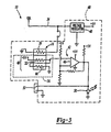
- FIG. 3 is an electrical schematic diagram of a second embodiment of an oil contamination detection assembly 60 in accordance with the present invention.
- the detection assembly 60 is preferably integrated into the air dryer assembly 14 of the brake system 10.
- the air dryer heater 26, located in the air dryer assembly 14 is used in a conventional manner (i.e. to heat the air passing through the air dryer assembly 14 so as to prevent the moisture absorbed by desiccant within the air dryer assembly 14 from freezing during cold climate conditions) and to boil the non-carbon elements off the first resistor 32.
- a separate carbonization heater is not required.
- the second embodiment detection system 60 operates similar to the first embodiment detection system 30.
- an inventive method for detecting a predetermined level of oil contamination in a vehicular pneumatic brake system having a supply of air contaminated with oil consisting of carbon and other non-carbon elements includes the steps of: exposing a resistor having a measured resistance to the air of the brake system, accumulating a layer of the oil on the resistor, boiling the non-carbon elements off the resistor with a heater leaving a carbon residue on the resistor which decreases the resistance of the resistor, determining the decreased resistance of the resistor, and producing an oil contamination warning signal in response to the decreased resistance of the resistor being less than a predetermined value.
- the method further includes the step of illuminating an oil contamination warning indicator in response to the warning signal.
Landscapes
- Engineering & Computer Science (AREA)
- Automation & Control Theory (AREA)
- Mechanical Engineering (AREA)
- Valves And Accessory Devices For Braking Systems (AREA)
- Braking Arrangements (AREA)
Claims (9)
- Druckluftbremsanlage (10) für ein Fahrzeug, wobei die Bremsanlage folgendes umfaßt:einen Drucklufterzeuger (12),einen Vorratsbehälter (16) für die Zufuhr von Druckluft zu den Bremsen,wenigstens eine Leitung (18, 20), die Luft zwischen dem Kompressor (12) und dem Vorratsbehälter (16) befördert,eine Baugruppe zum Erfassen einer Ölkontamination mit einem ersten Widerstand (32), der einen gemessenen Widerstand hat und in der Bremsanlage so positioniert ist, daß er der Luft der Bremsanlage ausgesetzt ist und eine Schicht des die Luft verunreinigenden Öls ansammelt, undeine Schaltung zum Erzeugen eines Warnsignals für eine Ölkontamination in Reaktion darauf, daß der Widerstand des ersten Widerstands kleiner ist als ein vorbestimmter Wert.
- Bremsanlage nach Anspruch 1 mit einer Heizvorrichtung, um durch Kochen Elemente vom ersten Widerstand (32) zu entfernen, um einen Kohlerückstand zu hinterlassen, der den Widerstand des ersten Widerstands (32) herabsetzt.
- Bremsanlage nach Anspruch 2 mit einer Warnanzeige (50) für eine Ölkontamination, die in Reaktion auf das Warnsignal beleuchtet wird.
- Bremsanlage nach Anspruch 2, bei der die Schaltung (42) eine Schwellwerterfassungsschaltung (42) ist, die einen zweiten Widerstand (44) umfaßt, der mit dem ersten Widerstand (32) in Reihe geschaltet ist, um eine Spannungsteilerschaltung (48) zum Erzeugen eines Meßsignals proportional zum Widerstand des ersten Widerstands (32) zu bilden.
- Bremsanlage nach Anspruch 4, bei der die Erfassungsschaltung (42) eine Vergleichsschaltung (46) umfaßt zum Empfangen des Meßsignals und zum Erzeugen des Warnsignals in Reaktion darauf, daß das Meßsignal kleiner ist als der vorbestimmte Wert.
- Bremsanlage nach Anspruch 2 mit einer Lufttrocknerbaugruppe (14), wobei die Baugruppe (30) zum Erfassen einer Ölkontamination in die Lufttrocknerbaugruppe (14) integriert ist.
- Bremsanlage nach Anspruch 6, bei der die Lufttrocknerbaugruppe (14) eine Lufttrockner-Heizvorrichtung (26) zum Erwärmen der Luft der Bremsanlage und zum Auskochen von Elementen des ersten Widerstands (32) umfaßt.
- Verfahren zum Erfassen eines vorbestimmten Grads der Ölkontamination in der Druckluftbremsanlage eines Fahrzeugs, in der sich mit Öl kontaminierte Luft befindet, wobei das Verfahren die folgenden Schritte umfaßt:ein Widerstand (32) mit einem gemessenen Widerstand wird der Luft der Bremsanlage ausgesetzt;eine Schicht des Öls wird auf dem Widerstand (32) angesammelt;mit einer Heizvorrichtung werden Elemente durch Kochen vom Widerstand (32) entfernt, so daß ein Kohlerückstand auf dem Widerstand zurückbleibt, um den Widerstand des Widerstands (32) herabzusetzen; undein Warnsignal für eine Ölkontamination wird in Reaktion darauf erzeugt, daß der Widerstand des Widerstands (32) kleiner ist als ein vorbestimmter Wert.
- Verfahren nach Anspruch 8 mit dem Schritt des Beleuchtens einer Warnanzeige für eine Ölkontamination in Reaktion auf das Warnsignal.
Applications Claiming Priority (2)
| Application Number | Priority Date | Filing Date | Title |
|---|---|---|---|
| US09/168,058 US5986546A (en) | 1998-10-07 | 1998-10-07 | Oil contamination detection assembly |
| US168058 | 1998-10-07 |
Publications (3)
| Publication Number | Publication Date |
|---|---|
| EP1003031A2 EP1003031A2 (de) | 2000-05-24 |
| EP1003031A3 EP1003031A3 (de) | 2000-07-26 |
| EP1003031B1 true EP1003031B1 (de) | 2003-05-07 |
Family
ID=22609928
Family Applications (1)
| Application Number | Title | Priority Date | Filing Date |
|---|---|---|---|
| EP99119050A Expired - Lifetime EP1003031B1 (de) | 1998-10-07 | 1999-09-29 | Pneumatisches Bremssytem und Methode zur Detektion der Verunreinigung von Luft durch Öl in einem solchen Bremssystem |
Country Status (3)
| Country | Link |
|---|---|
| US (1) | US5986546A (de) |
| EP (1) | EP1003031B1 (de) |
| DE (1) | DE69907608T2 (de) |
Families Citing this family (10)
| Publication number | Priority date | Publication date | Assignee | Title |
|---|---|---|---|---|
| DE10046900C1 (de) * | 2000-09-21 | 2002-05-23 | Fujitsu Siemens Computers Gmbh | Schaltungsbaustein |
| US6840093B2 (en) | 2002-04-05 | 2005-01-11 | Caterpillar Inc. | System and method for determining oil grade |
| US6675635B2 (en) | 2002-04-17 | 2004-01-13 | Caterpillar Inc | System and method for determining oil quality |
| US20040012490A1 (en) * | 2002-07-16 | 2004-01-22 | Chen Liang Wen | Brake alarm device |
| EP2094534B1 (de) * | 2006-12-19 | 2014-03-05 | Renault Trucks | Antriebsstrangeinheit, verfahren zur steuerung solch einer einheit und mit solch einer einheit versehenes kraftfahrzeug |
| US7857882B1 (en) | 2007-12-13 | 2010-12-28 | Johnson Welded Products Inc. | Water and oil mist elimination apparatus for a vehicular compressed air storage system |
| CN102812318B (zh) * | 2009-09-28 | 2016-01-06 | 皇家飞利浦电子股份有限公司 | 用于液化和存储流体的系统和方法 |
| US11428683B2 (en) * | 2020-04-21 | 2022-08-30 | Pratt & Whitney Canada Corp. | Method of identifying a source component of particulate debris in an aircraft engine |
| US11428684B2 (en) * | 2020-04-21 | 2022-08-30 | Pratt & Whitney Canada Corp. | Method of identifying a source component of particulate debris in an aircraft engine |
| CN114046553A (zh) * | 2021-11-29 | 2022-02-15 | 广东万和电气有限公司 | 一种油烟机及油污检测方法 |
Family Cites Families (8)
| Publication number | Priority date | Publication date | Assignee | Title |
|---|---|---|---|---|
| CH598601A5 (de) * | 1975-07-10 | 1978-05-12 | Richard Hunziker | |
| US4316640A (en) * | 1980-06-13 | 1982-02-23 | Bi-Modal Corporation | Electro pneumatic brake system for railway car |
| JPS61111450A (ja) * | 1984-11-05 | 1986-05-29 | Toyota Central Res & Dev Lab Inc | オイルミスト検出装置 |
| US4631952A (en) * | 1985-08-30 | 1986-12-30 | Chevron Research Company | Resistive hydrocarbon leak detector |
| GB8525774D0 (en) * | 1985-10-18 | 1985-11-20 | Domnick Hunter Filters Ltd | Detecting oil aerosol |
| US5076056A (en) * | 1990-08-01 | 1991-12-31 | Allied Signal Inc. | Enhanced pneumatic brake system |
| US5494342A (en) * | 1994-06-14 | 1996-02-27 | New York Air Brake Corporation | Electropneumatic brake control system |
| DE4445102A1 (de) * | 1994-12-17 | 1996-06-27 | Mann & Hummel Filter | Anordnung zur Ermittlung von Fremdstoffanteilen in einem Gasstrom |
-
1998
- 1998-10-07 US US09/168,058 patent/US5986546A/en not_active Expired - Fee Related
-
1999
- 1999-09-29 EP EP99119050A patent/EP1003031B1/de not_active Expired - Lifetime
- 1999-09-29 DE DE69907608T patent/DE69907608T2/de not_active Expired - Fee Related
Also Published As
| Publication number | Publication date |
|---|---|
| US5986546A (en) | 1999-11-16 |
| EP1003031A3 (de) | 2000-07-26 |
| DE69907608T2 (de) | 2004-02-19 |
| DE69907608D1 (de) | 2003-06-12 |
| EP1003031A2 (de) | 2000-05-24 |
Similar Documents
| Publication | Publication Date | Title |
|---|---|---|
| EP1003031B1 (de) | Pneumatisches Bremssytem und Methode zur Detektion der Verunreinigung von Luft durch Öl in einem solchen Bremssystem | |
| EP1813491B1 (de) | Luftsystem für ein Fahrzeug mit Anzeigevorrichtung, Lufttrockner und Verfahren | |
| US4522712A (en) | Double-ended, spin-on fuel water separator | |
| EP0789836B1 (de) | Vorrichtung und verfahren zur detektion eines lecks in einem verdampfungsemissionssteuerungssystem | |
| CA1239592A (en) | Single-ended spin-on fuel water separator | |
| US5789665A (en) | Oil quality sensor for use in a motor | |
| JP2901516B2 (ja) | 燃料蒸気処理装置及びその診断方法 | |
| US5107698A (en) | Smoke generating apparatus and method for in situ vacuum leak detection | |
| US5257008A (en) | Compressed air system with warning mechanism for air dryer service life indication | |
| KR20180080752A (ko) | 매연측정장치 | |
| JPH07158520A (ja) | 蒸発性パージ流量モニタリングシステム | |
| US20140324284A1 (en) | Evaporative Emission Control System Monitoring | |
| US8277118B2 (en) | Drop counter and flow meter for apparatus and method for determining the thermal stability of fluids | |
| CN103123308B (zh) | 热空气加热式柴油车排污物分析仪的前置样气处理装置 | |
| EP0992413B1 (de) | Feststellungsvorrichtung für Ölverunreinigung | |
| US20150120165A1 (en) | Evaporative Emission Control System Monitoring | |
| CA2127594C (en) | Apparatus and method for non-intrusive testing of a motor vehicle canister purge system | |
| WO2007060418A1 (en) | Method for monitoring the degree of clogging of the filtration surface of an oil filter | |
| HU201705B (en) | Vehicle air dryer with control gear particularly for pressure air systems | |
| Kriek et al. | Development of emission factors for polyamide processing | |
| FR3166096A1 (fr) | Vehicule automobile comprenant un calculateur de detection de fuite d’un circuit de climatisation en fonction de l’etat d’allumage du compresseur, procede et programme sur la base d’un tel vehicule | |
| EP3077787B1 (de) | Verfahren zur analyse einer flüssigkeit mit einer einheit zur entnahme einer flüssigkeitsprobe zum einbau in einem system mit temperaturschwankungen | |
| EP2067946A1 (de) | Verfahren und System zur Detektion der Verdünnung des Schmiermittels durch den Brennstoff | |
| EP3077786A1 (de) | Einheit zur entnahme einer flüssigkeitsprobe zum einsetzen in ein system mit druckschwankungen | |
| JPH0526136U (ja) | エアドライヤの乾燥剤交換時期表示装置 |
Legal Events
| Date | Code | Title | Description |
|---|---|---|---|
| PUAI | Public reference made under article 153(3) epc to a published international application that has entered the european phase |
Free format text: ORIGINAL CODE: 0009012 |
|
| AK | Designated contracting states |
Kind code of ref document: A2 Designated state(s): DE FR GB IT SE |
|
| AX | Request for extension of the european patent |
Free format text: AL;LT;LV;MK;RO;SI |
|
| PUAL | Search report despatched |
Free format text: ORIGINAL CODE: 0009013 |
|
| RIC1 | Information provided on ipc code assigned before grant |
Free format text: 7G 01N 27/04 A, 7G 01N 31/12 B, 7B 60T 17/22 B |
|
| AK | Designated contracting states |
Kind code of ref document: A3 Designated state(s): AT BE CH CY DE DK ES FI FR GB GR IE IT LI LU MC NL PT SE |
|
| AX | Request for extension of the european patent |
Free format text: AL;LT;LV;MK;RO;SI |
|
| 17P | Request for examination filed |
Effective date: 20010116 |
|
| AKX | Designation fees paid |
Free format text: DE FR GB IT SE |
|
| 17Q | First examination report despatched |
Effective date: 20010619 |
|
| RTI1 | Title (correction) |
Free format text: VEHICULAR PNEUMATIC BRAKE SYSTEM AND METHOD FOR DETECTING OIL CONTAMINATION IN SUCH A BRAKE SYSTEM |
|
| GRAH | Despatch of communication of intention to grant a patent |
Free format text: ORIGINAL CODE: EPIDOS IGRA |
|
| GRAH | Despatch of communication of intention to grant a patent |
Free format text: ORIGINAL CODE: EPIDOS IGRA |
|
| GRAA | (expected) grant |
Free format text: ORIGINAL CODE: 0009210 |
|
| AK | Designated contracting states |
Designated state(s): DE FR GB IT SE |
|
| REG | Reference to a national code |
Ref country code: GB Ref legal event code: FG4D |
|
| REF | Corresponds to: |
Ref document number: 69907608 Country of ref document: DE Date of ref document: 20030612 Kind code of ref document: P |
|
| REG | Reference to a national code |
Ref country code: SE Ref legal event code: TRGR |
|
| ET | Fr: translation filed | ||
| PLBE | No opposition filed within time limit |
Free format text: ORIGINAL CODE: 0009261 |
|
| STAA | Information on the status of an ep patent application or granted ep patent |
Free format text: STATUS: NO OPPOSITION FILED WITHIN TIME LIMIT |
|
| 26N | No opposition filed |
Effective date: 20040210 |
|
| PGFP | Annual fee paid to national office [announced via postgrant information from national office to epo] |
Ref country code: FR Payment date: 20050919 Year of fee payment: 7 |
|
| PGFP | Annual fee paid to national office [announced via postgrant information from national office to epo] |
Ref country code: SE Payment date: 20050921 Year of fee payment: 7 Ref country code: GB Payment date: 20050921 Year of fee payment: 7 |
|
| PGFP | Annual fee paid to national office [announced via postgrant information from national office to epo] |
Ref country code: DE Payment date: 20051031 Year of fee payment: 7 |
|
| PG25 | Lapsed in a contracting state [announced via postgrant information from national office to epo] |
Ref country code: SE Free format text: LAPSE BECAUSE OF NON-PAYMENT OF DUE FEES Effective date: 20060930 |
|
| PGFP | Annual fee paid to national office [announced via postgrant information from national office to epo] |
Ref country code: IT Payment date: 20060930 Year of fee payment: 8 |
|
| PG25 | Lapsed in a contracting state [announced via postgrant information from national office to epo] |
Ref country code: DE Free format text: LAPSE BECAUSE OF NON-PAYMENT OF DUE FEES Effective date: 20070403 |
|
| EUG | Se: european patent has lapsed | ||
| GBPC | Gb: european patent ceased through non-payment of renewal fee |
Effective date: 20060929 |
|
| REG | Reference to a national code |
Ref country code: FR Ref legal event code: ST Effective date: 20070531 |
|
| PG25 | Lapsed in a contracting state [announced via postgrant information from national office to epo] |
Ref country code: GB Free format text: LAPSE BECAUSE OF NON-PAYMENT OF DUE FEES Effective date: 20060929 |
|
| PG25 | Lapsed in a contracting state [announced via postgrant information from national office to epo] |
Ref country code: FR Free format text: LAPSE BECAUSE OF NON-PAYMENT OF DUE FEES Effective date: 20061002 |
|
| PG25 | Lapsed in a contracting state [announced via postgrant information from national office to epo] |
Ref country code: IT Free format text: LAPSE BECAUSE OF NON-PAYMENT OF DUE FEES Effective date: 20070929 |