EP1003036B1 - Chromatographieverfahren - Google Patents
Chromatographieverfahren Download PDFInfo
- Publication number
- EP1003036B1 EP1003036B1 EP99922518A EP99922518A EP1003036B1 EP 1003036 B1 EP1003036 B1 EP 1003036B1 EP 99922518 A EP99922518 A EP 99922518A EP 99922518 A EP99922518 A EP 99922518A EP 1003036 B1 EP1003036 B1 EP 1003036B1
- Authority
- EP
- European Patent Office
- Prior art keywords
- withdrawal
- fraction
- component
- packing bed
- packing
- Prior art date
- Legal status (The legal status is an assumption and is not a legal conclusion. Google has not performed a legal analysis and makes no representation as to the accuracy of the status listed.)
- Expired - Lifetime
Links
- 238000000034 method Methods 0.000 title claims description 77
- 238000004587 chromatography analysis Methods 0.000 title description 2
- 238000012856 packing Methods 0.000 claims abstract description 200
- 239000000463 material Substances 0.000 claims abstract description 66
- 239000012530 fluid Substances 0.000 claims abstract description 63
- 238000011144 upstream manufacturing Methods 0.000 claims abstract description 13
- 238000013375 chromatographic separation Methods 0.000 claims description 33
- 230000008569 process Effects 0.000 claims description 29
- 238000010977 unit operation Methods 0.000 claims description 2
- 239000003480 eluent Substances 0.000 abstract description 89
- 238000000926 separation method Methods 0.000 abstract description 62
- 239000000243 solution Substances 0.000 description 68
- 210000003918 fraction a Anatomy 0.000 description 48
- 210000000540 fraction c Anatomy 0.000 description 46
- 210000002196 fr. b Anatomy 0.000 description 37
- 238000011084 recovery Methods 0.000 description 28
- 239000007788 liquid Substances 0.000 description 26
- 238000007796 conventional method Methods 0.000 description 18
- 239000007787 solid Substances 0.000 description 18
- WQZGKKKJIJFFOK-GASJEMHNSA-N Glucose Natural products OC[C@H]1OC(O)[C@H](O)[C@@H](O)[C@@H]1O WQZGKKKJIJFFOK-GASJEMHNSA-N 0.000 description 17
- 239000008103 glucose Substances 0.000 description 17
- 239000000203 mixture Substances 0.000 description 17
- OWEGMIWEEQEYGQ-UHFFFAOYSA-N 100676-05-9 Natural products OC1C(O)C(O)C(CO)OC1OCC1C(O)C(O)C(O)C(OC2C(OC(O)C(O)C2O)CO)O1 OWEGMIWEEQEYGQ-UHFFFAOYSA-N 0.000 description 15
- GUBGYTABKSRVRQ-PICCSMPSSA-N Maltose Natural products O[C@@H]1[C@@H](O)[C@H](O)[C@@H](CO)O[C@@H]1O[C@@H]1[C@@H](CO)OC(O)[C@H](O)[C@H]1O GUBGYTABKSRVRQ-PICCSMPSSA-N 0.000 description 15
- 230000000052 comparative effect Effects 0.000 description 13
- 229920001542 oligosaccharide Polymers 0.000 description 10
- 239000000126 substance Substances 0.000 description 9
- 238000010586 diagram Methods 0.000 description 7
- 230000008901 benefit Effects 0.000 description 6
- 230000003247 decreasing effect Effects 0.000 description 6
- 230000000694 effects Effects 0.000 description 6
- WQZGKKKJIJFFOK-VFUOTHLCSA-N beta-D-glucose Chemical compound OC[C@H]1O[C@@H](O)[C@H](O)[C@@H](O)[C@@H]1O WQZGKKKJIJFFOK-VFUOTHLCSA-N 0.000 description 4
- 238000002474 experimental method Methods 0.000 description 4
- 239000000845 maltitol Substances 0.000 description 4
- VQHSOMBJVWLPSR-WUJBLJFYSA-N maltitol Chemical compound OC[C@H](O)[C@@H](O)[C@@H]([C@H](O)CO)O[C@H]1O[C@H](CO)[C@@H](O)[C@H](O)[C@H]1O VQHSOMBJVWLPSR-WUJBLJFYSA-N 0.000 description 4
- 229940035436 maltitol Drugs 0.000 description 4
- 235000010449 maltitol Nutrition 0.000 description 4
- 238000005192 partition Methods 0.000 description 4
- NWUYHJFMYQTDRP-UHFFFAOYSA-N 1,2-bis(ethenyl)benzene;1-ethenyl-2-ethylbenzene;styrene Chemical compound C=CC1=CC=CC=C1.CCC1=CC=CC=C1C=C.C=CC1=CC=CC=C1C=C NWUYHJFMYQTDRP-UHFFFAOYSA-N 0.000 description 3
- 230000002378 acidificating effect Effects 0.000 description 3
- 239000003729 cation exchange resin Substances 0.000 description 3
- 238000013508 migration Methods 0.000 description 3
- 230000005012 migration Effects 0.000 description 3
- 150000002482 oligosaccharides Chemical class 0.000 description 3
- 238000007670 refining Methods 0.000 description 3
- XLYOFNOQVPJJNP-UHFFFAOYSA-N water Substances O XLYOFNOQVPJJNP-UHFFFAOYSA-N 0.000 description 3
- RFSUNEUAIZKAJO-ARQDHWQXSA-N Fructose Chemical compound OC[C@H]1O[C@](O)(CO)[C@@H](O)[C@@H]1O RFSUNEUAIZKAJO-ARQDHWQXSA-N 0.000 description 2
- CZMRCDWAGMRECN-UGDNZRGBSA-N Sucrose Chemical compound O[C@H]1[C@H](O)[C@@H](CO)O[C@@]1(CO)O[C@@H]1[C@H](O)[C@@H](O)[C@H](O)[C@@H](CO)O1 CZMRCDWAGMRECN-UGDNZRGBSA-N 0.000 description 2
- 229930006000 Sucrose Natural products 0.000 description 2
- 230000001747 exhibiting effect Effects 0.000 description 2
- 238000004128 high performance liquid chromatography Methods 0.000 description 2
- 150000002772 monosaccharides Chemical class 0.000 description 2
- 239000005720 sucrose Substances 0.000 description 2
- 150000005846 sugar alcohols Chemical class 0.000 description 2
- GUBGYTABKSRVRQ-XLOQQCSPSA-N Alpha-Lactose Chemical compound O[C@@H]1[C@@H](O)[C@@H](O)[C@@H](CO)O[C@H]1O[C@@H]1[C@@H](CO)O[C@H](O)[C@H](O)[C@H]1O GUBGYTABKSRVRQ-XLOQQCSPSA-N 0.000 description 1
- KWIUHFFTVRNATP-UHFFFAOYSA-N Betaine Natural products C[N+](C)(C)CC([O-])=O KWIUHFFTVRNATP-UHFFFAOYSA-N 0.000 description 1
- FBPFZTCFMRRESA-FSIIMWSLSA-N D-Glucitol Natural products OC[C@H](O)[C@H](O)[C@@H](O)[C@H](O)CO FBPFZTCFMRRESA-FSIIMWSLSA-N 0.000 description 1
- FBPFZTCFMRRESA-JGWLITMVSA-N D-glucitol Chemical compound OC[C@H](O)[C@@H](O)[C@H](O)[C@H](O)CO FBPFZTCFMRRESA-JGWLITMVSA-N 0.000 description 1
- 229930091371 Fructose Natural products 0.000 description 1
- 239000005715 Fructose Substances 0.000 description 1
- AYRXSINWFIIFAE-SCLMCMATSA-N Isomaltose Natural products OC[C@H]1O[C@H](OC[C@@H](O)[C@@H](O)[C@H](O)[C@@H](O)C=O)[C@@H](O)[C@@H](O)[C@@H]1O AYRXSINWFIIFAE-SCLMCMATSA-N 0.000 description 1
- GUBGYTABKSRVRQ-QKKXKWKRSA-N Lactose Natural products OC[C@H]1O[C@@H](O[C@H]2[C@H](O)[C@@H](O)C(O)O[C@@H]2CO)[C@H](O)[C@@H](O)[C@H]1O GUBGYTABKSRVRQ-QKKXKWKRSA-N 0.000 description 1
- 239000005913 Maltodextrin Substances 0.000 description 1
- 229920002774 Maltodextrin Polymers 0.000 description 1
- KWIUHFFTVRNATP-UHFFFAOYSA-O N,N,N-trimethylglycinium Chemical compound C[N+](C)(C)CC(O)=O KWIUHFFTVRNATP-UHFFFAOYSA-O 0.000 description 1
- 150000001340 alkali metals Chemical group 0.000 description 1
- 150000001342 alkaline earth metals Chemical group 0.000 description 1
- WQZGKKKJIJFFOK-PHYPRBDBSA-N alpha-D-galactose Chemical compound OC[C@H]1O[C@H](O)[C@H](O)[C@@H](O)[C@H]1O WQZGKKKJIJFFOK-PHYPRBDBSA-N 0.000 description 1
- 239000007864 aqueous solution Substances 0.000 description 1
- GUBGYTABKSRVRQ-QUYVBRFLSA-N beta-maltose Chemical compound OC[C@H]1O[C@H](O[C@H]2[C@H](O)[C@@H](O)[C@H](O)O[C@@H]2CO)[C@H](O)[C@@H](O)[C@@H]1O GUBGYTABKSRVRQ-QUYVBRFLSA-N 0.000 description 1
- 229960003237 betaine Drugs 0.000 description 1
- 150000001720 carbohydrates Chemical class 0.000 description 1
- 229920001429 chelating resin Polymers 0.000 description 1
- 239000013065 commercial product Substances 0.000 description 1
- 150000002016 disaccharides Chemical class 0.000 description 1
- 238000001704 evaporation Methods 0.000 description 1
- 230000008020 evaporation Effects 0.000 description 1
- 230000002349 favourable effect Effects 0.000 description 1
- 229930182830 galactose Natural products 0.000 description 1
- 239000007789 gas Substances 0.000 description 1
- 150000004676 glycans Chemical class 0.000 description 1
- 238000005984 hydrogenation reaction Methods 0.000 description 1
- 239000012535 impurity Substances 0.000 description 1
- 238000011835 investigation Methods 0.000 description 1
- 238000005342 ion exchange Methods 0.000 description 1
- DLRVVLDZNNYCBX-RTPHMHGBSA-N isomaltose Chemical compound O[C@@H]1[C@@H](O)[C@H](O)[C@@H](CO)O[C@@H]1OC[C@@H]1[C@@H](O)[C@H](O)[C@@H](O)C(O)O1 DLRVVLDZNNYCBX-RTPHMHGBSA-N 0.000 description 1
- 239000008101 lactose Substances 0.000 description 1
- JCQLYHFGKNRPGE-FCVZTGTOSA-N lactulose Chemical compound OC[C@H]1O[C@](O)(CO)[C@@H](O)[C@@H]1O[C@H]1[C@H](O)[C@@H](O)[C@@H](O)[C@@H](CO)O1 JCQLYHFGKNRPGE-FCVZTGTOSA-N 0.000 description 1
- 229960000511 lactulose Drugs 0.000 description 1
- PFCRQPBOOFTZGQ-UHFFFAOYSA-N lactulose keto form Natural products OCC(=O)C(O)C(C(O)CO)OC1OC(CO)C(O)C(O)C1O PFCRQPBOOFTZGQ-UHFFFAOYSA-N 0.000 description 1
- 229940035034 maltodextrin Drugs 0.000 description 1
- 238000004519 manufacturing process Methods 0.000 description 1
- 235000013379 molasses Nutrition 0.000 description 1
- 229920001282 polysaccharide Polymers 0.000 description 1
- 239000005017 polysaccharide Substances 0.000 description 1
- 230000009467 reduction Effects 0.000 description 1
- 238000001223 reverse osmosis Methods 0.000 description 1
- 239000000600 sorbitol Substances 0.000 description 1
Images



Classifications
-
- B—PERFORMING OPERATIONS; TRANSPORTING
- B01—PHYSICAL OR CHEMICAL PROCESSES OR APPARATUS IN GENERAL
- B01D—SEPARATION
- B01D15/00—Separating processes involving the treatment of liquids with solid sorbents; Apparatus therefor
- B01D15/08—Selective adsorption, e.g. chromatography
- B01D15/10—Selective adsorption, e.g. chromatography characterised by constructional or operational features
- B01D15/18—Selective adsorption, e.g. chromatography characterised by constructional or operational features relating to flow patterns
- B01D15/1814—Recycling of the fraction to be distributed
- B01D15/1821—Simulated moving beds
- B01D15/1828—Simulated moving beds characterised by process features
-
- B—PERFORMING OPERATIONS; TRANSPORTING
- B01—PHYSICAL OR CHEMICAL PROCESSES OR APPARATUS IN GENERAL
- B01D—SEPARATION
- B01D15/00—Separating processes involving the treatment of liquids with solid sorbents; Apparatus therefor
- B01D15/08—Selective adsorption, e.g. chromatography
- B01D15/10—Selective adsorption, e.g. chromatography characterised by constructional or operational features
- B01D15/18—Selective adsorption, e.g. chromatography characterised by constructional or operational features relating to flow patterns
- B01D15/1814—Recycling of the fraction to be distributed
- B01D15/1821—Simulated moving beds
Definitions
- the present invention relates to a process for chromatographic separation of components from a starting fluid material containing at least 3 components.
- a method (1) is a batchwise one called "preparatory chromatography," wherein analytical high-performance liquid chromatography is scaled up. However, this is not a method comprising a simulated moving bed operation.
- a method (2) is one as disclosed in Japanese Patent Laid-Open No. 124,895/1990 , wherein two 2-component separation simulated moving bed separators are used. More specifically, this is a method wherein a component A is first separated from a mixture of components B and C in a first step, and the recovered mixed components B and C are then separated from each other in a second step, provided that the partition coefficients of the 3 components are A ⁇ B ⁇ C for chromatographic packing.
- the component B having a medium partition coefficient may alternatively be separated together with the component A in the form of a mixture from the component C in a first step instead of separation of the components B and C in the form of a mixture from the component A in the first step, followed by separation of the recovered mixed components A and B in a second step.
- 2 simulated moving bed chromatographic separators for separating 2 components are prepared for separating 3 components because separation of only 2 components is possible with ordinary simulated moving bed equipment.
- various known types of separator(s) can be used as the 2-component separation simulated moving bed chromatographic separators to be used in this method.
- a method (3) is one disclosed in Japanese Patent Laid-Open No. 227,804/1992 (Japanese Patent Publication No. 24,724/1995 ).
- This is a method wherein at least 3 fractions of at least 3 components differing in affinity for packing (hereinafter often referred to simply as "affinity") are continuously separated from one another with one improved simulated moving bed chromatographic separator in a series of operations comprising repeating the step of withdrawing a component B having a medium affinity for packing while feeding desorbent such as eluent and a starting fluid material and the step of withdrawing a component A having a weak affinity for packing and a component C having a strong affinity for packing while feeding eluent.
- affinity affinity
- a method (4) is one disclosed in Japanese Patent Laid-Open No. 158,105/1988 . This is a method wherein use is made of a fixed bed chromatographic separator.
- a method (5) is one disclosed in Japanese Patent Laid-Open No. 232,003 /1995 . This is a method wherein at least 3 fractions are separated by repeating the step of withdrawing a weak-affinity component A and a medium-affinity component B while feeding eluent and a starting fluid material to simulated moving bed equipment comprising 4 packing bed units, the step of circulating internal liquid through the simulated moving bed without liquid feed and withdrawal, and the step of withdrawing a strong-affinity component C while feeding eluent.
- a method (6) is one disclosed in Japanese Patent Laid-Open No. 80,409/1989 .
- this method use is made of an arrangement of a plurality of endlessly linked separation columns comprising separation columns packed with a first packing having the following partition coefficients for components: component A ⁇ component B ⁇ component C, and alternating with separation columns packed with a second packing having the following partition coefficients: component A ⁇ component C ⁇ component B.
- the method (1) is poor in separation performance because it is batchwise, and hence is unfit for industrial-scale separation because a large amount of an expensive high-performance separating packing is necessary to increase the amount of eluent to be used.
- the method (2) requires installing 2 simulated moving bed chromatographic separators, since 2 simulated moving bed chromatographic separators are installed, the equipment cost is high.
- the method (3) requires an increased number of packing bed units for securing sufficient separation in the case of poorly separable components to entail a rise in equipment cost. Thus, what matters is how to secure a sufficient separation performance with as small a number of packing bed units as possible.
- the method (4) lacks a simulated moving bed chromatographic separation operation of withdrawing a weak-affinity component A and a strong-affinity component C while always maintaining a circulating flow though it comprises the step of circulating internal fluid through a packing bed with neither fluid feed to the packing bed nor fluid withdrawal from the packing bed. This makes the flow rate so always constant through the packing bed that the weak-affinity component A moves too fast and is therefore liable to catch up with the strong-affinity component C, thereby posing a problem of poor controllability and giving rise to a difficulty in recovering high-purity components.
- the method (5) involves such problems that it is liable to be insufficient in separation performance because the number of packing bed units is as small as four, that it is liable to spread the component B through the whole of the system because withdrawal of the fraction B is limited to partial withdrawal of the corresponding effluent, that it is liable to lower the concentrations of the fractions A and C because they are withdrawn in the whole amounts of effluents from the respective packing bed units, and that there exists some of the packing bed not used for separation.
- the method (6) involves such an extreme difficulty in choosing and combining packings that it is hard to carry out on an industrial scale.
- the first EPO examination report cites JP 9-132 586 A JP 7-196 20 705 A , JP 5-000 204 A , JP4-227 804 A , DE4O 41 414 A , and EPO 279 946 A , wherein JP 4-227 804 A is Japanese Patent Laid-Open No. 227,804/1992 cited as disclosing the method (3) on page 1 line 34 through page 2 line 8 and page 3 lines 1-5 in the instant description.
- JP 9-132 586 A , JP 7-196 705 A , JP 5-000 204 A , JP 4-227 804 A 25 and DE 40 41 414 A can be represented by DE 40 41 414 A .
- DE 40 41 414 A is the laid-open document of a German patent application corresponding to JP 4-22 7 804 A .
- JP 9-132 586 A uses the invention of JP 4-227 804 A ( DE 40 41 414 A ) though there are specified an object of separation (starting solution obtained by continuous hydrogenation of maltose-rich sugar solution and containing at least 80 % of maltitol), a packing material (Ca-form strongly acidic cation exchange resin having the following order of affinity: monosaccharides > maltitol > polysaccharides and having a water content of 40 to 60 % when in Na form), and a target maltitol purity of at least 93 %.
- object of separation starting solution obtained by continuous hydrogenation of maltose-rich sugar solution and containing at least 80 % of maltitol
- a packing material Ca-form strongly acidic cation exchange resin having the following order of affinity: monosaccharides > maltitol > polysaccharides and having a water content of 40 to 60 % when in Na form
- target maltitol purity of at least 93 %
- JP 7-196 705 A discloses only the specifics of a chromatographic procedure of JP 4-227 804 A ( DE 40 41 414 A ) for separation of monosaccharides and/or betaine (first component), disaccharides (second component) and tri- and higher-saccahrides (third component) from the mixture solution thereof though it further discloses that the resultant third component solution obtained by chromatographic separation is subjected to reverse osmosis and evaporation to obtain a commercial product.
- the method of JP 5-000 204 A is substantially the same as the method of DE 40 41 414 A .
- Step (1) of withdrawing a medium-affinity component while feeding a starting fluid material is performed while shutting off the circulation system with a shutoff valve.
- the suction force of a circulating pump provided on the downstream side of the starting fluid material feed position is utilized, instead of using the shutoff valve in DE 40 41 414 A , to set the fluid flow rate just on the downstream side of the starting fluid material feed position in Step (1) to be equal to the starting fluid material feed rate. This is tantamount to shutting off the circulation system just on the upstream side of the starting fluid material feed position.
- EP 0 279 946 A is the laid-open document of a European Patent Application corresponding to Japanese Patent Application No. 307,123/1986 , the laid-open document of which is Japanese Patent Laid-Open No. 158 , 105/1988 cited as disclosing the method (4) on page 2 line 9-11 and page 3 lines 6-15 in the instant description.
- An object of the present invention is to provide a chromatographic separation process for chromatographically separating components from a starting fluid material containing at least 3 components, according to which process a simulated moving bed operation capable of exhibiting a high separation performance can be performed even by using the same number of packing bed units as in the conventional methods to materialize a decrease in the amount of used desorbent such as eluent; high-purity recovery of desired substances, and high recoveries of the desired substances.
- Another object of the present invention is to provide a chromatographic separation process according to which a simulated moving bed operation capable of exhibiting a high separation performance is possible, so that simulated moving bed equipment smaller in the number of packing bed units than conventional simulated moving bed equipment for separation of at least 3 components can be used to secure purities and recoveries of components comparable to those by the latter.
- the present invention provides a chromatographic separation process for chromatographic separation with a chromatographic separator comprising a circulation system of fluid flow path formed by linking in endless series a plurality of packing bed units packed with packing, comprising, as unit operations, a starting fluid material feed operation of feeding a starting fluid material f containing at least 3 components classed as a weak-affinity component A, a medium-affinity component B and a strong-affinity component C to the circulation system; a fluid desorbent feed operation of feeding a fluid desorbent to the circulation system; and a fluid fraction withdrawal operation of withdrawing a component A-rich thud fraction, a component B-rich fluid fraction and a component C-rich fluid fraction, which are separated in the direction of fluid flow by internal fluid flow through the circulation system due to differences thereamong in affinity, out of the circulation system; provided that the fluid feed and withdrawal positions are respectively displaced one by one for respective downstream packing bed units of the circulation system every time after completion of each stage of the Step (1) and the Step (2), which is
- Step (1) a step comprising at least the following Operation ⁇ 1> and the following Operation ⁇ 2> and/or ⁇ 3>, and, if necessary, further comprising the following Operation ⁇ 4>;
- Step (2) a step comprising at least the following Operations ⁇ 2> and ⁇ 3>, and, if necessary, further comprising the following Operation ⁇ 4>;
- Operation ⁇ 1> an operation of shutting off the circulation system of fluid flow path at a shutoff position, and withdrawing the whole of the component B-rich fluid fraction from an upstream packing bed unit adjacent to the shutoff position or an at least second (preferably second or third) upstream packing bed unit therefrom while feeding the starting fluid material f to a downstream packing bed unit adjacent to the shutoff position and feeding the desorbent D to a packing bed unit upstream of the packing bed unit from which the component B-rich fluid fraction is withdrawn, (these manipulations will hereinafter be respectively referred to as "B withdrawal,” “starting solution material feed” in the case where the starting fluid material is a liquid, and “eluent feed” in the case where the desorbent is a liquid);
- Operation ⁇ 2> an operation of withdrawing part of the component A-rich fraction in the internal fluid circulating through the circulation system from a packing bed unit including the optimum zone in the component A concentration profile while feeding the desorbent D to a packing bed unit other than the packing bed unit from which the component A-rich fraction is withdrawn (hereinafter referred to as "A withdrawal” like in the foregoing manner);
- Operation ⁇ 3> an operation of withdrawing part of the component C-rich fraction in the internal fluid circulating through the circulation system from a packing bed unit including the best portion suited for withdrawal of the component C in the concentration profiles of the component, while feeding the desorbent D to the packing bed unit mentioned just above or other packing bed unit (hereinafter referred to as "C withdrawal” like in the foregoing manner); and
- Operation ⁇ 4> an operation of circulating the internal fluid through the circulation system with neither fluid feed to nor fluid withdrawal from the circulation system (hereinafter referred to as "perfect circulation")provided that Operations ⁇ 2> and ⁇ 3> in each one stage are performed over mutually independent periods of time, over partially overlapping periods of time, or simultaneously in time agreement.
- the manipulation of A withdrawal and the manipulation of C withdrawal are each done over an arbitrary time in each step, whereby these fractions can be withdrawn from the circulation system under optimum conditions commensurate with the purpose of separation thereof to improve the degree of freedom of control of the simulated moving bed chromatographic separation procedure
- Step (1) may comprise the foregoing Operations ⁇ 1> to ⁇ 4>
- Step (2) may comprise the foregoing Operations ⁇ 2> to ⁇ 4>.
- performing Operation ⁇ 4> of perfect circulation can move a given component to a position suited to withdrawal thereof, and can therefore further shorten the operating time of Operation ⁇ 2> as well as ⁇ 3>, whereby fractions can be withdrawn properly (at sites where the purities of components are high) even when the number of packing bed units is decreased.
- the number of stages in the simulated moving bed chromatographic separation procedure is set equal to the number of packing bed units.
- one stage of Step (1) and a plurality of stages of Step (2) combined therewith constitute one cycle of chromatographic separation, which is continuously repeated over a plurality of cycles to industrial advantage, thereby enabling fractions to be continuously and industrially obtained with good productivity.
- This case is not necessarily limited to a case where the number of packing bed units is the same as the number of stages in one cycle comprising combined Steps (1) and (2).
- a separator may be run with half a circuit of many installed packing bed units as one cycle.
- the number of stages in one cycle comprising one stage of Step (1) and a plurality of stages of Step (2) combined therewith may alternatively be set equal to the number of installed packing bed units constituting the circulation system.
- one cycle wherein one round is made of those many packing bed units is repeated to perform a simulated moving bed chromatographic separation procedure, only one shutoff position will suffice in the circulation system, thereby gaining, e.g., an advantage that installing only one shutoff valve will suffice when it is used.
- Step (1) may be taken by performing the foregoing Operations ⁇ 2>, ⁇ 1> and ⁇ 3> either in this order or in the reverse order (i.e., ⁇ 3> ⁇ 1> ⁇ 2>), provided that the foregoing Operation ⁇ 4> of perfect circulation, if necessary, may further be performed before each operation, while Step (2) may be taken by performing Operations ⁇ 2> and ⁇ 3> either in this order or in the reverse order (i.e., ⁇ 3> ⁇ 2>), provided that the foregoing Operation ⁇ 4> of perfect circulation, if necessary, may further be performed before each operation.
- the positions of withdrawing fractions can be more finely adjusted, whereby the fractions can be withdrawn under optimum conditions.
- the component A concentration profile is broadened to the foremost top of movement and the component C concentration profile is broadened to the rearmost end of movement by hastening A withdrawal as much as possible and slowing down C withdrawal as much as possible in each step, whereby the amount of packing bed involved in substantial separation can be further increased.
- Step (1) may also be taken by performing the aforementioned Operations ⁇ 4>, ⁇ 1>, ⁇ 2> and ⁇ 3> either in this order or in the reverse order as to ⁇ 2> and ⁇ 3> (i.e., ⁇ 4> ⁇ 1> ⁇ 3> ⁇ ⁇ 2>), provided that the aforementioned Operation ⁇ 4> of perfect circulation, if necessary, may further be performed before each operation, while Step (2) may be taken by performing Operations ⁇ 4>, ⁇ 2> and ⁇ 3> either in this order or in the reverse order as to ⁇ 2> and ⁇ 3> (i.e., ⁇ 4> ⁇ 3> ⁇ 2>), provided that the aforementioned Operation ⁇ 4> of perfect circulation, if necessary, may further be performed before each operation.
- the component A can advantageously be prevented from catching up with the component C with an increase in the amount of packing bed for concentrating and recovering the component A in connection with the component A, while the amount of packing bed involved in separation of the components B and C can advantageously be increased.
- Operation ⁇ 4> of perfect circulation may be properly performed between operations in either Step (1) or (2) [e.g., in the order of ⁇ 4> ⁇ 1> ⁇ 4> ⁇ 2> ⁇ 3> or in the order of ⁇ 4> ⁇ ⁇ 1> ⁇ 4> ⁇ 3> ⁇ 2> in Step (1)], whereby both of A withdrawal and C withdrawal can be done so further later that the amount of packing bed for concentrating and recovering the component A can be increased to further potently prevent the component A from catching up with the component C due otherwise to too fast advancement of the component A through packing bed, while the amount of packing bed involved in separation of the components B and C can be further increased.
- Step (1) may also be taken by performing the aforementioned Operations ⁇ 2>, ⁇ 3>, ⁇ 1> and ⁇ 4> either in this order or in the reverse order as to ⁇ 2> and ⁇ 3> (i.e., ⁇ 3> ⁇ 2> ⁇ 1> ⁇ ⁇ 4>), provided that the aforementioned Operation ⁇ 4> of perfect circulation, if necessary, may further be performed before each operation, while Step (2) may be taken by performing Operations ⁇ 2>, ⁇ 3> and ⁇ 4> either in this order or in the reverse order as to ⁇ 2> and ⁇ 3> (i.e., ⁇ 3> ⁇ 2> ⁇ 4>), provided that the aforementioned Operation ⁇ 4> of perfect circulation, if necessary, may further be performed before each operation.
- Step (1) may alternatively be taken by performing Operations ⁇ 2>, ⁇ 3>, ⁇ 4>, ⁇ 1> and ⁇ 4> either in this order or in the reverse order as to ⁇ 2> and ⁇ 3> (i.e., ⁇ 3> ⁇ ⁇ 2> ⁇ > ⁇ 4> ⁇ 1> ⁇ 4>) thereby to perform both of A withdrawal and C withdrawal earlier in stages, whereby the amount of packing bed involved in separation of the components A and B can be further increased, while as for the component C, the amount of packing bed for concentrating and recovering the component C can be increased to further potently prevent the component C from being caught up with by the next component A due otherwise to too slow advancement of the component C through packing bed.
- the process of the present invention may adopt such a method of performing Operations ⁇ 2> and ⁇ 3> in each one stage that a choice can be made of whether they are done over mutually independent periods of time, over partially overlapping periods of time, or simultaneously in time agreement.
- the meaning of performing Operations ⁇ 2> and ⁇ 3> "over mutually independent periods of time" is intended to encompass a case where Operations ⁇ 2> and ⁇ 3> are sequentially performed without any overlapping periods of time and a case where they are performed with Operation ⁇ 4> of perfect circulation therebetween, provided that the order of Operations ⁇ 2> and ⁇ 3> (and ⁇ 4>) does not matter after all.
- the meaning of performing Operations ⁇ 2> and ⁇ 3> "over partially overlapping periods of time” encompasses a case where Operations ⁇ 2> and ⁇ 3> are mutually overlapped in part and a case where one operation is overlapped with the other operation while performing either one of the operations longer than the other operation.
- performing Operation ⁇ 2> or ⁇ 3> either first or last in each stage of each step can set such conditions that favorable separation can be materialized in accordance with substances to be separated as objects of recovery.
- these Operations ⁇ 2> and ⁇ 3> can be done optionally either simultaneously or while overlapping them with each other first or last in each stage of each step, whereby the purposes of the respective operations suited for separation of substances as objects of recovery can advantageously be satisfied concurrently.
- Fig. 1 is a schematic illustration of an example of the constitution of a simulated moving bed chromatographic separator usable in this Embodiment.
- numerals 1 to 8 refer to packing bed units, 1a to 8a to fraction A withdrawal valves, 3b and 4b to fraction B withdrawal valves, 1c to 8c to fraction C withdrawal valves, 1d to 8d to eluent feed valves, 5f to a starting solution material feed valve, A to a solution of fraction A as a fraction of component A, B to a solution of fraction B as a fraction of component B, C to a solution of fraction C as a fraction of component C, D to eluent, f to starting solution material, 12a to a fraction A withdrawal piping, 12b to a fraction B withdrawal piping, 12c to a fraction C withdrawal piping, 10 to a circulating pump, 11 to connecting pipings, 12f to a starting solution material feed piping, and 12d to an eluent feed piping.
- the ends of the packing bed units 1 to 8 are endlessly linked with the tops of the respective next packing bed units by means of the connecting pipings 11.
- Branch pipes with the fraction A withdrawal valves 1a to 8a and branch pipes with the fraction C withdrawal valves 1c to 8c are connected to the connecting pipings on the downstream sides of the respective packing bed units, while branch pipes with the fraction B withdrawal valves 3b and 4b are connected to the connecting pipings on the downstream sides of the packing bed units 3 and 4.
- Branch pipes with the eluent feed valves 1d to 8d, branched from the eluent feed piping 12d are connected to the connecting pipings on the upstream sides of the respective packing bed units.
- the starting solution material feed piping 12f with the starting solution material feed valve 5f is connected to the connecting piping on the upstream side of the packing bed unit 5.
- the circulating pump 10 is connected to the middle of the connecting piping extended from the end of the packing bed unit 8 to the top of the packing bed unit 1.
- the branch pipes with the fraction B withdrawal valves 3b and 4b are connected to the fraction B withdrawal piping 12b, while the branch pipes with the fraction A withdrawal valves 1a to 8a are connected to the fraction A withdrawal piping 12a and the branch pipes with the fraction C withdrawal valves 1c to 8c are connected to the fraction C withdrawal piping 12c.
- the connecting piping between the packing bed units 4 and 5 is further provided with a shutoff valve 9.
- a chromatographic separator is thus constructed for performing the simulated moving bed procedure of this Embodiment.
- the example of the separator of Fig. 1 is constructed in such a way that a branch pipe with the fraction B withdrawal valve 4b is connected to the connecting piping on the upstream side of the shutoff valve 9 and on the downstream side of the packing bed unit 4 without no packing bed unit therebetween, and to the fraction B withdrawal piping 12b, while a branch pipe with the fraction B withdrawal valve 3b is connected to the connecting piping between the packing bed units 3 and 4 and to the fraction B withdrawal piping 12b.
- This is aimed at enabling either both valves (valves 4b and 3b) to be used, or one valve to be used without using the other valve, depending upon the operating mode.
- the number of such fraction B withdrawal valves may also be determined depending upon the number of packing bed units, and may therefore be 3, for example, where the number of packing bed units is 16.
- the circulating pump 10 which is installed in the middle of the connecting piping between the packing bed units 8 and 1, is capable of controlling the flow rate to any set values in accordance with a flow rate sequence program with the aid of a controller not shown in the figure while always working continuously.
- This circulating pump 10 may be installed between any mutually adjacent packing bed units, and whatever number of circulating pumps of this kind may be provided according to the need.
- the feed valves and the withdrawal valves are each controlled to be opened or closed in accordance with a predetermined valve opening and closing sequence program by means of the controller not shown in the figure, and the shutoff valve 9 installed midway of the connecting piping between the packing bed units 4 and 5 is also controlled to be opened or closed in accordance with a predetermined valve opening and closing sequence program by means of the controller not shown in the figure.
- the number of packing bed units is 8 in the separator of Fig. 1 , it is not limited thereto in the present invention.
- Step (1) is taken in Stage 1 and operations in Step (2) are repeated from Stage 2 through Stage 8 to complete one cycle, followed by restart of Step (1) as Stage 1.
- Step (1) operations of A withdrawal ( ⁇ 2>) -perfect circulation ( ⁇ 4>) - starting solution material feed ⁇ eluent feed ⁇ B withdrawal ( ⁇ 1>)-perfect circulation ( ⁇ 4>)-C withdrawal ( ⁇ 3>) are performed in this order.
- part of effluent from the packing bed unit 6 is first operationally withdrawn as the fraction A via the fraction A withdrawal valve 6a on the downstream side of the packing bed unit 6 while feeding eluent D via the eluent feed valve 1d (A withdrawal in Operation ⁇ 2>).
- the shutoff valve 9 is then closed, and the fraction B is withdrawn via the fraction B withdrawal valve 4b while feeding the starting solution material f and eluent D via the starting solution material feed valve 5f and the eluent feed valve 1d, respectively (starting solution material f feed ⁇ eluent feed ⁇ B withdrawal in Operation ⁇ 1>).
- part of effluent from the packing bed unit 2 is withdrawn as the fraction C via the fraction C withdrawal valve 2c on the downstream side of the packing bed unit 2 while feeding eluent D via the eluent feed valve 1d (C withdrawal in Operation ⁇ 3>).
- Step (1) After completion of this Step (1), the eluent feed position and the solution withdrawal positions are each displaced by one packing bed unit in the downstream direction for shift to Stage 2 for Step (2).
- part of effluent from the packing bed unit 7 is first withdrawn as the fraction A via the fraction A withdrawal valve 7a on the downstream side of the packing bed unit 7 while feeding eluent D via the eluent feed valve 2d (A withdrawal in Operation ⁇ 2>).
- part of effluent from the packing bed unit 3 is withdrawn as the fraction C via the fraction C withdrawal valve 3c on the downstream side of the packing bed unit 3 while feeding eluent D via the eluent feed valve 2d (C withdrawal in Operation ⁇ 3>).
- Step 3 the same operations of Step (2) as in Stage 2 are performed except that the eluent feed position and the solution withdrawal positions have each been displaced by one packing bed unit in the downstream direction. More specifically, part of effluent from the packing bed unit 8 is first withdrawn as the fraction A via the fraction A withdrawal valve 8a on the downstream side of the packing bed unit 8 while feeding eluent D via the eluent feed valve 3d (A withdrawal in Operation ⁇ 2>). Then, eluent D feed is stopped and all of the feed valves and the withdrawal valves are closed. Liquid in all the packing bed units is circulated in a predetermined amount by means of the circulating pump 10 (perfect circulation in Operation ⁇ 4>).
- part of effluent from the packing bed unit 4 is withdrawn as the fraction C via the fraction C withdrawal valve 4c on the downstream side of the packing bed unit 4 while feeding eluent D via the eluent feed valve 3d (C withdrawal in Operation ⁇ 3>).
- the eluent feed position and the solution withdrawal positions are each displaced by one packing bed unit in the downstream direction of the circulation system every time after completion of each stage, whereby the operations of Step (2) are repeated until Stage 8.
- the eluent feed position and the solution withdrawal positions are each displaced by one packing bed unit in the downstream direction of the circulation system for shift to Stage 1 for Step (1) as the first one of one cycle.
- Fig. 2 is a schematic illustration of an example of the constitution of a simulated moving bed chromatographic separator usable in this Embodiment.
- numerals 1 to 4 refer to packing bed units, 1a to 4a to fraction A withdrawal valves, 2b to a fraction B withdrawal valve, 1c to 4c to fraction C withdrawal valves, 1d to 4d to eluent feed valves, 3f to a starting solution material feed valve, A to a solution of fraction A as a fraction of component A, B to a solution of fraction B as a fraction of component B, C to a solution of fraction C as a fraction of component C, D to eluent, f to starting solution material, 12a to a fraction A withdrawal piping, 12b to a fraction B withdrawal piping, 12c to a fraction C withdrawal piping, 10 to a circulating pump, 11 to connecting pipings, 12f to a starting solution material feed piping, and 12d to an eluent feed piping.
- the constitution of the separator of this example is fundamentally the same constitution of equipment as in Embodiment 1 except that the number of packing bed units 1 to 4 is half that in Embodiment 1.
- the ends of the packing bed units 1 to 4 are endlessly linked with the tops of the respective next packing bed units by means of the connecting pipings 11.
- Branch pipes with the fraction A withdrawal valves 1a to 4a and branch pipes with the fraction C withdrawal valves 1c to 4c are connected to the connecting pipings on the downstream sides of the respective packing bed units, while the fraction B withdrawal valve 2b is connected to the connecting piping on the downstream side of the packing bed unit 2.
- Branch pipes with the eluent feed valves 1d to 4d, branched from the eluent feed piping 12d, are connected to the connecting pipings on the upstream sides of the respective packing bed units.
- the starting solution material feed piping 12f with the starting solution material feed valve 3f is connected to the connecting piping on the upstream side of the packing bed unit 3.
- the circulating pump 10 is further connected to the middle of the connecting piping extended from the end of the packing bed unit 4 to the top of the packing bed unit 1.
- the fraction B withdrawal piping 12b with the fraction B withdrawal valve 2b is connected to the connecting piping extended from the end of the packing bed unit 2.
- the branch pipes with the fraction A withdrawal valves 1a to 4a are connected to the fraction A withdrawal piping 12a and the branch pipes with the fraction C withdrawal valves 1c to 4c are connected to the fraction C withdrawal piping 12c.
- the connecting piping between the packing bed units 2 and 3 is further provided with a shutoff valve 9.
- a simulated moving bed chromatographic separator of this example is thus constructed.
- the circulating pump 10 which is installed in the middle of the connecting piping between the packing bed units 4 and 1, is capable of controlling the flow rate to any set values in accordance with a flow rate sequence program with the aid of a controller not shown in the figure.
- the feed valves and the withdrawal valves are each controlled to be opened or closed in accordance with a predetermined valve opening and closing sequence program by means of the controller not shown in the figure
- the shutoff valve 9 installed midway of the connecting piping between the packing bed units 2 and 3 is also controlled to be opened or closed in accordance with a predetermined valve opening and closing sequence program by means of the controller not shown in the figure.
- Step (1) is taken in Stage 1 and Step (2) is repeated from Stage 2 through Stage 4 to complete one cycle, followed by restart of Step (1) as Stage 1.
- Step (1) operations of A withdrawal ( ⁇ 2>) - perfect circulation ( ⁇ 4>) - starting solution material feed • eluent feed • B withdrawal ( ⁇ 1>)-perfect circulation ( ⁇ 4>)-C withdrawal ( ⁇ 3>) are performed in this order.
- Step (1) part of effluent from the packing bed unit 3 is withdrawn as the fraction A via the fraction A withdrawal valve 3a on the downstream side of the packing bed unit 3 while feeding eluent D via the eluent feed valve 1d (A withdrawal in Operation ⁇ 2>).
- the shutoff valve 9 is then closed, and the fraction B is withdrawn via the fraction B withdrawal valve 2b while feeding the starting solution material f and eluent D via the starting solution material feed valve 3f and the eluent feed valve 1d, respectively (starting solution material f feed ⁇ eluent feed B withdrawal in Operation ⁇ 1>).
- starting solution material f feed and eluent D feed are stopped again, and all of the feed valves and the withdrawal valves are closed. Liquid in all the packing bed units of the circulation system is circulated in a predetermined amount by means of the circulating pump 10 (perfect circulation in Operation ⁇ 4>).
- part of effluent from the packing bed unit 1 is withdrawn as the fraction C via the fraction C withdrawal valve 1c on the downstream side of the packing bed unit 1 while feeding eluent D via the eluent feed valve 1d (C withdrawal in Operation ⁇ 3>).
- Step (1) After completion of this Step (1), the eluent feed position and the solution withdrawal positions are each displaced by one packing bed unit in the downstream direction for shift to Stage 2 for Step (2).
- part of effluent from the packing bed unit 4 is first withdrawn as the fraction A via the fraction A withdrawal valve 4a on the downstream side of the packing bed unit 4 while feeding eluent D via the eluent feed valve 2d (A withdrawal in Operation ⁇ 2>).
- part of effluent from the packing bed unit 2 is withdrawn as the fraction C via the fraction C withdrawal valve 2c on the downstream side of the packing bed unit 2 while feeding eluent D via the eluent feed valve 2d (C withdrawal in Operation ⁇ 3>).
- Step 3 the same operations of Step (2) as in Stage 2 are performed except that the eluent feed position and the solution withdrawal positions have each been displaced by one packing bed unit in the downstream direction. More specifically, part of effluent from the packing bed unit 1 is first withdrawn as the fraction A via the fraction A withdrawal valve 1a on the downstream side of the packing bed unit 1 while feeding eluent D via the eluent feed valve 3d (A withdrawal in Operation ⁇ 2>). Then, eluent D feed is stopped and all of the feed valves and the withdrawal valves are closed. Liquid in all the packing bed units is circulated in a predetermined amount by means of the circulating pump 10 (perfect circulation in Operation ⁇ 4>).
- part of effluent from the packing bed unit 3 is withdrawn as the fraction C via the fraction C withdrawal valve 3c on the downstream side of the packing bed unit 3 while feeding eluent D via the eluent feed valve 3d (C withdrawal in Operation ⁇ 3>).
- Step 4 the same operations of Step (2) as in Stages 2 and 3 are performed except that the eluent feed position and the solution withdrawal positions have each been displaced further by one packing bed unit in the downstream direction. More specifically, part of effluent from the packing bed unit 2 is first withdrawn as the fraction A via the fraction A withdrawal valve 2a on the downstream side of the packing bed unit 2 while feeding eluent D via the eluent feed valve 4d (A withdrawal in Operation ⁇ 2>). Then, eluent D feed is stopped and all of the feed valves and the withdrawal valves are closed. Liquid in all the packing bed units is circulated in a predetermined amount by means of the circulating pump 10 (perfect circulation in Operation ⁇ 4>).
- part of effluent from the packing bed unit 4 is withdrawn as the fraction C via the fraction C withdrawal valve 4c on the downstream side of the packing bed unit 4 while feeding eluent D via the eluent feed valve 4d (C withdrawal in Operation ⁇ 3>).
- the eluent feed position and the solution withdrawal positions are each displaced by one packing bed unit in the downstream direction of the circulation system in the same manner for shift to Stage 1 for Step (1) as the first one of one cycle.
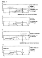
- Fig. 3 typically illustrates the concentration profiles of components in Step (2) of an embodiment of the present invention corresponding to Example 1.
- Fig. 3 (a) is a model diagram illustrating the concentration profiles of components at the time of start of A withdrawal in Stage 2. Specifically, A withdrawal is started at a point of time when a peak assigned to the component A fast in moving velocity reaches the position of withdrawal, and A withdrawal is continued until withdrawal of the portion denoted by "A withdrawal” is completed. Thus, only the optimum zone in the component A concentration profile is withdrawn to complete the operation (1/4 in breadth of Stage 2 in this Figure).
- Fig. 3 (b) is a model diagram illustrating the concentration profiles of the components at a time of perfect circulation in Stage 2. Liquid circulation is continued until the peak portion of the component C slow in moving velocity, which portion is best suited for withdrawal thereof, reaches the position of component C withdrawal (1/2 in breadth of Stage 2 in this Figure).
- Fig. 3 (c) typically illustrates the concentration profiles of the components at the time of start of C withdrawal in Stage 2.
- Fig. 3 (d) is a diagram illustrating the concentration profiles of the components at the time of start of A withdrawal in Step (2) after shift to Stage 3.
- C withdrawal as in Fig. 3 (c) is completed, a state suited for next A withdrawal is established, so that the same operations as in the foregoing Stage 2 are repeated in Stage 3.
- Fig. 4 typically illustrates the concentration profiles of components A, B and C through the circulation system in a conventional method corresponding to Comparative Example 1. Some description will be made while referring to Fig. 4 . Comparison of this description with the foregoing description in connection with Fig. 3 will further facilitate the understanding of features of the present invention.
- Step (2) in the conventional method corresponding to Comparative Example 1 is an ordinary simulated moving bed operation. Because withdrawal of a fraction of the component A fast in moving velocity and a fraction of the component C slow in moving velocity is continued throughout this step, portions containing impurities mixing therein are also withdrawn as the fractions.
- Fig. 4 (a) is a model diagram illustrating the concentration profiles of the components at the time of start of Stage 2. Because 2 fractions are withdrawn throughout Step (2), a peak assigned to the component A fast in moving velocity not sufficiently reaches the position of withdrawing the fraction A, and the component B medium in moving velocity still remains at the position of withdrawing the fraction C. Nevertheless, fraction A withdrawal and fraction C withdrawal are started simultaneously. Withdrawal of the fraction of the component A fast in moving velocity and the fraction of the component C slow in moving velocity is continued throughout Stage 2. In the latter half of this stage, the component B and conditionally further the component C catch up with the portion of the fraction A being withdrawn, but must inevitably be withdrawn.
- Fig. 4 (b) is a model diagram illustrating the concentration profiles of the components at the time of start of Stage 3. Because the top of the component A arrives at the next withdrawal position upon completion of Stage 2, Stage 3 is started. Although the component B remains at the position of withdrawing the fraction C at a point of time of this start, fraction A withdrawal and fraction C withdrawal are started simultaneously.
- the solids-based composition is expressed in terms of areal percentage in high-performance liquid chromatography using a sodium-form ion exchange column and a differential refractometer, and "L" denotes liter(s).
- aqueous solution (solids content: 59.5 wt. %; solids-based composition: 2.6 % oligosaccharides composed of tri- or higher-saccharides, 49.7 % maltose, 47.7 % glucose) prepared as a starting solution material by mixing equal amounts of refined glucose and refined maltose was separated into 3 components with the 3-component separator of Fig. 2 while using demineralized water as eluent.
- AMBERLITE CR-1320 gel type strongly acidic cation exchange resin in Na form for chromatographic separation
- the total amount of packing in the 4 packing bed units was 2,261 ml.
- the tri- or higher-saccharide oligosaccharides recovery of the fraction A was 63.0 %
- the maltose recovery of the fraction B was 97.1 %
- the glucose recovery of the fraction C was 95.2 %.
- Example 2 The same equipment, the same starting solution material and the same packing as used in Example 1 were used to carry out a separation experiment comprising A withdrawal and C withdrawal collectively in the latter half of each stage in each step.
- the tri- or higher-saccharide oligosaccharides recovery of the fraction A was 65.6 %
- the maltose recovery of the fraction B was 96.2 %
- the glucose recovery of the fraction C was 95.2 %.
- Example 2 The same equipment, the same starting solution material and the same packing as used in Example 1 were used to carry out a separation experiment comprising A ⁇ C withdrawal in the first half of each stage.
- the tri- or higher-saccharide oligosaccharides recovery of the fraction A was 63.0 %
- the maltose recovery of the fraction B was 95.2 %
- the glucose recovery of the fraction C was 95.9 %.
- Example 1 The same equipment, the same starting solution material and the same packing as used in Example 1 were used to carry out a separation experiment according to a conventional method (method as disclosed in Japanese Patent Publication No. 24,724/1995 ).
- the tri- or higher-saccharide oligosaccharides recovery of the fraction A was 61.3 %
- the maltose recovery of the fraction B was 90.5 %
- the glucose recovery of the fraction C was 95.0 %.
- Step Time 5.4 min Flow Velocity Starting Solution Material Feed: 13.0 ml/min Fraction A Withdrawal: 5.6 ml/min Fraction B Withdrawal: 39.0 ml/min
- the tri- or higher-saccharide oligosaccharides recovery of the fraction A was 61.7 %
- the maltose recovery of the fraction B was 96.9 %
- the glucose recovery of the fraction C was 95.2 %.
- Example 1 Comparison of Example 1, wherein the process of the present invention was carried out, with Comparative Example 1 is as follows: In Example 1, although the starting solution material feed rate per unit time was high due to the short one cycle time and the amount of used eluent based on the starting solution material was smaller by 4.6 % than that in Comparative Example 1, there could be attained such great improvements in separation performance that the fractions could be separated with respective purities of the principal components higher by 1.9 to 5.0 % than those in Comparative Example 1, and that the fraction B could be separated with a maltose recovery higher by 6.6 % than that in Comparative Example 1. In other words, the process of the present invention is superior to the conventional method with the same number of divisions of the packing bed (number of packing bed units).
- Example 1 In comparison of Example 1 with Comparative Example 2, the respective principal component purities and recoveries of the fractions, substantially comparable to those in Comparative Example 2, could be secured in Example 1 though the starting solution material feed rate per unit time was high due to the short one cycle time.
- the number of divisions of the packing bed (number of packing bed units) in the chromatographic separator could be halved without detriment to separation performance, as compared with that in the conventional method.
- Example 2 Comparison of Example 2 with Example 1 is as follows: In Example 2, oligosaccharides composed of tri- or higher-saccharides as the component A could be prevented from catching up with the fraction C with a tri- or higher-saccharide oligosaccharides content of the fraction C of less than 0.1 %, while maintaining the respective principal component purities of the fractions B and C at levels of those in Example 1 though the starting solution material feed rate per unit time was higher than that in Example 1 due to the shorter one cycle time than that in Example 1 and the amount of used eluent based on the starting solution material was smaller by 1.4 % than that in Example 1.
- Example 3 Comparison of Example 3 with Example 1 is as follows: In Example 3, the amount of glucose as the component C getting into the fraction A due to slowdown thereof could be greatly decreased with an increase in the tri- or higher-saccharide oligosaccharides purity of the fraction A, while maintaining the principal component purity of the fraction B at a level of that in Example 1 though the starting solution material feed rate per unit time was higher than that in Example 1 due to the shorter one cycle time than that in Example 1 and the amount of used eluent based on the starting solution material was smaller by 10.9 % than that in Example 1.
- the separation performance can be improved over those in conventional methods while using 3-component separation simulated moving bed equipment having the same number of packing bed units.
- desired substances can be recovered in high purities and at high recoveries while decreasing the amount of eluent water to be used.
- the process of the present invention which is typically applicable as a method of separating at least 3 components contained in a liquid, is an industrial process for treatment of a large amount of a liquid in particular.
- the usefulness of the process of the present invention is very great particularly in industrial sugar refining facilities for separating and refining various mixtures of saccharides or sugar alcohols while using as packing a strongly acidic cation exchange resin in an alkali metal form or in an alkaline earth metal form.
- sugar refining include separation of sucrose and other useful substances from molasses, separation of glucose, fructose and oligosaccharides from isomerized sugar, separation of components from a liquid mixture containing lactose, lactulose and galactose, separation of components from a liquid mixture containing glucose, sucrose and fructo-oligosaccharides, separation of components from a liquid mixture containing glucose, isomaltose and isomaltodextrin, separation of components from a liquid mixture containing glucose, maltose and maltodextrin, and separation of components from a liquid mixture containing sugar alcohols such as sorbitol and maltitol.
Landscapes
- Chemical & Material Sciences (AREA)
- Life Sciences & Earth Sciences (AREA)
- Sustainable Development (AREA)
- Analytical Chemistry (AREA)
- Chemical Kinetics & Catalysis (AREA)
- Treatment Of Liquids With Adsorbents In General (AREA)
- Steroid Compounds (AREA)
Claims (10)
- Chromatographisches Trennverfahren zum chromatographischen Trennen mit einem chromatographischen Trennmittel, umfassend ein Kreislaufsystem des Fluidströmungsweges, gebildet durch Verbindung einer Vielzahl von Festbetteinheiten zu Endlosreihen, die mit Füllkörpern gefüllt sind, enthaltend als Einheitsabläufe einen Beschickungsarbeitsgang mit Startfluidmaterial, bei dem ein Startfluidmaterial f zugeführt wird, das mindestens 3 Komponenten enthält, klassifiziert als Komponente A, die eine geringe Affinität zum Binden besitzt, und als Komponente B, die eine mittlere Affinität zum Binden besitzt, sowie eine Komponente C, die eine starke Affinität zum Binden im Kreislaufsystem besitzt; einen Fluid desorbierenden Beschickungsarbeitsgang zu Beschicken eines Fluid desorbierenden Mittels in das Kreislaufsystem, und einen Abzugsarbeitsgang für die Fluidfraktion zum Abziehen einer Komponenten A-reichen Fluidfraktion, einer Komponenten B-reichen Fluidfraktion und einer Komponenten C-reichen Fluidfraktion, die voneinander in Richtung der Fluidströmung durch interne Fluidströmung durch das Kreislaufsystem aufgrund ihrer Affinitätsunterschiede aus dem Kreislaufsystem heraus getrennt werden; unter der Voraussetzung, dass die Fluidbeschickungs- und Abzugspositionen voneinander beabstandet sind, entsprechend dahinterliegender Festbetteinheiten des Kreislaufsystems jedes Mal, nachdem jeder Abschnitt der Stufe (1) und Stufe (2) abgeschlossen ist, was über eine Vielzahl von Stufen wiederholt wird, gekennzeichnet durch die folgenden Stufen (1) und (2):Stufe (1): eine Stufe, mindestens den folgenden Arbeitsablauf <1> und den folgenden Arbeitsablauf <2> und/oder <3> umfassend, mit oder ohne weiter umfassend den folgenden Arbeitsablauf <4>; undStufe (2): eine Stufe, mindestens den folgenden Arbeitsablauf <2> und <3> umfassend, mit oder ohne den folgenden Arbeitsablauf <4> umfassend;Arbeitsablauf <1> :ein Arbeitsablauf des Abschaltens des Kreislaufsystems des Fluidströmungsweges an einer Abschaltposition, und Abziehen der gesamten Komponenten B-reichen Fluidfraktion von einer oberstromigen Festbetteinheit, angrenzend an die Abschaltposition oder mindestens einer zweiten oberstromigen Festbetteinheit, während das Startfluidmaterial f zu einer unterstromigen Festbetteinheit angrenzend an die Abschaltposition zugeführt wird und Zuführen des Desorbens D zu einer Festbetteinheit oberstromig der Festbetteinheit, von der die Komponenten B-reiche Fraktion abgezogen wird;Arbeitsabiauf <2> : ein Arbeitablauf des Abziehens eines Teils der Komponenten A- reichen Fraktion im internen Fluid, das durch das Kreislaufsystem zirkuliert, von einer Festbetteinheit, einschließend des optimalen Bereiches in dem Komponenten A Konzentrationsprofil, während das Desorbens D zu einer anderen Festbefiteinheit als die Festbetteinheit zugeführt wird, von der die Komponenten A-reiche Fraktion abgezogen wird;Arbeitsablauf <3> : ein Arbeitsablauf des Abziehens einer Teils der Komponenten C- reichen Fraktion im internen Fluid, das durch das Kreislaufsystem zirkuliert, von einer Festbetteinheit, einschließend der zum Abzug der Komponente C in der Konzentrationsprofilen der Komponenten am besten geeignet ist, während das Desorbens D zur Festbetteinheit, die gerade erwähnt wurde oder einer anderen Festbetteinheit zugeführt wird undArbeitsablauf <4>: ein Arbeitsablauf des Zirkulierens des internen Fluids durch das Kreislaufsystem, weder mit Fluidzuführung noch mit Abzug des Fluids aus dem Kreislaufsystem; unter der Voraussetzung, dass die Arbeitsabfäufe <2> und <3> in jeder Stufe über gegenseitig unabhängige Zeitspannen über teilweise überlappende Zeitspannen oder gleichzeitig in zeitlichem Einvernehmen durchgeführt werden.
- Chromatographisches Trennverfahren nach Anspruch 1, dadurch gekennzeichnet, dass die Stufe (1) die Arbeitsabläufe <1> bis <4> umfasst, während die Stufe (2) die Arbeitsabläufe <2> bis <4> umfasst.
- Chromatographisches Trennverfahren nach Anspruch 1 oder 2, dadurch gekennzeichnet, dass eine Stufe der Stufe (1) und eine Vielzahl von Stufen der Stufe (2) kombiniert damit einen Zyklus der chromatographischen Trennung darstellen, der kontinuierlich über eine Vielzahl von Zyklen wiederholt wird.
- Chromatographisches Trennverfahren nach Anspruch 3, dadurch gekennzeichnet, dass die Anzahl von Stufen in einem Zyklus eine Stufe der Stufe (1) und eine Vielzahl von damit verbundener Stufen der Stufe (2) umfasst, der Anzahl installierter Festbetteinheiten gleicht, die das Kreislaufsystem bilden.
- Chromatographisches Trennverfahren nach irgendeinem der Ansprüche 1-4, dadurch gekennzeichnet, dass die Stufe (1) durchgeführt wird, indem die Arbeitsabläufe <2>, <1> und <3> entweder in dieser Reihenfolge oder in umgekehrter Reihenfolge mit oder ohne den Arbeitsablauf <4> vor jedem Arbeitsablauf durchgeführt werden, während die Stufe (2) durchgeführt wird, indem die Arbeitsabfäufe <2> und <3> entweder in dieser Reihenfolge oder in umgekehrter Reihenfolge mit oder ohne vor jedem Arbeitsablauf den Arbeitsablauf <4> durchzuführen, durchgeführt wird.
- Chromatographisches Trennverfahren nach Anspruch 5, dadurch gekennzeichnet, dass die Stufe (1) durchgeführt wird, indem die Arbeitsabläufe <2>, <4>, <1>, <4> und <3> entweder in dieser Reihenfolge oder in umgekehrter Reihenfolge durchgeführt werden, während die Stufe (2) durchgeführt wird, indem die Arbeitsabläufe <2>, <4> und <3> entweder in dieser Reihenfolge oder in umgekehrter Reihenfolge durchgeführt werden.
- Chromatographisches Trennverfahren nach irgendeinem der Ansprüche 1 bis 4, dadurch gekennzeichnet, dass die Stufe (1) durchgeführt wird, indem die Arbeitsabläufe <4>, <1>, <2> und <3> entweder in dieser Reihenfolge oder in der umgekehrten Reihenfolge, was <2> und <3> anbelangt, mit oder ohne weiter den Arbeitsablauf <4> vor jedem Arbeitsablauf durchzuführen, durchgeführt werden, während die Stufe (2) durchgeführt wird, indem die Arbeitsabläufe <4>, <2> und <3> entweder in dieser Reihenfolge oder in umgekehrter Reihenfolge, was <2> und <3> anbelangt, durchgeführt werden, ohne weiter den Arbeitsablauf <4> vor jedem Arbeitsablauf durchzuführen.
- Chromatographisches Trennverfahren nach Anspruch 7, dadurch gekennzeichnet, dass die Stufe (1) durchgeführt wird, indem die Arbeitsabläufe <4>, <1>, <4>, <2> und < 3 > entweder in dieser Reihenfolge oder in umgekehrter Reihenfolge, was <2> und <3> anbelangt, durchgeführt werden.
- Chromatographisches Trennverfahren nach irgendeinem der Ansprüche 1 bis 4, dadurch gekennzeichnet, dass die Stufe (1) durchgeführt wird, indem die Arbeitsabläufe <2>, <3>, < 1 > und <4> entweder in dieser Reihenfolge oder in umgekehrter Reihenfolge, was <2> und <3> anbelangt, durchgeführt werden, mit oder ohne ferner den Arbeitsablauf <4> vor jedem Arbeitsablauf durchzuführen, während die Stufe (2) durchgeführt wird, indem die Arbeitsabläufe <2>, <3> und <4> entweder in dieser Reihenfolge oder in umgekehrter Reihenfolge , was <2> und <3> anbelangt, durchgeführt werden, mit oder ohne den Arbeitsablauf <4> vor jedem Arbeitsablauf durchzuführen.
- Chromatographisches Trennverfahren nach Anspruch 9, dadurch gekennzeichnet, dass die Stufe (1) durchgeführt wird, indem die Arbeitsabläufe <2>, <3>, <4> <1> und <4> entweder in dieser Reihenfolge oder in umgekehrter Reihenfolge, was <2> und <3> anbelangt, durchgeführt werden.
Applications Claiming Priority (3)
| Application Number | Priority Date | Filing Date | Title |
|---|---|---|---|
| JP15022098A JP3453516B2 (ja) | 1998-05-29 | 1998-05-29 | クロマト分離方法 |
| JP15022098 | 1998-05-29 | ||
| PCT/JP1999/002796 WO1999063339A1 (fr) | 1998-05-29 | 1999-05-27 | Procede de chromatographie |
Publications (3)
| Publication Number | Publication Date |
|---|---|
| EP1003036A1 EP1003036A1 (de) | 2000-05-24 |
| EP1003036A4 EP1003036A4 (de) | 2002-12-18 |
| EP1003036B1 true EP1003036B1 (de) | 2011-07-27 |
Family
ID=15492170
Family Applications (1)
| Application Number | Title | Priority Date | Filing Date |
|---|---|---|---|
| EP99922518A Expired - Lifetime EP1003036B1 (de) | 1998-05-29 | 1999-05-27 | Chromatographieverfahren |
Country Status (6)
| Country | Link |
|---|---|
| US (1) | US6328895B1 (de) |
| EP (1) | EP1003036B1 (de) |
| JP (1) | JP3453516B2 (de) |
| AT (1) | ATE518134T1 (de) |
| AU (1) | AU3954399A (de) |
| WO (1) | WO1999063339A1 (de) |
Families Citing this family (14)
| Publication number | Priority date | Publication date | Assignee | Title |
|---|---|---|---|---|
| JP4176240B2 (ja) * | 1999-07-02 | 2008-11-05 | オルガノ株式会社 | クロマト分離装置 |
| WO2001033210A1 (en) * | 1999-11-02 | 2001-05-10 | Daicel Chemical Industries, Ltd | Simulated moving bed device |
| GB0022713D0 (en) * | 2000-09-15 | 2000-11-01 | Xyrofin Oy | Method for fractionating liquid mixtures |
| WO2003026772A2 (en) * | 2001-09-27 | 2003-04-03 | Purdue Research Foundation | Versatile simulated moving bed systems |
| US20060273013A1 (en) * | 2004-03-01 | 2006-12-07 | Chin Nien-Hwa L | Versatile simulated moving bed systems |
| JP4518477B2 (ja) | 2004-04-05 | 2010-08-04 | オルガノ株式会社 | クロマト分離方法および装置 |
| EP1716900A1 (de) * | 2005-04-29 | 2006-11-02 | Eidgenössische Technische Hochschule Zürich | Verfahren und Vorrichtung zur chromatographischen Reinigung |
| EP1775001A1 (de) | 2005-10-13 | 2007-04-18 | Xendo Holding B.V. | Vorrichtung für chromatographische Trennungen |
| US8920645B2 (en) | 2005-12-07 | 2014-12-30 | Tarpon Biosystems Inc. | Disposable chromatography valves and system |
| WO2007144476A1 (fr) * | 2006-06-16 | 2007-12-21 | Groupe Novasep | Procede de separation sequence multicolonnes |
| WO2008153472A1 (en) | 2007-06-15 | 2008-12-18 | Ge Healthcare Bio-Sciences Ab | Chromatography method |
| CN102271776B (zh) * | 2009-01-06 | 2014-06-11 | 克罗麦肯公司 | 多级分纯化方法和用于所述方法的设备 |
| WO2011046936A1 (en) * | 2009-10-13 | 2011-04-21 | Tarpon Biosystems, Inc. | Conversion of fixed-bed liquid chromatography processes to simulated moving bed processes |
| GB201814213D0 (en) * | 2018-08-31 | 2018-10-17 | Ge Healthcare Bio Sciences Ab | A Connection Device For A Separation System Such As A Chromatography System |
Family Cites Families (14)
| Publication number | Priority date | Publication date | Assignee | Title |
|---|---|---|---|---|
| US3992175A (en) * | 1974-02-11 | 1976-11-16 | Toe Jokhannesovich Klementi | Method of and device for chromatographic separation of fluid mixtures into fractions |
| FR2263802A1 (en) | 1974-03-15 | 1975-10-10 | Sp K Bjur | Chromatographic sepn. of fluid mixts. - by several sepn. columns connected in series in a closed loop |
| JPH0746097B2 (ja) * | 1988-05-17 | 1995-05-17 | 三菱化成エンジニアリング株式会社 | クロマト分離法 |
| US5198120A (en) * | 1989-12-26 | 1993-03-30 | Japan Organo Co., Ltd. | Process for fractional separation of multi-component fluid mixture |
| JPH0724724B2 (ja) | 1989-12-26 | 1995-03-22 | オルガノ株式会社 | 多成分系の分離方法および装置 |
| JP2962594B2 (ja) * | 1991-06-12 | 1999-10-12 | オルガノ株式会社 | 複数成分の分離方法 |
| JP2965747B2 (ja) | 1991-06-24 | 1999-10-18 | オルガノ株式会社 | 多成分系の分離方法および装置 |
| JP3010816B2 (ja) * | 1991-08-22 | 2000-02-21 | ダイセル化学工業株式会社 | 光学分割における光学異性体と溶媒との回収方法、溶媒の循環使用方法、および光学異性体の再利用方法 |
| US5498752A (en) * | 1991-08-22 | 1996-03-12 | Daicel Chemical Industries, Ltd. | Process for recovering optical isomers and solvent, process for using solvent by circulation and process for reusing optical isomers in optical resolution |
| US5770088A (en) * | 1992-06-30 | 1998-06-23 | Daicel Chemical Industries, Ltd. | Simulated moving bed chromatographic separation process |
| JP3070890B2 (ja) * | 1993-02-12 | 2000-07-31 | オルガノ株式会社 | 澱粉糖の製造方法 |
| JP3117596B2 (ja) | 1993-12-29 | 2000-12-18 | オルガノ株式会社 | 3分子以上の単糖類分子がグリコシド結合してなる糖類の製造方法 |
| US5470464A (en) * | 1994-04-06 | 1995-11-28 | Uop | Small scale simulated moving bed separation apparatus and process |
| JP3786990B2 (ja) | 1995-11-08 | 2006-06-21 | 東和化成工業株式会社 | マルチトールの精製方法 |
-
1998
- 1998-05-29 JP JP15022098A patent/JP3453516B2/ja not_active Expired - Lifetime
-
1999
- 1999-05-25 AU AU39543/99A patent/AU3954399A/en not_active Abandoned
- 1999-05-27 WO PCT/JP1999/002796 patent/WO1999063339A1/ja not_active Ceased
- 1999-05-27 US US09/463,688 patent/US6328895B1/en not_active Expired - Lifetime
- 1999-05-27 AT AT99922518T patent/ATE518134T1/de not_active IP Right Cessation
- 1999-05-27 EP EP99922518A patent/EP1003036B1/de not_active Expired - Lifetime
Also Published As
| Publication number | Publication date |
|---|---|
| EP1003036A1 (de) | 2000-05-24 |
| ATE518134T1 (de) | 2011-08-15 |
| US6328895B1 (en) | 2001-12-11 |
| WO1999063339A1 (fr) | 1999-12-09 |
| EP1003036A4 (de) | 2002-12-18 |
| JPH11344481A (ja) | 1999-12-14 |
| JP3453516B2 (ja) | 2003-10-06 |
| AU3954399A (en) | 1999-12-20 |
Similar Documents
| Publication | Publication Date | Title |
|---|---|---|
| EP1003036B1 (de) | Chromatographieverfahren | |
| EP0279946B1 (de) | Methode für chromatographische Trennung | |
| EP2401047B1 (de) | Separationsverfahren | |
| EP0342629B1 (de) | Chromatographische Trennungsmethode | |
| US6482268B2 (en) | Fractionation method for sucrose-containing solutions | |
| EP2552562B1 (de) | Separationsverfahren | |
| EP0966425B1 (de) | Verfahren zur gewinnung von betain | |
| JP2962594B2 (ja) | 複数成分の分離方法 | |
| JP2002143605A (ja) | クロマト分離方法 | |
| EP1349631B1 (de) | Verfahren zur fraktionierung flüssiger mischungen | |
| US6409922B1 (en) | Chromatographic separation process and chromatographic separator | |
| US6331250B1 (en) | Method and equipment for chromatographic separation | |
| US6224683B1 (en) | Process for demineralizing a sugar solution | |
| CA2298554C (en) | Chromatographic separation process | |
| JPH06170112A (ja) | クロマト分離法 | |
| KR102491223B1 (ko) | 크로마토 분리 방법 및 크로마토 분리 장치 | |
| JPH05204A (ja) | 多成分系の分離方法および装置 | |
| JPH04227804A (ja) | 多成分系の分離方法および装置 | |
| JPH04363102A (ja) | 複数成分の分離方法 |
Legal Events
| Date | Code | Title | Description |
|---|---|---|---|
| PUAI | Public reference made under article 153(3) epc to a published international application that has entered the european phase |
Free format text: ORIGINAL CODE: 0009012 |
|
| 17P | Request for examination filed |
Effective date: 20000209 |
|
| AK | Designated contracting states |
Kind code of ref document: A1 Designated state(s): AT BE CH CY DE DK ES FI FR GB GR IE IT LI LU MC NL PT SE |
|
| A4 | Supplementary search report drawn up and despatched |
Effective date: 20021107 |
|
| AK | Designated contracting states |
Kind code of ref document: A4 Designated state(s): AT BE CH CY DE DK ES FI FR GB GR IE IT LI LU MC NL PT SE |
|
| RIC1 | Information provided on ipc code assigned before grant |
Free format text: 7G 01N 30/46 A, 7B 01D 15/00 B, 7B 01D 15/02 B |
|
| 17Q | First examination report despatched |
Effective date: 20071213 |
|
| GRAP | Despatch of communication of intention to grant a patent |
Free format text: ORIGINAL CODE: EPIDOSNIGR1 |
|
| GRAS | Grant fee paid |
Free format text: ORIGINAL CODE: EPIDOSNIGR3 |
|
| GRAA | (expected) grant |
Free format text: ORIGINAL CODE: 0009210 |
|
| AK | Designated contracting states |
Kind code of ref document: B1 Designated state(s): AT BE CH CY DE DK ES FI FR GB GR IE IT LI LU MC NL PT SE |
|
| REG | Reference to a national code |
Ref country code: GB Ref legal event code: FG4D |
|
| REG | Reference to a national code |
Ref country code: CH Ref legal event code: EP |
|
| REG | Reference to a national code |
Ref country code: DE Ref legal event code: R096 Ref document number: 69943595 Country of ref document: DE Effective date: 20110922 |
|
| REG | Reference to a national code |
Ref country code: NL Ref legal event code: VDEP Effective date: 20110727 |
|
| REG | Reference to a national code |
Ref country code: AT Ref legal event code: MK05 Ref document number: 518134 Country of ref document: AT Kind code of ref document: T Effective date: 20110727 |
|
| PG25 | Lapsed in a contracting state [announced via postgrant information from national office to epo] |
Ref country code: NL Free format text: LAPSE BECAUSE OF FAILURE TO SUBMIT A TRANSLATION OF THE DESCRIPTION OR TO PAY THE FEE WITHIN THE PRESCRIBED TIME-LIMIT Effective date: 20110727 Ref country code: PT Free format text: LAPSE BECAUSE OF FAILURE TO SUBMIT A TRANSLATION OF THE DESCRIPTION OR TO PAY THE FEE WITHIN THE PRESCRIBED TIME-LIMIT Effective date: 20111128 Ref country code: SE Free format text: LAPSE BECAUSE OF FAILURE TO SUBMIT A TRANSLATION OF THE DESCRIPTION OR TO PAY THE FEE WITHIN THE PRESCRIBED TIME-LIMIT Effective date: 20110727 Ref country code: BE Free format text: LAPSE BECAUSE OF FAILURE TO SUBMIT A TRANSLATION OF THE DESCRIPTION OR TO PAY THE FEE WITHIN THE PRESCRIBED TIME-LIMIT Effective date: 20110727 Ref country code: FI Free format text: LAPSE BECAUSE OF FAILURE TO SUBMIT A TRANSLATION OF THE DESCRIPTION OR TO PAY THE FEE WITHIN THE PRESCRIBED TIME-LIMIT Effective date: 20110727 |
|
| PG25 | Lapsed in a contracting state [announced via postgrant information from national office to epo] |
Ref country code: GR Free format text: LAPSE BECAUSE OF FAILURE TO SUBMIT A TRANSLATION OF THE DESCRIPTION OR TO PAY THE FEE WITHIN THE PRESCRIBED TIME-LIMIT Effective date: 20111028 Ref country code: AT Free format text: LAPSE BECAUSE OF FAILURE TO SUBMIT A TRANSLATION OF THE DESCRIPTION OR TO PAY THE FEE WITHIN THE PRESCRIBED TIME-LIMIT Effective date: 20110727 Ref country code: CY Free format text: LAPSE BECAUSE OF FAILURE TO SUBMIT A TRANSLATION OF THE DESCRIPTION OR TO PAY THE FEE WITHIN THE PRESCRIBED TIME-LIMIT Effective date: 20110727 |
|
| PG25 | Lapsed in a contracting state [announced via postgrant information from national office to epo] |
Ref country code: IT Free format text: LAPSE BECAUSE OF FAILURE TO SUBMIT A TRANSLATION OF THE DESCRIPTION OR TO PAY THE FEE WITHIN THE PRESCRIBED TIME-LIMIT Effective date: 20110727 |
|
| PLBE | No opposition filed within time limit |
Free format text: ORIGINAL CODE: 0009261 |
|
| STAA | Information on the status of an ep patent application or granted ep patent |
Free format text: STATUS: NO OPPOSITION FILED WITHIN TIME LIMIT |
|
| PG25 | Lapsed in a contracting state [announced via postgrant information from national office to epo] |
Ref country code: DK Free format text: LAPSE BECAUSE OF FAILURE TO SUBMIT A TRANSLATION OF THE DESCRIPTION OR TO PAY THE FEE WITHIN THE PRESCRIBED TIME-LIMIT Effective date: 20110727 |
|
| 26N | No opposition filed |
Effective date: 20120502 |
|
| REG | Reference to a national code |
Ref country code: DE Ref legal event code: R097 Ref document number: 69943595 Country of ref document: DE Effective date: 20120502 |
|
| PG25 | Lapsed in a contracting state [announced via postgrant information from national office to epo] |
Ref country code: MC Free format text: LAPSE BECAUSE OF NON-PAYMENT OF DUE FEES Effective date: 20120531 |
|
| REG | Reference to a national code |
Ref country code: CH Ref legal event code: PL |
|
| PG25 | Lapsed in a contracting state [announced via postgrant information from national office to epo] |
Ref country code: CH Free format text: LAPSE BECAUSE OF NON-PAYMENT OF DUE FEES Effective date: 20120531 Ref country code: LI Free format text: LAPSE BECAUSE OF NON-PAYMENT OF DUE FEES Effective date: 20120531 |
|
| REG | Reference to a national code |
Ref country code: IE Ref legal event code: MM4A |
|
| PG25 | Lapsed in a contracting state [announced via postgrant information from national office to epo] |
Ref country code: ES Free format text: LAPSE BECAUSE OF FAILURE TO SUBMIT A TRANSLATION OF THE DESCRIPTION OR TO PAY THE FEE WITHIN THE PRESCRIBED TIME-LIMIT Effective date: 20111107 Ref country code: IE Free format text: LAPSE BECAUSE OF NON-PAYMENT OF DUE FEES Effective date: 20120527 |
|
| PGFP | Annual fee paid to national office [announced via postgrant information from national office to epo] |
Ref country code: DE Payment date: 20130522 Year of fee payment: 15 |
|
| PG25 | Lapsed in a contracting state [announced via postgrant information from national office to epo] |
Ref country code: LU Free format text: LAPSE BECAUSE OF NON-PAYMENT OF DUE FEES Effective date: 20120527 |
|
| REG | Reference to a national code |
Ref country code: DE Ref legal event code: R119 Ref document number: 69943595 Country of ref document: DE |
|
| REG | Reference to a national code |
Ref country code: DE Ref legal event code: R119 Ref document number: 69943595 Country of ref document: DE Effective date: 20141202 |
|
| PG25 | Lapsed in a contracting state [announced via postgrant information from national office to epo] |
Ref country code: DE Free format text: LAPSE BECAUSE OF NON-PAYMENT OF DUE FEES Effective date: 20141202 |
|
| REG | Reference to a national code |
Ref country code: FR Ref legal event code: PLFP Year of fee payment: 18 |
|
| REG | Reference to a national code |
Ref country code: FR Ref legal event code: PLFP Year of fee payment: 19 |
|
| REG | Reference to a national code |
Ref country code: FR Ref legal event code: PLFP Year of fee payment: 20 |
|
| PGFP | Annual fee paid to national office [announced via postgrant information from national office to epo] |
Ref country code: GB Payment date: 20180329 Year of fee payment: 20 |
|
| PGFP | Annual fee paid to national office [announced via postgrant information from national office to epo] |
Ref country code: FR Payment date: 20180412 Year of fee payment: 20 |
|
| REG | Reference to a national code |
Ref country code: GB Ref legal event code: PE20 Expiry date: 20190526 |
|
| PG25 | Lapsed in a contracting state [announced via postgrant information from national office to epo] |
Ref country code: GB Free format text: LAPSE BECAUSE OF EXPIRATION OF PROTECTION Effective date: 20190526 |