EP1003049A2 - Sender zur Störsignalwiederholung und Gehäuse für denselben - Google Patents
Sender zur Störsignalwiederholung und Gehäuse für denselben Download PDFInfo
- Publication number
- EP1003049A2 EP1003049A2 EP99850162A EP99850162A EP1003049A2 EP 1003049 A2 EP1003049 A2 EP 1003049A2 EP 99850162 A EP99850162 A EP 99850162A EP 99850162 A EP99850162 A EP 99850162A EP 1003049 A2 EP1003049 A2 EP 1003049A2
- Authority
- EP
- European Patent Office
- Prior art keywords
- antenna
- transmitter
- antennas
- receiver
- repeater jamming
- Prior art date
- Legal status (The legal status is an assumption and is not a legal conclusion. Google has not performed a legal analysis and makes no representation as to the accuracy of the status listed.)
- Granted
Links
Images


Classifications
-
- H—ELECTRICITY
- H04—ELECTRIC COMMUNICATION TECHNIQUE
- H04K—SECRET COMMUNICATION; JAMMING OF COMMUNICATION
- H04K3/00—Jamming of communication; Counter-measures
- H04K3/20—Countermeasures against jamming
- H04K3/28—Countermeasures against jamming with jamming and anti-jamming mechanisms both included in a same device or system, e.g. wherein anti-jamming includes prevention of undesired self-jamming resulting from jamming
-
- G—PHYSICS
- G01—MEASURING; TESTING
- G01S—RADIO DIRECTION-FINDING; RADIO NAVIGATION; DETERMINING DISTANCE OR VELOCITY BY USE OF RADIO WAVES; LOCATING OR PRESENCE-DETECTING BY USE OF THE REFLECTION OR RERADIATION OF RADIO WAVES; ANALOGOUS ARRANGEMENTS USING OTHER WAVES
- G01S7/00—Details of systems according to groups G01S13/00, G01S15/00, G01S17/00
- G01S7/02—Details of systems according to groups G01S13/00, G01S15/00, G01S17/00 of systems according to group G01S13/00
- G01S7/38—Jamming means, e.g. producing false echoes
-
- H—ELECTRICITY
- H04—ELECTRIC COMMUNICATION TECHNIQUE
- H04K—SECRET COMMUNICATION; JAMMING OF COMMUNICATION
- H04K3/00—Jamming of communication; Counter-measures
- H04K3/40—Jamming having variable characteristics
- H04K3/43—Jamming having variable characteristics characterized by the control of the jamming power, signal-to-noise ratio or geographic coverage area
-
- H—ELECTRICITY
- H04—ELECTRIC COMMUNICATION TECHNIQUE
- H04K—SECRET COMMUNICATION; JAMMING OF COMMUNICATION
- H04K3/00—Jamming of communication; Counter-measures
- H04K3/40—Jamming having variable characteristics
- H04K3/45—Jamming having variable characteristics characterized by including monitoring of the target or target signal, e.g. in reactive jammers or follower jammers for example by means of an alternation of jamming phases and monitoring phases, called "look-through mode"
-
- H—ELECTRICITY
- H04—ELECTRIC COMMUNICATION TECHNIQUE
- H04K—SECRET COMMUNICATION; JAMMING OF COMMUNICATION
- H04K3/00—Jamming of communication; Counter-measures
- H04K3/40—Jamming having variable characteristics
- H04K3/46—Jamming having variable characteristics characterized in that the jamming signal is produced by retransmitting a received signal, after delay or processing
-
- H—ELECTRICITY
- H04—ELECTRIC COMMUNICATION TECHNIQUE
- H04K—SECRET COMMUNICATION; JAMMING OF COMMUNICATION
- H04K3/00—Jamming of communication; Counter-measures
- H04K3/60—Jamming involving special techniques
- H04K3/65—Jamming involving special techniques using deceptive jamming or spoofing, e.g. transmission of false signals for premature triggering of RCIED, for forced connection or disconnection to/from a network or for generation of dummy target signal
-
- H—ELECTRICITY
- H04—ELECTRIC COMMUNICATION TECHNIQUE
- H04K—SECRET COMMUNICATION; JAMMING OF COMMUNICATION
- H04K2203/00—Jamming of communication; Countermeasures
- H04K2203/10—Jamming or countermeasure used for a particular application
- H04K2203/22—Jamming or countermeasure used for a particular application for communication related to vehicles
-
- H—ELECTRICITY
- H04—ELECTRIC COMMUNICATION TECHNIQUE
- H04K—SECRET COMMUNICATION; JAMMING OF COMMUNICATION
- H04K2203/00—Jamming of communication; Countermeasures
- H04K2203/30—Jamming or countermeasure characterized by the infrastructure components
- H04K2203/32—Jamming or countermeasure characterized by the infrastructure components including a particular configuration of antennas
Definitions
- This invention concerns a broad-band repeater jamming transmitter comprising receiver antenna, amplifier and transmitter antenna for receiving, amplifying and transmitting signals, which repeater jamming transmitter comprises a connection arrangement with antiphase connection for maintaining isolation between the receiver antenna and the transmitter antenna in the angular area where reception and transmission take place simultaneously.
- the invention also concerns a casing arrangement with repeater jamming transmitter.
- the repeater jamming transmitter is designed with two receiver antennas, whereby the received signal on one receiver antenna separate from the antenna function is phase-displaced by 180° before it is combined with the signal from the second receiver antenna in a power combiner.
- the arrangement with two receiver antennas and separate antiphase connection makes the jamming transmitter large and heavy.
- Repeater jamming transmitters generate an amplified signal in the field of radar by receiving a radar signal, amplifying it in an amplifier and sending the signal out again.
- the amplified signal creates a mock target for the radar which the radar perceives as having a greater target area the higher the amplification which can be achieved. It is therefore important to attain a high amplification.
- the isolation between the transmitter antenna and the receiver antenna can be increased by increasing the distance between the antennas and thereby permitting an increase in the amplification. It is, however, desirable in connection for example with aircraft, to have a repeater jamming transmitter which has as small dimensions as possible. A mock target is thus created with favourable characteristics. At the same time the repeater jamming transmitter takes up less space and can be made lighter, which makes it particularly suitable for installation as airborne equipment. The compact format can also help to keep down the manufacturing costs, which is of particular value as the repeater jamming transmitter is completely separated from the aircraft after use.
- the aim of this invention is to achieve a repeater jamming transmitter with small dimensions which can provide high amplification and has the other benefits of repeater jamming transmitters with small dimensions mentioned above.
- the aim of the invention is achieved by a repeater jamming transmitter characterized in that the repeater jamming transmitter being designed to be ejected out of an aircraft and to operate at a distance from the aircraft in motion, that the receiver antenna and the transmitter antenna each comprise at least one pair of antennas and that the connection arrangement for maintaining the isolation between the receiver antenna and the transmitter antenna comprises an antiphase connection arranged directly in the pair of antennas of the receiver antenna and/or the transmitter antenna.
- the transmitter antenna and the receiver antenna can thereby each comprise one or more pairs of antennas and according to a suitable embodiment it is proposed that the transmitter antenna and receiver antenna comprise two pairs of antennas turned in relation to each other with the aim of receiving and transmitting in two preferably orthogonal polarisations turned in relation to each other.
- the pairs of antennas of the receiver antenna and the transmitter antenna can comprise a first and a second outer conductor designed with antenna ribs, and a central conductor.
- a preferred embodiment in order to achieve an antiphase connection in a pair of antennas one antenna tip is connected between the first outer conductor and the central conductor and the second antenna tip is connected between the second outer conductor and the central conductor.
- the direction of the antenna ribs in one antenna is arranged in a reversed direction in relation to the second antenna.
- the antiphase connection improves the isolation between the transmitter antenna and the receiver antenna.
- the antiphase connection is carried out in connection with the input of the amplifier.
- This places large demands on accuracy in installation as electrical wavelengths from both antennas in the pair of antennas must be very accurately matched. Temperature increases can cause the wavelengths to change, with reduced isolation as a result.
- This solution is also cheaper than making the antiphase connection in association with the amplifier.
- the pair of antennas in antiphase creates a null depth in the normal direction of the pairs of antennas. This null depth coincides with the beam maximum of the pair of antennas connected in the same phase. As the target area is the product of the antenna gain, the value of this beam maximum will decrease.
- the antenna planes of the receiver antennas are to be turned in relation to the antenna planes of the transmitter antennas. In particular it is proposed that the turning between the antenna planes of the receiver antennas and the antenna planes of the transmitter antennas is to be of the order of 20°.
- the null depth can be moved to a direction where it does less harm.
- the average target area is increased defined over a conical cross section, which is valuable in many fields of application associated with repeater jamming transmitters.
- the repeater jamming transmitter is characterized in that the means of automatic regulation of the amplification comprises an amplification control, power meter and switch arranged between the receiver antenna and the transmitter antenna, whereby the reduced power with the switch open in comparison to with the switch closed indicates self-oscillation.
- the repeater jamming transmitter can be housed in a casing together with a cable brake attached to the bottom part of the casing.
- This casing arrangement has obvious advantages as far as handling is concerned.
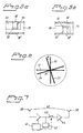
- Figure 1 shows an aircraft 1 which tows a repeater jamming transmitter 2 on a cable 3.
- the repeater jamming transmitter is stored during normal flight in some form of accommodation in connection with the aircraft.
- the space for droppable ammunition for example for IR flares or strips, can be used to house the repeater jamming transmitter.
- the repeater jamming transmitter 2 is housed in a casing 4 together with a cable brake 5.
- This embodiment means that the repeater jamming transmitter can easily be housed in compartments dimensioned for droppable ammunition.
- the control of the repeater jamming transmitter from the aircraft can then be carried out via a connection device (not shown) in the bottom plate 6 of the casing 4.
- the repeater jamming transmitter 2 shown diagrammatically in Figure 3 has a front antenna 7 and a rear antenna 8 housed in a casing 9.
- One of the antennas 7 and 8 acts as a transmitter antenna and the other as a receiver antenna.
- the front antenna 7 acts as transmitter antenna and the rear antenna 8 as a receiver antenna.
- An electronics part 10 with amplifier and control circuits is connected between the receiver antenna 8 and the transmitter antenna 7.
- a battery 11 in the front part of the casing.
- the repeater jamming transmitter suitable flying properties it is equipped with extending fins 12, 13 and 14 shown in the extended position.
- the transmitter antenna 7 and the receiver antenna 8 are both shown diagrammatically as a pair of antennas 7', 7'' and 8',8'' respectively in a common plane. Between the transmitter antenna and receiver antenna means, not shown, can be arranged to prevent internal leakage between the transmitter antenna and the receiver antenna, for example some form of metal screen.
- the design of the antennas will be discussed in greater detail below with reference to Figures 4, 5a and 5b.
- the antenna configuration for the repeater jamming transmitter shown in Figure 4 comprises a front antenna 15 with two pairs of antennas 16, 17 with two antenna units each, 16',16'' and 17',17'' respectively in a common plane.
- the antenna units are constructed with a conductive pattern 18 arranged on each side of an isolating layer 19 so that the complete conductive pattern creates a principally symmetrical form.
- a central conductor enclosed by the isolating layer runs from a supply point 20 to the tip 21 of the antenna unit.
- the central conductor is connected to the conductive pattern 18 on one side of the isolating layer 19 and in Figure 4 the side where the isolating layer 19 has a recess 29.
- the antenna configuration comprises in addition a rear antenna 22 constructed in a similar way as the front antenna 15.
- the antenna units have in addition a conductive pattern 25 on each side of an isolating layer 26.
- a central conductor runs within the isolating layer from a connection point 27 to the tip 28 of the antenna unit where the conductor is connected to the conductive pattern on one side of the conductive pattern 25. Specifically in the figure the central conductor is connected to the pattern 25 on the side where the isolating layer has a recess 30.
- the conductive patterns shown for the pairs of antennas 16 and 23 are compared it can be found that the beams from the antenna units in the antenna pair 23 of the rear antenna will interact in the longitudinal direction of the axle 31, while the beams from the antenna units in the antenna pair 16 of the front antenna will counteract each other in the longitudinal direction of the axle 31. An antiphase connection is then brought about in the front antenna which improves the isolation between the front and rear antennas.
- FIG. 5a An alternative way of bringing about antiphase connection is shown diagrammatically in Figures 5a and 5b.
- the front antenna 15 according to Figure 4 has been given the same conductive pattern configuration as the rear antenna 22.
- the ability is used instead to vary the connection of the central conductor 32.
- a recess 33 is used to connect the central conductor 32 with the pattern 18' on one side of the isolating layer 19 in a pair of antennas via a conductive connection 35.
- a recess 36 is arranged to connect the central conductor 32 with the pattern 18'' on the other side of the isolating layer 19 in the same pair of antennas via a conductive connector 37.
- the antennas 15 and 22 can be connected to the electronics part 10 in many different ways, partly dependent upon to what extent it is wished to control the antennas.
- the embodiments described with reference to Figure 4 and Figures 5a and 5b can easily be connected using two coaxial cables to each antenna 15, 22 from the electronics part 10. In this way each pair of antennas 16,17,23 and 24 has a separate connection.
- the inner conductors of the coaxial cable are connected to the supply point 20 for the central conductor 32 of the pair of antennas 16, while the screen is connected to the conductive pattern 18,18',18''.
- the conductive pattern 18,18',18'' then acts as the earth plane of the pair of antennas.
- Corresponding connections can be made to other pairs of antennas involved.
- Alternative methods of supply are, for example, to supply several pairs of antennas jointly or to supply antenna units individually.
- the antenna configuration shown in Figure 4 has the characteristics that the pair of antennas 23,24 in the rear antenna 22 are turned somewhat in relation to the pairs of antennas 16,17 in the front antenna 15 with respect to the axle 31.
- Figure 6 which shows the configuration diagrammatically with the axle 31 perpendicular to the plane of the drawing.
- the turning which is indicated by ⁇ in Figure 6 can suitably have a value of the order of 20°.
- Figure 7 shows an example of how the amplification regulation can be carried out in order to achieve the highest possible setting of the amplification in each individual operating instance.
- an amplification control 41 a power meter 42 and a switch 43 are connected in the way shown.
- the transmitter antenna 38 is supplied via an amplifier 44.
- the power meter is arranged to measure the power received with an open and closed switch 43 and compare these measurements. If the power meter detects the same power with the switch open and closed, it means that it is an external radar signal which has been amplified. On the other cane if the power disappears when the switch is opened this indicates self-oscillation.
- the maximal amplification and hence target area can be set for the operating instance concerned.
Landscapes
- Engineering & Computer Science (AREA)
- Computer Networks & Wireless Communication (AREA)
- Signal Processing (AREA)
- Radar, Positioning & Navigation (AREA)
- Remote Sensing (AREA)
- Physics & Mathematics (AREA)
- General Physics & Mathematics (AREA)
- Radio Relay Systems (AREA)
- Variable-Direction Aerials And Aerial Arrays (AREA)
Applications Claiming Priority (2)
| Application Number | Priority Date | Filing Date | Title |
|---|---|---|---|
| SE9803935 | 1998-11-18 | ||
| SE9803935A SE520836C3 (sv) | 1998-11-18 | 1998-11-18 | Repeterstörsändare samt hylsarrangemang för densamma |
Publications (3)
| Publication Number | Publication Date |
|---|---|
| EP1003049A2 true EP1003049A2 (de) | 2000-05-24 |
| EP1003049A3 EP1003049A3 (de) | 2003-01-22 |
| EP1003049B1 EP1003049B1 (de) | 2005-02-23 |
Family
ID=20413325
Family Applications (1)
| Application Number | Title | Priority Date | Filing Date |
|---|---|---|---|
| EP99850162A Expired - Lifetime EP1003049B1 (de) | 1998-11-18 | 1999-11-03 | Sender zur Störsignalwiederholung und Gehäuse für denselben |
Country Status (5)
| Country | Link |
|---|---|
| US (1) | US6384765B1 (de) |
| EP (1) | EP1003049B1 (de) |
| DE (1) | DE69923822T2 (de) |
| IL (1) | IL132829A0 (de) |
| SE (1) | SE520836C3 (de) |
Cited By (8)
| Publication number | Priority date | Publication date | Assignee | Title |
|---|---|---|---|---|
| RU2319167C1 (ru) * | 2006-06-29 | 2008-03-10 | Федеральное Государственное Образовательное Учреждение Высшего Профессионального Образования "Южный Федеральный Университет" | Устройство адаптивного управления спектральными характеристиками рассеяния радиолокационного объекта |
| RU2326399C1 (ru) * | 2007-02-08 | 2008-06-10 | Федеральное государственное учреждение "Федеральный государственный научно-исследовательский испытательный центр радиоэлектронной борьбы и оценки эффективности снижения заметности" Министерства обороны Российской Федерации | Способ имитации многопозиционной радиоэлектронной обстановки |
| RU2349926C1 (ru) * | 2007-08-13 | 2009-03-20 | Федеральное государственное унитарное предприятие "Центральный научно-исследовательский радиотехнический институт имени академика А.И. Берга" | Цифровое устройство создания активных помех |
| RU2434241C1 (ru) * | 2010-06-03 | 2011-11-20 | Игорь Николаевич Воробьёв | Станция помех |
| RU2554092C1 (ru) * | 2014-01-09 | 2015-06-27 | Акционерное общество "НИИ измерительных приборов-Новосибирский завод имени Коминтерна" /АО "НПО НИИИП-НЗиК"/ | Способ обзора пространства (варианты) |
| RU2564130C1 (ru) * | 2014-07-04 | 2015-09-27 | Акционерное общество "Федеральный научно-производственный центр "Нижегородский научно-исследовательский институт радиотехники" (АО "ФНПЦ "ННИИРТ") | Способ и устройство обзора пространства в рлс |
| RU2624247C1 (ru) * | 2016-07-19 | 2017-07-03 | АО "Научно-технический центр радиоэлектронной борьбы" | Способ радиоэлектронного подавления приемных устройств потребителей глобальных навигационных спутниковых систем |
| RU2632219C1 (ru) * | 2016-07-07 | 2017-10-03 | ФЕДЕРАЛЬНОЕ ГОСУДАРСТВЕННОЕ КАЗЕННОЕ ВОЕННОЕ ОБРАЗОВАТЕЛЬНОЕ УЧРЕЖДЕНИЕ ВЫСШЕГО ОБРАЗОВАНИЯ "Военная академия Ракетных войск стратегического назначения имени Петра Великого" МИНИСТЕРСТВА ОБОРОНЫ РОССИЙСКОЙ ФЕДЕРАЦИИ | Способ активной радиомаскировки радиоэлектронных средств станциями активных помех и устройство для его реализации |
Families Citing this family (24)
| Publication number | Priority date | Publication date | Assignee | Title |
|---|---|---|---|---|
| SE522506C2 (sv) * | 2002-06-19 | 2004-02-10 | Totalfoersvarets Forskningsins | Släpstörsändare och sätt att förbättra en sådan |
| DE60322541D1 (de) * | 2002-06-21 | 2008-09-11 | Qualcomm Inc | Zwischenverstärker für drahtlose lokale netzwerke |
| US8885688B2 (en) | 2002-10-01 | 2014-11-11 | Qualcomm Incorporated | Control message management in physical layer repeater |
| AU2003274992A1 (en) * | 2002-10-11 | 2004-05-04 | Widefi, Inc. | Reducing loop effects in a wireless local area network repeater |
| KR20050071571A (ko) * | 2002-10-15 | 2005-07-07 | 위데피, 인코포레이티드 | 네트워크 커버리지 확장을 위해 자동 이득 제어를 이용하는wlan 중계기 |
| US8078100B2 (en) | 2002-10-15 | 2011-12-13 | Qualcomm Incorporated | Physical layer repeater with discrete time filter for all-digital detection and delay generation |
| US7230935B2 (en) * | 2002-10-24 | 2007-06-12 | Widefi, Inc. | Physical layer repeater with selective use of higher layer functions based on network operating conditions |
| EP1568167A4 (de) | 2002-11-15 | 2010-06-16 | Qualcomm Inc | Drahtloser zwischenverstärker für lokale netzwerke mit detektion |
| AU2003300938A1 (en) | 2002-12-16 | 2004-07-29 | Widefi, Inc. | Improved wireless network repeater |
| US8027642B2 (en) * | 2004-04-06 | 2011-09-27 | Qualcomm Incorporated | Transmission canceller for wireless local area network |
| KR101291850B1 (ko) * | 2004-05-13 | 2013-07-31 | 퀄컴 인코포레이티드 | 업링크 및 다운링크 동기화를 위해 다운링크를 검출하는 비-주파수 변환 리피터 |
| US7187904B2 (en) | 2004-06-03 | 2007-03-06 | Widefi, Inc. | Frequency translating repeater with low cost high performance local oscillator architecture |
| US8059727B2 (en) | 2005-01-28 | 2011-11-15 | Qualcomm Incorporated | Physical layer repeater configuration for increasing MIMO performance |
| FR2882441B1 (fr) * | 2005-02-23 | 2007-04-20 | Sagem | Dispositif de contre-mesure et de poursuite d'une menace avec dispositif de retard optique |
| FR2882440B1 (fr) * | 2005-02-23 | 2007-04-20 | Sagem | Dispositif de contre-mesure et de poursuite d'une menace sous la forme d'un missile a autodirecteur |
| DE102005035251A1 (de) * | 2005-07-25 | 2007-02-01 | Rheinmetall Waffe Munition Gmbh | Verfahren und Vorrichtung zur Täuschung infrarot-, radar- als auch Dual Mode- gelenkter Flugkörper |
| US7400287B2 (en) * | 2006-02-17 | 2008-07-15 | Honeywell International Inc. | Smart chaff |
| JP5107997B2 (ja) * | 2006-03-31 | 2012-12-26 | クゥアルコム・インコーポレイテッド | WiMAXシステム内の動作のための機能強化した物理層中継器 |
| JP5199261B2 (ja) | 2006-09-21 | 2013-05-15 | クゥアルコム・インコーポレイテッド | リピータの間の振動を緩和するための方法および装置 |
| KR20090074812A (ko) | 2006-10-26 | 2009-07-07 | 퀄컴 인코포레이티드 | 빔 형성기를 이용한 다중 입력 다중 출력을 위한 중계기 기술 |
| US8537048B2 (en) * | 2008-09-26 | 2013-09-17 | The Boeing Company | Active chaff |
| US9290269B2 (en) | 2013-03-15 | 2016-03-22 | CyPhy Works, Inc. | Spooler for unmanned aerial vehicle system |
| US11789117B2 (en) * | 2018-09-27 | 2023-10-17 | Ay Dee Kay Llc | Active reflector with oscillation inhibition |
| US20210382139A1 (en) * | 2020-06-05 | 2021-12-09 | University Of Pretoria | Phase-conjugating retrodirective cross-eye radar jamming |
Family Cites Families (17)
| Publication number | Priority date | Publication date | Assignee | Title |
|---|---|---|---|---|
| US2270965A (en) * | 1939-06-30 | 1942-01-27 | Rca Corp | Ultra high frequency relay system |
| US2953377A (en) * | 1956-06-08 | 1960-09-20 | Del Mar Eng Lab | High speed externally carried tow target |
| DE977574C (de) * | 1962-02-21 | 1967-04-06 | Messerschmitt A G | Abfangantenne |
| US3706994A (en) * | 1970-10-01 | 1972-12-19 | Us Air Force | Automatic confidence test for ecm repeater |
| US3949407A (en) * | 1972-12-25 | 1976-04-06 | Harris Corporation | Direct fed spiral antenna |
| FR2676125B1 (fr) * | 1981-11-13 | 1993-11-19 | Dassault Electronique | Procede et dispositif de contre-mesure electronique mettant en óoeuvre des ondes electromagnetiques polarisees. |
| US4943811A (en) * | 1987-11-23 | 1990-07-24 | Canadian Patents And Development Limited | Dual polarization electromagnetic power reception and conversion system |
| US4808999A (en) * | 1988-02-18 | 1989-02-28 | Loral Corp. | Towed decoy with fiber optic link |
| US4891649A (en) * | 1988-09-02 | 1990-01-02 | Trw Inc. | Noise suppressor for pulsed signal receivers |
| US5373297A (en) * | 1990-12-31 | 1994-12-13 | The United States Of America As Represented By The Secretary Of The Navy | Microwave repeater with broadband active and/or passive isolation control |
| US5136295A (en) * | 1991-05-14 | 1992-08-04 | The Boeing Company | Airborne fiber optic decoy architecture |
| US5260820A (en) * | 1991-05-14 | 1993-11-09 | Bull James G | Airborne fiber optic decoy architecture |
| GB9114052D0 (en) * | 1991-06-28 | 1991-08-14 | Tti Tactical Technologies Inc | Towed multi-band decoy |
| US5836535A (en) * | 1994-03-14 | 1998-11-17 | Southwest Aerospace Corporation | Towed vehicle deployment apparatus incorporating mechanical brake |
| US5786786A (en) * | 1997-03-17 | 1998-07-28 | Raytheon Company | Photonic radar decoy |
| US6061017A (en) * | 1998-05-22 | 2000-05-09 | The United States Of America As Represented By The Secretary Of The Navy | System for increasing isolation in active radar augmentation systems |
| US6141539A (en) * | 1999-01-27 | 2000-10-31 | Radio Frequency Systems Inc. | Isolation improvement circuit for a dual-polarization antenna |
-
1998
- 1998-11-18 SE SE9803935A patent/SE520836C3/sv unknown
-
1999
- 1999-11-03 EP EP99850162A patent/EP1003049B1/de not_active Expired - Lifetime
- 1999-11-03 DE DE69923822T patent/DE69923822T2/de not_active Expired - Lifetime
- 1999-11-05 US US09/434,372 patent/US6384765B1/en not_active Expired - Fee Related
- 1999-11-09 IL IL13282999A patent/IL132829A0/xx not_active IP Right Cessation
Cited By (8)
| Publication number | Priority date | Publication date | Assignee | Title |
|---|---|---|---|---|
| RU2319167C1 (ru) * | 2006-06-29 | 2008-03-10 | Федеральное Государственное Образовательное Учреждение Высшего Профессионального Образования "Южный Федеральный Университет" | Устройство адаптивного управления спектральными характеристиками рассеяния радиолокационного объекта |
| RU2326399C1 (ru) * | 2007-02-08 | 2008-06-10 | Федеральное государственное учреждение "Федеральный государственный научно-исследовательский испытательный центр радиоэлектронной борьбы и оценки эффективности снижения заметности" Министерства обороны Российской Федерации | Способ имитации многопозиционной радиоэлектронной обстановки |
| RU2349926C1 (ru) * | 2007-08-13 | 2009-03-20 | Федеральное государственное унитарное предприятие "Центральный научно-исследовательский радиотехнический институт имени академика А.И. Берга" | Цифровое устройство создания активных помех |
| RU2434241C1 (ru) * | 2010-06-03 | 2011-11-20 | Игорь Николаевич Воробьёв | Станция помех |
| RU2554092C1 (ru) * | 2014-01-09 | 2015-06-27 | Акционерное общество "НИИ измерительных приборов-Новосибирский завод имени Коминтерна" /АО "НПО НИИИП-НЗиК"/ | Способ обзора пространства (варианты) |
| RU2564130C1 (ru) * | 2014-07-04 | 2015-09-27 | Акционерное общество "Федеральный научно-производственный центр "Нижегородский научно-исследовательский институт радиотехники" (АО "ФНПЦ "ННИИРТ") | Способ и устройство обзора пространства в рлс |
| RU2632219C1 (ru) * | 2016-07-07 | 2017-10-03 | ФЕДЕРАЛЬНОЕ ГОСУДАРСТВЕННОЕ КАЗЕННОЕ ВОЕННОЕ ОБРАЗОВАТЕЛЬНОЕ УЧРЕЖДЕНИЕ ВЫСШЕГО ОБРАЗОВАНИЯ "Военная академия Ракетных войск стратегического назначения имени Петра Великого" МИНИСТЕРСТВА ОБОРОНЫ РОССИЙСКОЙ ФЕДЕРАЦИИ | Способ активной радиомаскировки радиоэлектронных средств станциями активных помех и устройство для его реализации |
| RU2624247C1 (ru) * | 2016-07-19 | 2017-07-03 | АО "Научно-технический центр радиоэлектронной борьбы" | Способ радиоэлектронного подавления приемных устройств потребителей глобальных навигационных спутниковых систем |
Also Published As
| Publication number | Publication date |
|---|---|
| US6384765B1 (en) | 2002-05-07 |
| SE520836C3 (sv) | 2003-10-01 |
| SE520836C2 (sv) | 2003-09-02 |
| EP1003049A3 (de) | 2003-01-22 |
| IL132829A0 (en) | 2001-03-19 |
| EP1003049B1 (de) | 2005-02-23 |
| SE9803935L (sv) | 2000-05-19 |
| SE9803935D0 (sv) | 1998-11-18 |
| DE69923822D1 (de) | 2005-03-31 |
| DE69923822T2 (de) | 2006-02-09 |
Similar Documents
| Publication | Publication Date | Title |
|---|---|---|
| EP1003049B1 (de) | Sender zur Störsignalwiederholung und Gehäuse für denselben | |
| US7893867B2 (en) | Communications radar system | |
| US6549168B1 (en) | GPS and telemetry microstrip antenna for use on projectiles | |
| US4641144A (en) | Broad beamwidth lens feed | |
| EP2474071B1 (de) | Breitband-/multiband-hornantenne mit kompakter integrierter zufuhr | |
| KR100871432B1 (ko) | 저고도 레이더 안테나 | |
| US6141539A (en) | Isolation improvement circuit for a dual-polarization antenna | |
| US3986188A (en) | Dual mode microwave amplifier subsystem | |
| CN108039562A (zh) | 一种应用于无人机平台的有源共形阵列天线 | |
| CN114784499A (zh) | 一种波束偏转天线、天线阵列、雷达传感器和车辆 | |
| EP3186855B1 (de) | Dielektrische keilwellenleiterrichtantenne mit künstlichem magnetischem leiter (amc) | |
| US20180090814A1 (en) | Phased Array Antenna Panel Having Cavities with RF Shields for Antenna Probes | |
| US20210036420A1 (en) | Multi-element antenna array with integral comparison circuit for phase and amplitude calibration | |
| KR102415957B1 (ko) | 안테나 어레이 및 이를 이용한 레이더 장치 | |
| KR20090022583A (ko) | 편파변환 안테나 및 통신 장치 | |
| US6121925A (en) | Data-link and antenna selection assembly | |
| JP4160905B2 (ja) | 通信アンテナシステムおよび移動送受信反射アンテナ | |
| CN109116310B (zh) | 一种飞机防撞系统二次雷达射频收发机 | |
| JPH06230108A (ja) | レーダ絶対校正装置 | |
| EP0423972B1 (de) | Raumgespeiste, phasengesteuerte Gruppenantenne mit Phasenschiebern für zwei Signalwege | |
| US7737906B2 (en) | Electronically steered phased array blade antenna assembly | |
| US7142148B2 (en) | Towed decoy and method of improving the same | |
| CN110970736A (zh) | 一种微带天线阵 | |
| JP2806377B2 (ja) | アクティブ・フェーズド・アレイ・レーダ装置 | |
| Bentini et al. | Compact AESA for airborne self-protection and close-support jammers |
Legal Events
| Date | Code | Title | Description |
|---|---|---|---|
| PUAI | Public reference made under article 153(3) epc to a published international application that has entered the european phase |
Free format text: ORIGINAL CODE: 0009012 |
|
| AK | Designated contracting states |
Kind code of ref document: A2 Designated state(s): AT BE CH CY DE DK ES FI FR GB GR IE IT LI LU MC NL PT SE |
|
| AX | Request for extension of the european patent |
Free format text: AL;LT;LV;MK;RO;SI |
|
| PUAL | Search report despatched |
Free format text: ORIGINAL CODE: 0009013 |
|
| AK | Designated contracting states |
Kind code of ref document: A3 Designated state(s): AT BE CH CY DE DK ES FI FR GB GR IE IT LI LU MC NL PT SE |
|
| AX | Request for extension of the european patent |
Free format text: AL;LT;LV;MK;RO;SI |
|
| RIC1 | Information provided on ipc code assigned before grant |
Free format text: 7G 01S 7/38 A, 7H 01Q 1/36 B |
|
| 17P | Request for examination filed |
Effective date: 20030625 |
|
| 17Q | First examination report despatched |
Effective date: 20030814 |
|
| AKX | Designation fees paid |
Designated state(s): DE FR GB IT SE |
|
| GRAP | Despatch of communication of intention to grant a patent |
Free format text: ORIGINAL CODE: EPIDOSNIGR1 |
|
| GRAS | Grant fee paid |
Free format text: ORIGINAL CODE: EPIDOSNIGR3 |
|
| GRAA | (expected) grant |
Free format text: ORIGINAL CODE: 0009210 |
|
| RAP1 | Party data changed (applicant data changed or rights of an application transferred) |
Owner name: SAAB AB |
|
| AK | Designated contracting states |
Kind code of ref document: B1 Designated state(s): DE FR GB IT SE |
|
| REG | Reference to a national code |
Ref country code: GB Ref legal event code: FG4D |
|
| REG | Reference to a national code |
Ref country code: IE Ref legal event code: FG4D |
|
| REF | Corresponds to: |
Ref document number: 69923822 Country of ref document: DE Date of ref document: 20050331 Kind code of ref document: P |
|
| PG25 | Lapsed in a contracting state [announced via postgrant information from national office to epo] |
Ref country code: SE Free format text: LAPSE BECAUSE OF FAILURE TO SUBMIT A TRANSLATION OF THE DESCRIPTION OR TO PAY THE FEE WITHIN THE PRESCRIBED TIME-LIMIT Effective date: 20050523 |
|
| PLBE | No opposition filed within time limit |
Free format text: ORIGINAL CODE: 0009261 |
|
| STAA | Information on the status of an ep patent application or granted ep patent |
Free format text: STATUS: NO OPPOSITION FILED WITHIN TIME LIMIT |
|
| ET | Fr: translation filed | ||
| 26N | No opposition filed |
Effective date: 20051124 |
|
| PGFP | Annual fee paid to national office [announced via postgrant information from national office to epo] |
Ref country code: DE Payment date: 20101126 Year of fee payment: 12 |
|
| PGFP | Annual fee paid to national office [announced via postgrant information from national office to epo] |
Ref country code: IT Payment date: 20101126 Year of fee payment: 12 Ref country code: GB Payment date: 20101130 Year of fee payment: 12 |
|
| PGFP | Annual fee paid to national office [announced via postgrant information from national office to epo] |
Ref country code: FR Payment date: 20120106 Year of fee payment: 13 |
|
| GBPC | Gb: european patent ceased through non-payment of renewal fee |
Effective date: 20121103 |
|
| REG | Reference to a national code |
Ref country code: FR Ref legal event code: ST Effective date: 20130731 |
|
| PG25 | Lapsed in a contracting state [announced via postgrant information from national office to epo] |
Ref country code: IT Free format text: LAPSE BECAUSE OF NON-PAYMENT OF DUE FEES Effective date: 20121103 |
|
| REG | Reference to a national code |
Ref country code: DE Ref legal event code: R119 Ref document number: 69923822 Country of ref document: DE Effective date: 20130601 |
|
| PG25 | Lapsed in a contracting state [announced via postgrant information from national office to epo] |
Ref country code: DE Free format text: LAPSE BECAUSE OF NON-PAYMENT OF DUE FEES Effective date: 20130601 |
|
| PG25 | Lapsed in a contracting state [announced via postgrant information from national office to epo] |
Ref country code: FR Free format text: LAPSE BECAUSE OF NON-PAYMENT OF DUE FEES Effective date: 20121130 Ref country code: GB Free format text: LAPSE BECAUSE OF NON-PAYMENT OF DUE FEES Effective date: 20121103 |