EP1003059A2 - Endoskop-Objektiv - Google Patents
Endoskop-Objektiv Download PDFInfo
- Publication number
- EP1003059A2 EP1003059A2 EP99120805A EP99120805A EP1003059A2 EP 1003059 A2 EP1003059 A2 EP 1003059A2 EP 99120805 A EP99120805 A EP 99120805A EP 99120805 A EP99120805 A EP 99120805A EP 1003059 A2 EP1003059 A2 EP 1003059A2
- Authority
- EP
- European Patent Office
- Prior art keywords
- lens
- gradient index
- planoconvex
- gradient
- refractive index
- Prior art date
- Legal status (The legal status is an assumption and is not a legal conclusion. Google has not performed a legal analysis and makes no representation as to the accuracy of the status listed.)
- Granted
Links
- 230000003287 optical effect Effects 0.000 claims abstract description 31
- 230000004075 alteration Effects 0.000 description 28
- 230000000052 comparative effect Effects 0.000 description 9
- 238000004519 manufacturing process Methods 0.000 description 6
- 239000000835 fiber Substances 0.000 description 5
- 230000002093 peripheral effect Effects 0.000 description 5
- 230000005540 biological transmission Effects 0.000 description 4
- 238000005342 ion exchange Methods 0.000 description 4
- 238000000034 method Methods 0.000 description 4
- 239000000463 material Substances 0.000 description 3
- 239000005304 optical glass Substances 0.000 description 3
- 238000005498 polishing Methods 0.000 description 3
- 230000000007 visual effect Effects 0.000 description 3
- 239000011521 glass Substances 0.000 description 2
- 239000004033 plastic Substances 0.000 description 2
- 229920003023 plastic Polymers 0.000 description 2
- 239000004065 semiconductor Substances 0.000 description 2
- 229910017115 AlSb Inorganic materials 0.000 description 1
- 229910005542 GaSb Inorganic materials 0.000 description 1
- 229910001218 Gallium arsenide Inorganic materials 0.000 description 1
- 230000015572 biosynthetic process Effects 0.000 description 1
- 239000013078 crystal Substances 0.000 description 1
- 238000010586 diagram Methods 0.000 description 1
- 239000006185 dispersion Substances 0.000 description 1
- 229910052746 lanthanum Inorganic materials 0.000 description 1
- FZLIPJUXYLNCLC-UHFFFAOYSA-N lanthanum atom Chemical compound [La] FZLIPJUXYLNCLC-UHFFFAOYSA-N 0.000 description 1
- 239000000203 mixture Substances 0.000 description 1
- 230000005855 radiation Effects 0.000 description 1
- 239000011347 resin Substances 0.000 description 1
- 229920005989 resin Polymers 0.000 description 1
Images


Classifications
-
- G—PHYSICS
- G02—OPTICS
- G02B—OPTICAL ELEMENTS, SYSTEMS OR APPARATUS
- G02B23/00—Telescopes, e.g. binoculars; Periscopes; Instruments for viewing the inside of hollow bodies; Viewfinders; Optical aiming or sighting devices
- G02B23/24—Instruments or systems for viewing the inside of hollow bodies, e.g. fibrescopes
- G02B23/2407—Optical details
- G02B23/2423—Optical details of the distal end
- G02B23/243—Objectives for endoscopes
Definitions
- the present invention relates to an objective lens to be fitted at the distal end of an endoscope, more particularly, to a wide-angle endoscopic objective lens that can provide a view angle (a range in which an image can be focussed by the lens) greater than 50°.
- Endoscopes are so constructed that a real image created with an objective lens fitted at the distal end is transmitted through image transmission optics to a position convenient for observation.
- a suitable image transmission optics is selected depending on use from among various types of fiber bundle and relay optics consisting of an ordinary lens and a gradient index lens.
- the objective lens at the distal end of the endoscope is required to be small in diameter and yet have an ability of forming an in-focussed image over a wide view angle.
- An optics comprising a plurality of spherical lenses is capable of providing a wide visual field while effectively correcting various aberrations.
- the use of a plurality of spherical lenses having an outer diameter smaller than 1 mm results in extremely increased cost associated with difficulty in lens polishing, assembling and adjusting operations.
- a rod lens having a gradient refractive index in a radial direction is proposed as a low-cost, small-diameter objective lens.
- the rod lens can be manufactured easily and at low cost by ion-exchange and other techniques to have a diameter not larger than 1 mm. Further, since the rod lens is planar on both sides, the rod lens offers the advantage of great simplicity in polishing both end faces, assembling into an endoscope and achieving alignment of optical axes.
- n(r) 2 n o 2 ⁇ 1-(g ⁇ r) 2 +h 4 (g ⁇ r) 4 +h 6 (g ⁇ r) 6 +h 8 (g ⁇ r) 8 + ... ⁇
- the peripheral portion of the gradient index lens usually has a great departure from the design value of gradient refractive index, and thus cannot be substantively used as a lens.
- the peripheral portion of the lens is made opaque in order to prevent the stray light due to the reflection from the lateral surfaces of the lens.
- the range of the gradient index lens that has a sufficiently good gradient reflective index to contribute to the formation of an in-focussed image is defined as the effective radius r o .
- the effective radius r o of a rod lens is not necessarily the same as its apparent radius.
- n o ⁇ g ⁇ r o the difference in refractive index between the center and the periphery of the lens.
- the maximum value of n o ⁇ g ⁇ r o for the rod-shaped, gradient index lens that can be easily attained by the ordinary ion-exchange technology in current use is no more than about 0.70.
- a wide-angle rod-shaped, gradient index lens having a view angle ⁇ in excess of 0.7 rad (i.e. about 40°) is considerably difficult or troublesome to manufacture.
- An object, therefore, of the present invention is to solve the aforementioned problem of the prior art by providing a wide-angle endoscopic objective lens that can be manufactured easily at low cost.
- the endoscopic objective lens of the invention comprises the combination of a single homogeneous planoconvex lens having a homogeneous refractive index and a single gradient index lens having a gradient refractive index in a radial direction thereof, wherein
- the "effective radius r o of the gradient index lens” means the radius of that portion of the lens which effectively works as a focusing lens. This may be defined as the "range in which the RMS wave front aberration on the optical axis is no more than 0.07 ⁇ ".
- the effective radius r o of the gradient index lens affects its refractive power and hence serves as a numerical reference in design. In fact, there are many cases that the peripheral portion of a manufactured gradient index lens is widely offset from the design value of gradient refractive index and fails to provide the intended lens action. Take, for example, a gradient index lens has a nominal outside diameter of 1 mm, but the portion of the lens, which provides the intended lens action, is 0.8 mm in diameter. In this case, the effective radius r o is 0.4 mm.
- a rod-shaped, gradient index lens is combined with a planoconvex lens having a homogeneous refractive index to provide a view angle greater than 50°.
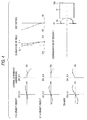
- Fig. 1 shows the optical path of the endoscopic objective lens of the invention.
- the planoconvex lens indicated by 10 is provided in front of the rod-shaped, gradient index lens 12 to reduce the angle of oblique incident light before said light is launched into the rod-shaped, gradient index lens 12.
- An aperture diaphragm 14 is provided ahead of the planoconvex lens 10 to eliminate the peripheral light apart from the optical axis.
- the gradient index lens 12 forms a real image at an end face 12a and the real image thus formed is transmitted through a fiber bundle 16 or other image transmitting optics to a point convenient for observation.
- Fig. 2 shows the optical path of a comparative case solely comprised of the gradient index lens 12.
- the objective lens of the invention uses the gradient index lens 12 having the same value of n o ⁇ g ⁇ r o as the comparative case, and yet it provides a far wider view angle.
- the gradient index lens used in the invention is so designed that the its on-axis refractive index n o is between 1.45 (inclusive) and 1.90 (inclusive) and this defines the range over which the lens can be practically manufactured by ion-exchange and other techniques.
- the value of n o ⁇ g ⁇ r o which corresponds to refractive power is adjusted to lie between 0.45 (inclusive) and 0.90 (inclusive). Below the lower limit 0.45, the obtained view angle is too narrow.
- the upper limit that can be readily attained by the current ion-exchange technology is about 0.7 and given future improvements in glass composition, it is extremely difficult to manufacture gradient index lenses with n o ⁇ g ⁇ r o values greater than 0.90.
- the view angle ⁇ that can be attained solely by the gradient index lens is 0.9 rad (about 52°).
- the effective radius r o of the gradient index lens is desirably in the range from 0.05 mm (inclusive) to 0.5 mm (inclusive).
- r o is desirably no more than 0.5 mm.
- a lens having r o less than 0.05 mm is extremely difficult to manufacture.
- the spherical aberration and curvature of field of the overall optics are corrected by gradient index coefficient h 4 , h 6 , h 8 , ....
- the value of h 4 is desirably in the range from -4 (inclusive) to +3 (inclusive).
- a gradient index lens with h 4 of less than -4 or greater than +3 is extremely difficult to manufacture.
- the refractive index n of the planoconvex lens is between 1.45 (inclusive) and 4.00 (inclusive). This condition is necessary to ensure that not only optical glass and plastics but also special grades of glass, crystals of high refractive index and semiconductors can be used as lens materials. Many semiconductors are opaque to visible light but in the infrared region very high refractive indices can be used as indicated below.
- the radius of curvature R of the convex spherical surface of the planoconvex lens is referenced to the effective radius r o of the gradient index lens and adjusted to lie between 0.8r o (inclusive) and 3.0 (inclusive). If R is less than 0.8r o , it is difficult to correct aberrations. If R is greater than 3.0r o , no wide visual field can be assured.
- planoconvex lens is made of optical glass or a plastic, its refractive index n is approximately between 1.45 (inclusive) and 2.2 (inclusive).
- the preferred range of R, or the radius of curvature of the convex spherical surface of the planoconvex lens is from 0.8r o (inclusive) to 1.95 r o (inclusive).
- the radius of the planoconvex lens is preferably adjusted to be nearly equal to that of the gradient index lens with which it is combined.
- the endoscopic objective lens of the invention preferably satisfies the following conditions:
- the present invention also provides an objective lens system installed in a distal end of an endoscope to form an in-focussed image of an object onto an image plane.
- the system comprises:
- the objective lens system further comprises: an aperture diaphragm located opposite from the gradient index lens with respect to the planoconvex lens, and the aperture diaphragm is attached to the planar surface of the planoconvex lens.
- the end surface of the gradient index lens is in contact with the convex surface of the planoconvex lens.
- planoconvex lens in the objective lens system satisfies the following conditions: 1.45 ⁇ n ⁇ 4.00 0.8r o ⁇ R ⁇ 3.0r o where
- planoconvex lens and the gradient index lens in the objective lens system further satisfy the followings: satisfies the following conditions:
- a planoconvex lens having a homogeneous refractive index and a gradient index lens having a gradient refractive index are made integral, with their optical axes being brought into alignment.
- An example of the structure of the assembly is shown in Fig. 3. The following is a recommended procedure for assembling the two lenses.
- an aperture diaphragm 14 having a central opening 14a in a plate member is fitted or attached to the planar side of the planoconvex lens 10. Then, as shown in Fig.
- the gradient index lens 12 and a fiber bundle 16 in mutual abutment are contained in a cover tube 18, and the planoconvex lens 10 with the aperture diaphragm 14 attached in the manner shown in Fig. 3A is mounted in the distal end portion of the cover tube 18 such that its convex surface contacts an end face of the gradient index lens 12.
- the preferred method is by applying a uv curable resin and allowing it to cure upon exposure to uv radiation.
- the objective lens of the invention is desirably used with light including visible light at wavelengths of about 0.3 to 2 ⁇ m. UV light at wavelengths shorter than 0.3 ⁇ m are substantially absorbed by the lens material. Considering the use of a CCD or an image pickup tube, the suitable wavelength of light is no longer than 2 ⁇ m.
- the endoscopic objective lens of the invention is solely made up of lenses having positive refractive index and hence involves difficulty in correcting chromatic aberrations.
- the absolute values of chromatic aberrations are tolerably small.
- the view angle is greater than 50°. It should be particularly noted that except in design No. 3, the view angle is even wider than 55°.
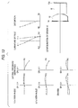
- Figs. 4 to 16 The configurations of the respective design No., as well as the lateral chromatic aberration, curvature of field and distortion that develop in them are shown in Figs. 4 to 16.
- the lateral chromatic aberration is indicated for three cases, on the optical axis, at 0.7 times the object height, and at 1.0 time the object height.
- the lateral chromatic aberration is indicated for the following three cases, on the optical axis, at 0.7 times the view angle, and at 1.0 time the view angle.
- DY and DX represent the aberrations in tangential and sagittal directions, respectively, with r o taken as unity (1).
- FY and FX represent the positions in which the rays of light pass through the aperture diaphragm, the terminal end of each defining the radius of the aperture.
- the curvature of field is expressed in both a sagittal direction S and a tangential direction T; length is expressed with r o taken as unity and the terminal end of each vertical axis defines the image height.
- the horizontal axis of the graph plotting the distortion is graduated by percentage and the terminal end of the vertical axis plots the image height.
- numeral 10 indicates the planoconvex lens having the homogeneous refractive index, 12 the gradient index lens, 12a its end face (coinciding with the image plane) and 14 the aperture diaphragm.
- Fig. 18 shows MTF values (100 line pairs per millimeter) for design No. 13 near the image plane.
- T represents a tangential image and S a sagittal image.
- MTF values of at least about 60% are assured at the aforementioned three points, on-axis, 0.7 times the object height and 1.0 time the object height. If the position of the image plane is modified to the best position on the optical axis (0.01 mm from the image plane), a maximum of about 80% is obtained for the on-axis MTF value.
Landscapes
- Physics & Mathematics (AREA)
- Astronomy & Astrophysics (AREA)
- General Physics & Mathematics (AREA)
- Optics & Photonics (AREA)
- Lenses (AREA)
- Endoscopes (AREA)
- Instruments For Viewing The Inside Of Hollow Bodies (AREA)
Applications Claiming Priority (2)
| Application Number | Priority Date | Filing Date | Title |
|---|---|---|---|
| JP32802298 | 1998-11-18 | ||
| JP10328022A JP2000147392A (ja) | 1998-11-18 | 1998-11-18 | 内視鏡用対物レンズ |
Publications (3)
| Publication Number | Publication Date |
|---|---|
| EP1003059A2 true EP1003059A2 (de) | 2000-05-24 |
| EP1003059A3 EP1003059A3 (de) | 2001-06-27 |
| EP1003059B1 EP1003059B1 (de) | 2003-10-08 |
Family
ID=18205653
Family Applications (1)
| Application Number | Title | Priority Date | Filing Date |
|---|---|---|---|
| EP99120805A Expired - Lifetime EP1003059B1 (de) | 1998-11-18 | 1999-10-21 | Endoskop-Objektiv |
Country Status (6)
| Country | Link |
|---|---|
| US (1) | US6252722B1 (de) |
| EP (1) | EP1003059B1 (de) |
| JP (1) | JP2000147392A (de) |
| CN (1) | CN1254099A (de) |
| DE (1) | DE69911889T2 (de) |
| TW (1) | TW434415B (de) |
Cited By (1)
| Publication number | Priority date | Publication date | Assignee | Title |
|---|---|---|---|---|
| EP1231486A1 (de) * | 2001-02-07 | 2002-08-14 | Nippon Sheet Glass Co., Ltd. | Stablinsen-Matrix für optisches Abbildungssystem |
Families Citing this family (17)
| Publication number | Priority date | Publication date | Assignee | Title |
|---|---|---|---|---|
| JP2001188167A (ja) * | 1999-12-28 | 2001-07-10 | Sekinosu Kk | プロジェクション用レンズ装置 |
| JP3781404B2 (ja) * | 2000-03-31 | 2006-05-31 | キヤノン株式会社 | 画像形成装置 |
| DE102005006052A1 (de) | 2004-12-21 | 2006-07-06 | Osram Opto Semiconductors Gmbh | Linse, Laseranordnung und Verfahren zur Herstellung einer Laseranordnung |
| JP4704069B2 (ja) * | 2005-02-28 | 2011-06-15 | 富士フイルム株式会社 | 内視鏡照明光学系 |
| JP2007041314A (ja) * | 2005-08-03 | 2007-02-15 | Pentax Corp | 対物レンズ及びその成形型、並びに対物レンズの製造方法 |
| DE102006046555B4 (de) * | 2006-09-28 | 2010-12-16 | Grintech Gmbh | Miniaturisiertes optisch abbildendes System mit hoher lateraler und axialer Auflösung |
| JP4339883B2 (ja) * | 2006-11-17 | 2009-10-07 | オリンパスメディカルシステムズ株式会社 | 撮像モジュール及び撮像モジュール用結像レンズ、並びに、撮像モジュールを用いた内視鏡 |
| EP2034286B1 (de) * | 2007-09-07 | 2012-10-31 | X-Rite Europe GmbH | Verfahren zur Druckprozesskontrolle unter Verwendung eines spektralen Messsystems mit spatialem Lichtmodulator |
| JP2009276502A (ja) * | 2008-05-14 | 2009-11-26 | Olympus Medical Systems Corp | 内視鏡用照明光学系 |
| WO2013024822A1 (ja) * | 2011-08-12 | 2013-02-21 | 株式会社フジクラ | 光ファイバ構造体、照明装置、内視鏡、および、光ファイバ構造体の製造方法 |
| KR101431105B1 (ko) * | 2013-09-02 | 2014-08-18 | 주식회사 소모홀딩스엔테크놀러지 | 휴대폰 적외선 센서용 렌즈 |
| US9915818B2 (en) | 2015-03-18 | 2018-03-13 | Himax Technologies Limited | End structure for endoscope |
| TWI551882B (zh) * | 2015-03-26 | 2016-10-01 | 奇景光電股份有限公司 | 影像透鏡系統 |
| JP6029159B1 (ja) * | 2016-05-13 | 2016-11-24 | 株式会社タムロン | 観察光学系、観察撮像装置、観察撮像システム、結像レンズ系及び観察光学系の調整方法 |
| JPWO2018163498A1 (ja) * | 2017-03-08 | 2020-05-14 | ソニー・オリンパスメディカルソリューションズ株式会社 | 医療用装置および医療用装置の製造方法 |
| DE102019125912A1 (de) * | 2019-09-26 | 2021-04-01 | Schott Ag | Lichtleiter für Diagnose-, Operations- und/oder Therapiegerät |
| WO2024122020A1 (ja) * | 2022-12-08 | 2024-06-13 | オリンパス株式会社 | 像伝送ユニット、光学機器および像伝送ユニットの製造方法 |
Family Cites Families (8)
| Publication number | Priority date | Publication date | Assignee | Title |
|---|---|---|---|---|
| JPS5229238A (en) * | 1975-08-30 | 1977-03-04 | Olympus Optical Co Ltd | Inside-view mirror objective optical system |
| US5093719A (en) * | 1989-10-23 | 1992-03-03 | Manx Optical Corporation | Endoscopic gradient index optical systems |
| JPH04114112A (ja) * | 1990-09-04 | 1992-04-15 | Matsushita Electric Ind Co Ltd | 高開口数レンズ |
| JP3585297B2 (ja) * | 1995-09-12 | 2004-11-04 | オリンパス株式会社 | 対物レンズ |
| US5995295A (en) * | 1995-12-13 | 1999-11-30 | Olympus Optical Co., Ltd. | Lens system |
| JPH1090598A (ja) * | 1996-09-11 | 1998-04-10 | Olympus Optical Co Ltd | 組合わせレンズ |
| JPH11149038A (ja) * | 1997-09-12 | 1999-06-02 | Nippon Sheet Glass Co Ltd | 屈折率分布レンズを用いた光学系 |
| JPH11258497A (ja) * | 1998-03-09 | 1999-09-24 | Micro Opt:Kk | 対物レンズ光学系 |
-
1998
- 1998-11-18 JP JP10328022A patent/JP2000147392A/ja active Pending
-
1999
- 1999-10-07 US US09/414,073 patent/US6252722B1/en not_active Expired - Fee Related
- 1999-10-19 TW TW088118039A patent/TW434415B/zh active
- 1999-10-21 EP EP99120805A patent/EP1003059B1/de not_active Expired - Lifetime
- 1999-10-21 DE DE69911889T patent/DE69911889T2/de not_active Expired - Fee Related
- 1999-11-03 CN CN99122351.9A patent/CN1254099A/zh active Pending
Cited By (2)
| Publication number | Priority date | Publication date | Assignee | Title |
|---|---|---|---|---|
| EP1231486A1 (de) * | 2001-02-07 | 2002-08-14 | Nippon Sheet Glass Co., Ltd. | Stablinsen-Matrix für optisches Abbildungssystem |
| US7012721B2 (en) | 2001-02-07 | 2006-03-14 | Nippon Sheet Glass Company Limited | Optical imaging system with rod lens array |
Also Published As
| Publication number | Publication date |
|---|---|
| EP1003059B1 (de) | 2003-10-08 |
| DE69911889T2 (de) | 2004-07-29 |
| US6252722B1 (en) | 2001-06-26 |
| CN1254099A (zh) | 2000-05-24 |
| DE69911889D1 (de) | 2003-11-13 |
| JP2000147392A (ja) | 2000-05-26 |
| EP1003059A3 (de) | 2001-06-27 |
| TW434415B (en) | 2001-05-16 |
Similar Documents
| Publication | Publication Date | Title |
|---|---|---|
| EP1003059B1 (de) | Endoskop-Objektiv | |
| US10816778B2 (en) | Image capture system and imaging optical system | |
| US6438290B1 (en) | Micro-aspheric collimator lens | |
| US4819224A (en) | Wavelength multiplexer-demultiplexer corrected of geometric and chromatic aberrations | |
| US5311611A (en) | Imaging ball lens optically immersed with a fiber optic faceplate | |
| CN102067005B (zh) | 双片组摄像光学系统和具有它的摄像装置 | |
| KR101671451B1 (ko) | 촬영 렌즈 광학계 | |
| JPS6053294B2 (ja) | 4群構成fθレンズ系 | |
| KR101070991B1 (ko) | 어안 렌즈 | |
| KR102290303B1 (ko) | 광각 이미징 렌즈 | |
| US7450323B2 (en) | Imaging lens and imaging device including the imaging lens | |
| US9417429B2 (en) | Image pick-up apparatus | |
| US7177085B2 (en) | Multiple imaging system and method for designing same | |
| US6097545A (en) | Concentric lens with aspheric correction | |
| WO2018066641A1 (ja) | 撮像レンズ系及び撮像装置 | |
| JP3063485B2 (ja) | 反射光学系 | |
| KR102290734B1 (ko) | 광학 이미징 렌즈 | |
| US4979808A (en) | Endoscope objective lens system | |
| EP0723672B1 (de) | Weitwinkelobjektivsystem | |
| CN112384839B (zh) | 物镜光学系统和内窥镜 | |
| JP2021156953A (ja) | 撮像レンズ系及び撮像装置 | |
| JP3685278B2 (ja) | 撮像レンズ | |
| JP2011099963A (ja) | 高被写界深度マイクロ単レンズ | |
| CN113671708A (zh) | 光学系统和头戴显示设备 | |
| JPS6130244B2 (de) |
Legal Events
| Date | Code | Title | Description |
|---|---|---|---|
| PUAI | Public reference made under article 153(3) epc to a published international application that has entered the european phase |
Free format text: ORIGINAL CODE: 0009012 |
|
| AK | Designated contracting states |
Kind code of ref document: A2 Designated state(s): DE FR GB |
|
| AX | Request for extension of the european patent |
Free format text: AL;LT;LV;MK;RO;SI |
|
| PUAL | Search report despatched |
Free format text: ORIGINAL CODE: 0009013 |
|
| AK | Designated contracting states |
Kind code of ref document: A3 Designated state(s): AT BE CH CY DE DK ES FI FR GB GR IE IT LI LU MC NL PT SE |
|
| AX | Request for extension of the european patent |
Free format text: AL;LT;LV;MK;RO;SI |
|
| 17P | Request for examination filed |
Effective date: 20011219 |
|
| AKX | Designation fees paid |
Free format text: DE FR GB |
|
| 17Q | First examination report despatched |
Effective date: 20020726 |
|
| GRAH | Despatch of communication of intention to grant a patent |
Free format text: ORIGINAL CODE: EPIDOS IGRA |
|
| GRAH | Despatch of communication of intention to grant a patent |
Free format text: ORIGINAL CODE: EPIDOS IGRA |
|
| GRAA | (expected) grant |
Free format text: ORIGINAL CODE: 0009210 |
|
| AK | Designated contracting states |
Kind code of ref document: B1 Designated state(s): DE FR GB |
|
| REG | Reference to a national code |
Ref country code: GB Ref legal event code: FG4D |
|
| REF | Corresponds to: |
Ref document number: 69911889 Country of ref document: DE Date of ref document: 20031113 Kind code of ref document: P |
|
| ET | Fr: translation filed | ||
| PLBE | No opposition filed within time limit |
Free format text: ORIGINAL CODE: 0009261 |
|
| STAA | Information on the status of an ep patent application or granted ep patent |
Free format text: STATUS: NO OPPOSITION FILED WITHIN TIME LIMIT |
|
| 26N | No opposition filed |
Effective date: 20040709 |
|
| PGFP | Annual fee paid to national office [announced via postgrant information from national office to epo] |
Ref country code: DE Payment date: 20081016 Year of fee payment: 10 |
|
| PGFP | Annual fee paid to national office [announced via postgrant information from national office to epo] |
Ref country code: FR Payment date: 20081014 Year of fee payment: 10 |
|
| PGFP | Annual fee paid to national office [announced via postgrant information from national office to epo] |
Ref country code: GB Payment date: 20081015 Year of fee payment: 10 |
|
| REG | Reference to a national code |
Ref country code: FR Ref legal event code: ST Effective date: 20100630 |
|
| PG25 | Lapsed in a contracting state [announced via postgrant information from national office to epo] |
Ref country code: FR Free format text: LAPSE BECAUSE OF NON-PAYMENT OF DUE FEES Effective date: 20091102 Ref country code: DE Free format text: LAPSE BECAUSE OF NON-PAYMENT OF DUE FEES Effective date: 20100501 |
|
| PG25 | Lapsed in a contracting state [announced via postgrant information from national office to epo] |
Ref country code: GB Free format text: LAPSE BECAUSE OF NON-PAYMENT OF DUE FEES Effective date: 20091021 |