EP1003068B1 - Mécanisme d'obturateur - Google Patents
Mécanisme d'obturateur Download PDFInfo
- Publication number
- EP1003068B1 EP1003068B1 EP99120756A EP99120756A EP1003068B1 EP 1003068 B1 EP1003068 B1 EP 1003068B1 EP 99120756 A EP99120756 A EP 99120756A EP 99120756 A EP99120756 A EP 99120756A EP 1003068 B1 EP1003068 B1 EP 1003068B1
- Authority
- EP
- European Patent Office
- Prior art keywords
- shutter
- rotary plate
- swing arm
- engaging portion
- rotary
- Prior art date
- Legal status (The legal status is an assumption and is not a legal conclusion. Google has not performed a legal analysis and makes no representation as to the accuracy of the status listed.)
- Expired - Lifetime
Links
Images


Classifications
-
- G—PHYSICS
- G03—PHOTOGRAPHY; CINEMATOGRAPHY; ANALOGOUS TECHNIQUES USING WAVES OTHER THAN OPTICAL WAVES; ELECTROGRAPHY; HOLOGRAPHY
- G03B—APPARATUS OR ARRANGEMENTS FOR TAKING PHOTOGRAPHS OR FOR PROJECTING OR VIEWING THEM; APPARATUS OR ARRANGEMENTS EMPLOYING ANALOGOUS TECHNIQUES USING WAVES OTHER THAN OPTICAL WAVES; ACCESSORIES THEREFOR
- G03B9/00—Exposure-making shutters; Diaphragms
- G03B9/08—Shutters
-
- G—PHYSICS
- G03—PHOTOGRAPHY; CINEMATOGRAPHY; ANALOGOUS TECHNIQUES USING WAVES OTHER THAN OPTICAL WAVES; ELECTROGRAPHY; HOLOGRAPHY
- G03B—APPARATUS OR ARRANGEMENTS FOR TAKING PHOTOGRAPHS OR FOR PROJECTING OR VIEWING THEM; APPARATUS OR ARRANGEMENTS EMPLOYING ANALOGOUS TECHNIQUES USING WAVES OTHER THAN OPTICAL WAVES; ACCESSORIES THEREFOR
- G03B11/00—Filters or other obturators specially adapted for photographic purposes
- G03B11/04—Hoods or caps for eliminating unwanted light from lenses, viewfinders or focusing aids
- G03B11/06—Lens caps for exposure making
-
- H—ELECTRICITY
- H04—ELECTRIC COMMUNICATION TECHNIQUE
- H04N—PICTORIAL COMMUNICATION, e.g. TELEVISION
- H04N23/00—Cameras or camera modules comprising electronic image sensors; Control thereof
- H04N23/50—Constructional details
- H04N23/55—Optical parts specially adapted for electronic image sensors; Mounting thereof
Definitions
- the present invention relates to a shutter mechanism of a camera casing installed on a vehicle, and more particularly relates to a shutter mechanism capable of releasing a shutter from the casing when the shutter freezes to the camera casing.
- An automotive camera is installed on a vehicle body for the outdoor use.
- Such outdoor cameras are usually subjected to severe weather conditions including rain and snow.
- the camera casing is usually equipped with a shutter.
- the shutter is closed when the camera is not used for photographing.
- the outside air temperature decreases in the winter season.
- the water or moisture component entering in a narrow space between the casing and shutter may freeze in such a low-temperature condition.
- the shutter freezes to the casing freeze, a very large force is required to release the shutter from the casing against the binding force of ice.
- the shutter is driven by a high-power motor.
- Figs. 6A and 6B cooperatively illustrate a shutter motion of a conventional camera casing.
- a shutter 103 is swingable about a hinge 104 provided at an edge of the shutter 103.
- Fig. 6B shows a closed condition of the shutter 103. In this closed condition, water or moisture component may freeze in a narrow space between the shutter 103 and the casing 102.
- a torque of an approximately Fx1 ⁇ 2 is required.
- Figs. 7A and 7B cooperatively illustrate a shutter motion of another conventional camera casing.
- a shutter 203 is similar to a quarter pipe and is swingable about a rotary shaft 204.
- Fig. 7B shows a closed condition of the shutter 203.
- water or moisture component freezes in a narrow space between the shutter 203 and the casing 202
- the shutter 203 needs to be released from the ice 210 by using a shearing force. It means that a very large torque is required to release the shutter 203 from the ice 210.
- the above-described conventional shutter mechanism requires a large torque to release the shutter from the camera casing when the shutter freezes to the camera casing. It may be possible to employ a special releasing mechanism. However, the structure of the shutter mechanism will be complicated and the cost is increased. A low-power motor may be used for producing a large torque. However, it requires an enlarged size speed-reducing gear mechanism. When the speed-reducing gear mechanism has a large gear ratio, the open/close motion of the shutter becomes slow. It takes a relatively long time to open or close the shutter.
- An object of the present invention is to provide a shutter mechanism which is capable of releasing the shutter from the camera casing by using a low-power motor when they freeze together and also capable of promptly accomplishing the open/close operation of the shutter.
- the present invention provides a shutter mechanism as defined in claim 1.
- the positional relationship between the eccentric shaft and the engaging portion of the rotary plate is determined in such a manner that the engaging member is separated from the engaging portion when the shutter is located at a predetermined closed position, the shutter moves linearly when the rotary plate starts rotating, the engaging member engages with the engaging portion after the rotary plate rotates a predetermined angle, thereby allowing the shutter to rotate.
- the engaging portion is provided in an opposed relationship with the eccentric shaft across the rotary shaft.
- Another aspect of the present invention provides a method for driving a shutter as defined in claim 7.
- a small torque can be converted into a large force which is available for releasing the shutter from the camera casing when they freeze together.
- the shutter can be airtightly closed by the large force.
- the engaging member is disengaged from the engaging portion when the shutter is in a predetermined closed condition or in a predetermined opened condition, so that the swing arm moves linearly along the track or trail of the eccentric shaft immediately after the rotary plate starts rotating or immediately before the rotary plate stops rotating.
- a large force is available for opening and closing the shutter and the shutter can rotate speedily during the open/close motion.
- a shutter mechanism of the preferred embodiment of the present invention comprises a rotary plate driven by a motor.
- An eccentric shaft and a recessed portion are provided on the rotary plate.
- a shutter, the eccentric shaft, and a pin are connected by a swing arm.
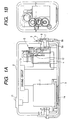
- Figs. 1A and 1B cooperatively show a shutter mechanism in accordance with a preferred embodiment of the present invention.
- Fig. 1A is a plan view.
- Fig. 1B is a side view.
- a camera 1 is a video camera installed on a vehicle body.
- a casing 2 accommodates the camera 1.
- a shutter 3 closes a photographing aperture 14 of the camera 1.
- a motor 4 drives the shutter 3.
- a gear mechanism 5 serves as a speed-reducing means for changing the rotation of the motor 4 into an appropriate value preferable for driving the shutter 3.
- a rotary plate 6 serves as a means for transmitting the rotation of the gear mechanism 5 to the shutter 3 via a swing arm 7.
- the swing arm 7 is integral with the shutter 3 for guiding a swing or rotational movement of the shutter 3.
- a pin 8 serves as a means for connecting the swing arm 7 to the rotary plate 6.
- a recessed portion 9 serves as a means for receiving the pin 8 to engage the pin 8 to the rotary plate 6.
- a driving circuit 13 drives the camera 1 and the motor 4.
- a connector 11 connects the driving circuit 13 to a control unit provided in the vehicle.
- a switch 12 is used to on-and-off control the motor 4 which is driven via the drive circuit 10.
- Figs. 2A to 2C are three-sided views cooperatively showing an appearance of the camera casing 2 incorporating the shutter mechanism in accordance with the preferred embodiment of the present invention.
- Fig. 2A is a plan view.
- Fig. 2B is a front view showing one side of the camera casing on which the shutter 3 is located.
- Fig. 2C is a side view showing another side of the camera casing 2 on which the rotary plate 6 is provided.
- Figs. 3A to 3F are views sequentially showing the operation of the shutter mechanism in accordance with the preferred embodiment of the present invention.
- Fig. 3A is a view showing an opened condition of the shutter 3 where the shutter 3 is swung upward (approximately 90°) to completely open the photographing aperture 14 of the camera 1.
- Fig. 3B is a view showing a rotation start condition where the shutter 3 is just integrated with the rotary plate 6 by the engagement between the pin 8 and the recessed portion 9.
- Figs. 3C to 3E are views sequentially showing the rotation of the shutter 3 under the condition where the engagement between the pin 8 and the recessed portion 9 is maintained.
- Fig. 3F is a view showing a closed condition of the shutter 3 where the pin 8 is disengaged from the recessed portion 9 and the shutter 3 stops to completely close the photographing aperture 14.
- Fig. 4 is a side view showing the operation of the shutter mechanism in accordance with the preferred embodiment of the present invention, corresponding to the overlap view of Figs. 3A to 3F.
- Fig. 5 is a view showing the movement of the swing arm 7 and the shutter 3, corresponding the overlap view of Figs. 3A, 3C, 3D and 3F.
- the casing 2 and the rotary plate 6 are omitted.
- the shutter mechanism in accordance with the preferred embodiment of the present invention has the above-described arrangement. The detailed operation of this shutter mechanism will be explained with reference to Figs. 1 to 5.
- the casing 2 has the photographing aperture 14 at a predetermined position corresponding to the lens of the camera 1.
- the shutter 3 is provided to cover the photographing aperture 14.
- the shutter 3 rotates about the output shaft of the gear mechanism 5 which is connected to the motor 4.
- the motor 4 rotates the rotary plate 6 via the gear mechanism 5.
- the rotary plate 6 has a rotary shaft 6a located at the center thereof.
- the rotary shaft 6a is connected to the output shaft of the gear mechanism 5.
- the other swing arm of the shutter 3 is rotatably supported by a shaft fixed to an opposite surface of the casing 2.
- An eccentric shaft 6b is located near the rotary shaft (i.e. central axis) 6a of the rotary plate 6. In other words, the eccentric shaft 6b is offset from the rotary shaft 6a.
- the swing arm 7 is rotatably supported by the eccentric shaft 6b.
- the swing arm 7 has one end integral with (i.e., stationarily connected to) the shutter 3.
- the pin 8 is provided on the opposite end of the swing arm 7.
- a spring is interposed between the pin 8 and the swing arm 7.
- the pin 8 is resiliently urged toward the rotary plate 6.
- the pin 8 is resiliently urged toward the rotary plate 6 by the resilient force obtained from the swing arm 7.
- the rotary plate 6 has the recessed portion 9 which is spaced from the rotary shaft 6a.
- the distance between the recessed portion 9 and the rotary shaft 6a is larger than the distance between the eccentric shaft 6b and the rotary shaft 6a.
- the recessed portion 9 serves as the engaging portion which is engageable with the pin 8.
- the motor 4 rotates to shift the shutter 3 linearly (i.e., raises the shutter 3 in the upper direction) from the opened position shown in Fig. 3A to the rotation start position shown in Fig. 3B.
- the shutter 3 is easily released from the casing 2 because the shutter 3 is rotated by a larger force.
- the rotary plate 6 further rotates, the pin 8 engages with the recessed portion 9.
- the shutter 3 is integrated with the swing arm 7 and they rotate together as shown in Figs. 3B to 3E.
- Fig. 5 shows the positional change of the shutter 3 during this rotation (refer to arc lines).
- the opening operation of shutter 3 is performed in the following manner.
- a line connecting the recessed portion 9 of the rotary plate 6 and the eccentric shaft 6b across the rotary shaft 6a is perpendicular to the longitudinal direction of the swing arm 7.
- the pin 8 is disengaged from the recessed portion 9 in this condition.
- the pin 8 is pressed to the rotary plate 6 by the resilient force of the arm 7.
- the eccentric shaft 6b shifts the swing arm 7 linearly (i.e., pushes the shutter 3 in the forward direction) as shown in Fig. 3E.
- the distance between the rotary shaft 6a and the eccentric shaft 6b is short.
- the shutter 3 is easily released from the casing 2 even when they freeze together.
- the rotary plate 6 When the rotary plate 6 further rotates, the pin 8 of the swing arm 7 engages with the recessed portion 9.
- the rotary plate 6 is integrated with the swing arm 7.
- the shutter 3 starts rotating, as shown in Figs. 3E to 3B. As the shutter 3 is already released from the frozen condition, the shutter 3 can easily rotate by a small torque. Thus, the shutter 3 rotates quickly and accomplishes the opening operation.
- Fig. 4 shows the movement of the shutter 3 in the vicinity of the opened position as well as in the vicinity of the closed position.
- Fig. 5 shows the positional change of the shutter 3 during the rotation.
- the swing arm 7 can rotate about the eccentric shaft 6b after the pin 8 departs from the opened position until it engages with the recessed portion 9.
- the swing arm 7 can rotate about the eccentric shaft 6b after the pin 8 departs from the closed position until it engages with the recessed portion 9.
- the shape of the rotary plate 6 is not limited to a circular disk, and therefore can be modified into an appropriate shape as long as it has a sufficient size for receiving the pin 8 which rolls on the surface of the rotary plate 6.
- the motor 4 has an appropriate torque and rotates at proper speeds, it may be possible to remove the gear mechanism 5.
- the motor 4 is directly and coaxially connected to the rotary plate 6.
- the swing arm 7 has a disklike shape.
- the rotary plate 6 can be thinned.
- the pin 8 and the recessed portion 9 can be replaced by other comparable engaging members, such as magnets, which are separable when a predetermined force is applied.
- the shutter mechanism is characterized in that the eccentric shaft 6b is provided at an offset position spaced from the rotary shaft 6a of the rotary plate 6 and the shutter 3 is connected to the eccentric shaft 6b via the swing arm 7.
- the pin 8 of the swing arm 7 is engaged with the recessed portion 9 of the rotary plate 6, the shutter 3 is integrated with the rotary plate 6.
- the shutter 3 is pushed by a strong force.
- the present invention provides a shutter mechanism comprising a rotary plate having an eccentric shaft separated from a rotary shaft and an engaging portion, a driving member for driving the rotary plate, a swing arm connecting a shutter to the eccentric shaft and rotatable about the eccentric shaft, and an engaging member provided on the swing arm.
- the swing arm is integrated with the rotary plate when the engaging portion of the rotary plate engages with the engaging member.
- the engaging member is disengaged from the engaging portion when a predetermined torque acts on the swing arm.
Landscapes
- Physics & Mathematics (AREA)
- General Physics & Mathematics (AREA)
- Engineering & Computer Science (AREA)
- Multimedia (AREA)
- Signal Processing (AREA)
- Studio Devices (AREA)
- Electrically Driven Valve-Operating Means (AREA)
- Accessories Of Cameras (AREA)
- Shutters For Cameras (AREA)
Claims (5)
- Mécanisme d'élément d'obturation destiné à un boítier d'appareil de prise de vues (2) qui loge un appareil de prise de vues (1), comprenant:caractérisé en ce que :un élément d'obturation (3),une plaque rotative (6) pouvant tourner autour d'un axe rotatif (6a),un élément d'entraínement (4) destiné à entraíner ladite plaque rotative (6) autour dudit axe rotatif (6a), etun bras oscillant (7) guidant une opération d'ouverture/fermeture de l'élément d'obturation (3),ladite plaque rotative (6) comporte un axe d'excentrique (6b) et une partie d'engagement (9) espacée dudit axe rotatif (6a),ledit bras oscillant (7) à une première extrémité relie ledit élément d'obturation (3) audit axe d'excentrique (6b) et peut tourner autour dudit axe d'excentrique (6b), etun élément d'engagement (8) est prévu sur l'autre extrémité dudit bras oscillant (7), de sorte que la rotation de la plaque rotative amène ledit élément d'engagement à s'engager avec ladite partie d'engagementde sorte que ledit bras oscillant (7) tourne en étant relié de façon fixe à ladite plaque rotative (6) tant que ladite partie d'engagement (9) de ladite plaque rotative (6) s'engage avec ledit élément d'engagement (8), etledit élément d'engagement (8) se dégage de ladite partie d'engagement (9) lorsqu'un couple prédéterminé appliqué à l'élément d'obturation (3) par le boítier (2) agit sur ledit bras oscillant (7).
- Mécanisme d'élément d'obturation selon la revendication 1, dans lequel la relation de position entre ledit axe d'excentrique (6b) et ladite partie d'engagement (9) de ladite plaque rotative (6) est déterminée de telle manière que ledit élément d'engagement (8) est séparé de ladite partie d'engagement (9) lorsque ledit élément d'obturation (3) se trouve dans un état fermé prédéterminé, ledit élément d'obturation (3) se déplace. linéairement lorsque ladite plaque rotative (6) commence à tourner, ledit élément d'engagement (8) s'engage avec ladite partie d'engagement (9) après que ladite plaque rotative (6) tourne d'un angle prédéterminé, permettant ainsi que ledit élément d'obturation (3) tourne autour dudit axe rotatif (6a) en même temps que ladite plaque rotative (6).
- Mécanisme d'élément d'obturation selon la revendication 1, dans lequel ladite partie d'engagement (9) est prévue dans une relation opposée avec ledit axe d'excentrique (6b) en travers dudit axe rotatif (6a).
- Procédé d'entraínement d'un élément d'obturation (3) d'un boítier d'appareil de prise de vues (2) qui loge un appareil de prise de vues (1), ledit élément d'obturation étant relié à une extrémité d'un bras oscillant (7) en faisant tourner une plaque rotative (6) autour d'un axe rotatif (6a), où le bras oscillant (7) est relié à un axe d'excentrique (6b) espacé dudit axe rotatif (6a), ledit procédé comprenant les étapes consistant à :actionner un élément d'entraínement (4) pour faire tourner ladite plaque rotative (6) autour dudit axe rotatif (6a),engager une partie d'engagement (9) de ladite plaque rotative avec un élément d'engagement (8) à l'autre extrémité du bras oscillant conformément à une rotation de ladite plaque rotative (6) de sorte que ledit bras oscillant (7) tourne en étant relié de façon fixe à ladite plaque rotative (6) et de façon à faire tourner ledit élément d'obturation (3) en même temps que ledit bras oscillant (7) tant que ladite partie d'engagement (9) s'engage avec ledit élément d'engagement (8), etdégager ledit élément d'engagement (8) de ladite partie d'engagement (9) lorsqu'un couple prédéterminé appliqué à l'élément d'obturation (3) par le boítier (2) agit sur ledit bras oscillant (7) de façon à amener ledit élément d'obturation (3) et ledit bras oscillant (7) à se déplacer linéairement par l'intermédiaire dudit axe d'excentrique (6b).
- Dispositif d'entraínement d'élément d'obturation selon là revendication 4, dans lequel ledit élément d'engagement (8) est dégagé de ladite partie d'engagement (9) lorsque ledit élément d'obturation (3) se trouve dans un état fermé prédéterminé ou dans un état ouvert prédéterminé, de sorte que ledit bras oscillant (7) se déplace linéairement le long de la voie ou de la piste dudit axe d'excentrique (6b) immédiatement après que ladite plaque rotative (6) commence à tourner ou immédiatement avant que ladite plaque rotative (6) arrête de tourner.
Applications Claiming Priority (2)
| Application Number | Priority Date | Filing Date | Title |
|---|---|---|---|
| JP33144798A JP4167334B2 (ja) | 1998-11-20 | 1998-11-20 | 車載カメラケース用シャッター機構 |
| JP33144798 | 1998-11-20 |
Publications (2)
| Publication Number | Publication Date |
|---|---|
| EP1003068A1 EP1003068A1 (fr) | 2000-05-24 |
| EP1003068B1 true EP1003068B1 (fr) | 2004-06-16 |
Family
ID=18243763
Family Applications (1)
| Application Number | Title | Priority Date | Filing Date |
|---|---|---|---|
| EP99120756A Expired - Lifetime EP1003068B1 (fr) | 1998-11-20 | 1999-10-20 | Mécanisme d'obturateur |
Country Status (5)
| Country | Link |
|---|---|
| US (1) | US6382847B1 (fr) |
| EP (1) | EP1003068B1 (fr) |
| JP (1) | JP4167334B2 (fr) |
| CN (1) | CN1122872C (fr) |
| DE (1) | DE69918032T2 (fr) |
Cited By (1)
| Publication number | Priority date | Publication date | Assignee | Title |
|---|---|---|---|---|
| WO2011154290A2 (fr) | 2010-06-11 | 2011-12-15 | Huf Hülsbeck & Fürst Gmbh & Co. Kg | Dispositif équipé d'une unité caméra |
Families Citing this family (5)
| Publication number | Priority date | Publication date | Assignee | Title |
|---|---|---|---|---|
| DE102007052402B4 (de) * | 2007-10-31 | 2020-12-17 | Huf Hülsbeck & Fürst Gmbh & Co. Kg | Vorrichtung mit einer Kameraeinheit und Verfahren zum Betrieb einer solchen Vorrichtung |
| DE102007052401B4 (de) * | 2007-10-31 | 2019-01-24 | Huf Hülsbeck & Fürst Gmbh & Co. Kg | Vorrichtung mit einer Kameraeinheit |
| DE102009008283B4 (de) | 2009-02-10 | 2021-10-07 | Huf Hülsbeck & Fürst Gmbh & Co. Kg | Vorrichtung mit einer Deckeleinheit zum Schutz einer Kameraeinheit und Betätigungsverfahren für eine derartige Vorrichtung |
| JP5005073B2 (ja) * | 2010-07-20 | 2012-08-22 | 本田技研工業株式会社 | 車両のシャッタ装置 |
| US9762777B2 (en) | 2013-04-24 | 2017-09-12 | Huf Hülsbeck & Fürst Gmbh & Co. Kg | Device with a camera unit |
Family Cites Families (6)
| Publication number | Priority date | Publication date | Assignee | Title |
|---|---|---|---|---|
| US1020383A (en) * | 1912-03-12 | Cameron Picture Machine Company | Moving-picture machine. | |
| JPS56106229A (en) * | 1980-01-25 | 1981-08-24 | Canon Inc | Camera with electromagnetic driving source |
| JPS587621A (ja) * | 1981-07-07 | 1983-01-17 | Canon Inc | シヤツタ−開閉装置 |
| US4547051A (en) * | 1983-12-16 | 1985-10-15 | Nisus Video Incorporated | Shutter for a video tape camera |
| US4699483A (en) * | 1983-12-16 | 1987-10-13 | Swinehart Steven L | Device for adjusting a video tape camera shutter mechanism |
| JPH0624823Y2 (ja) * | 1988-05-11 | 1994-06-29 | 株式会社精工舎 | カメラ用フォーカルプレーンシャッタ |
-
1998
- 1998-11-20 JP JP33144798A patent/JP4167334B2/ja not_active Expired - Lifetime
-
1999
- 1999-10-20 DE DE69918032T patent/DE69918032T2/de not_active Expired - Fee Related
- 1999-10-20 EP EP99120756A patent/EP1003068B1/fr not_active Expired - Lifetime
- 1999-10-21 CN CN99123141A patent/CN1122872C/zh not_active Expired - Fee Related
- 1999-10-27 US US09/427,704 patent/US6382847B1/en not_active Expired - Fee Related
Cited By (3)
| Publication number | Priority date | Publication date | Assignee | Title |
|---|---|---|---|---|
| WO2011154290A2 (fr) | 2010-06-11 | 2011-12-15 | Huf Hülsbeck & Fürst Gmbh & Co. Kg | Dispositif équipé d'une unité caméra |
| EP2590014A1 (fr) | 2010-06-11 | 2013-05-08 | Huf Hülsbeck & Fürst GmbH & Co. KG | Dispositif en tant que groupe de montage pour une caméra à une véhicule automobile |
| EP2590015A1 (fr) | 2010-06-11 | 2013-05-08 | Huf Hülsbeck & Fürst GmbH & Co. KG | Dispositif doté d'un élément de montage et couvercle pour véhicule automobile |
Also Published As
| Publication number | Publication date |
|---|---|
| JP4167334B2 (ja) | 2008-10-15 |
| US6382847B1 (en) | 2002-05-07 |
| JP2000165712A (ja) | 2000-06-16 |
| CN1254855A (zh) | 2000-05-31 |
| DE69918032D1 (de) | 2004-07-22 |
| DE69918032T2 (de) | 2005-06-30 |
| EP1003068A1 (fr) | 2000-05-24 |
| CN1122872C (zh) | 2003-10-01 |
Similar Documents
| Publication | Publication Date | Title |
|---|---|---|
| JP2855557B2 (ja) | 自動車用ドアロック装置 | |
| US6685239B2 (en) | Vehicle door opening closing device | |
| US4152866A (en) | Electrically driven travelling toy | |
| EP1003068B1 (fr) | Mécanisme d'obturateur | |
| JP3708622B2 (ja) | 手動・自動切換装置 | |
| KR20190084447A (ko) | 냉장고용 제빙기 구동장치 | |
| JP4276737B2 (ja) | 電気機器 | |
| KR950001696A (ko) | 미니디스크 플레이어 구동장치 | |
| US4240734A (en) | Motor-drive camera using a cartridge film | |
| KR910001633B1 (ko) | 동력구동식 램프덮개를 가지는 차량조명장치 | |
| KR940006138B1 (ko) | 자기 테이프 장치 | |
| JPS596500Y2 (ja) | 電気機器におけるドアの開閉装置 | |
| US5504634A (en) | Video tape cassette adapter | |
| JPH10319475A (ja) | バリア付カメラ | |
| JP3082584B2 (ja) | ばね蓄勢操作装置 | |
| JP4689036B2 (ja) | 絞り機構付シャッタ装置 | |
| JPS6232275Y2 (fr) | ||
| KR940001108Y1 (ko) | 로직데크의 키 오프(Key Off)장치 | |
| CA2132585C (fr) | Adaptateur pour cassette de bande magnetique video | |
| JPS6134497Y2 (fr) | ||
| US6122146A (en) | Autostop mechanism for tape driving apparatus | |
| US4448507A (en) | Camera | |
| JPS6241414Y2 (fr) | ||
| JPS6364822B2 (fr) | ||
| JPH0244355Y2 (fr) |
Legal Events
| Date | Code | Title | Description |
|---|---|---|---|
| PUAI | Public reference made under article 153(3) epc to a published international application that has entered the european phase |
Free format text: ORIGINAL CODE: 0009012 |
|
| AK | Designated contracting states |
Kind code of ref document: A1 Designated state(s): DE FR GB |
|
| AX | Request for extension of the european patent |
Free format text: AL;LT;LV;MK;RO;SI |
|
| 17P | Request for examination filed |
Effective date: 20000913 |
|
| AKX | Designation fees paid |
Free format text: DE FR GB |
|
| GRAP | Despatch of communication of intention to grant a patent |
Free format text: ORIGINAL CODE: EPIDOSNIGR1 |
|
| GRAS | Grant fee paid |
Free format text: ORIGINAL CODE: EPIDOSNIGR3 |
|
| GRAA | (expected) grant |
Free format text: ORIGINAL CODE: 0009210 |
|
| RAP1 | Party data changed (applicant data changed or rights of an application transferred) |
Owner name: MATSUSHITA ELECTRIC INDUSTRIAL CO., LTD. |
|
| AK | Designated contracting states |
Kind code of ref document: B1 Designated state(s): DE FR GB |
|
| REG | Reference to a national code |
Ref country code: GB Ref legal event code: FG4D |
|
| REF | Corresponds to: |
Ref document number: 69918032 Country of ref document: DE Date of ref document: 20040722 Kind code of ref document: P |
|
| ET | Fr: translation filed | ||
| PLBE | No opposition filed within time limit |
Free format text: ORIGINAL CODE: 0009261 |
|
| STAA | Information on the status of an ep patent application or granted ep patent |
Free format text: STATUS: NO OPPOSITION FILED WITHIN TIME LIMIT |
|
| 26N | No opposition filed |
Effective date: 20050317 |
|
| PGFP | Annual fee paid to national office [announced via postgrant information from national office to epo] |
Ref country code: DE Payment date: 20071018 Year of fee payment: 9 |
|
| PGFP | Annual fee paid to national office [announced via postgrant information from national office to epo] |
Ref country code: GB Payment date: 20071017 Year of fee payment: 9 Ref country code: FR Payment date: 20071009 Year of fee payment: 9 |
|
| GBPC | Gb: european patent ceased through non-payment of renewal fee |
Effective date: 20081020 |
|
| REG | Reference to a national code |
Ref country code: FR Ref legal event code: ST Effective date: 20090630 |
|
| PG25 | Lapsed in a contracting state [announced via postgrant information from national office to epo] |
Ref country code: DE Free format text: LAPSE BECAUSE OF NON-PAYMENT OF DUE FEES Effective date: 20090501 |
|
| PG25 | Lapsed in a contracting state [announced via postgrant information from national office to epo] |
Ref country code: FR Free format text: LAPSE BECAUSE OF NON-PAYMENT OF DUE FEES Effective date: 20081031 |
|
| PG25 | Lapsed in a contracting state [announced via postgrant information from national office to epo] |
Ref country code: GB Free format text: LAPSE BECAUSE OF NON-PAYMENT OF DUE FEES Effective date: 20081020 |