EP1003172A2 - Cassette à bande - Google Patents
Cassette à bande Download PDFInfo
- Publication number
- EP1003172A2 EP1003172A2 EP99122768A EP99122768A EP1003172A2 EP 1003172 A2 EP1003172 A2 EP 1003172A2 EP 99122768 A EP99122768 A EP 99122768A EP 99122768 A EP99122768 A EP 99122768A EP 1003172 A2 EP1003172 A2 EP 1003172A2
- Authority
- EP
- European Patent Office
- Prior art keywords
- brake
- tape
- reel
- reel brake
- case
- Prior art date
- Legal status (The legal status is an assumption and is not a legal conclusion. Google has not performed a legal analysis and makes no representation as to the accuracy of the status listed.)
- Withdrawn
Links
- 238000003780 insertion Methods 0.000 claims abstract description 11
- 230000037431 insertion Effects 0.000 claims abstract description 11
- 230000001105 regulatory effect Effects 0.000 claims description 148
- 238000010276 construction Methods 0.000 description 17
- 230000007246 mechanism Effects 0.000 description 16
- 238000004519 manufacturing process Methods 0.000 description 8
- 239000011347 resin Substances 0.000 description 5
- 229920005989 resin Polymers 0.000 description 5
- 230000000694 effects Effects 0.000 description 4
- 238000005192 partition Methods 0.000 description 4
- 238000010521 absorption reaction Methods 0.000 description 2
- 238000013459 approach Methods 0.000 description 2
- 230000008859 change Effects 0.000 description 2
- 239000000463 material Substances 0.000 description 2
- 230000003287 optical effect Effects 0.000 description 2
- 238000003825 pressing Methods 0.000 description 2
- 238000003466 welding Methods 0.000 description 2
- 239000004743 Polypropylene Substances 0.000 description 1
- 230000009471 action Effects 0.000 description 1
- 238000005452 bending Methods 0.000 description 1
- 238000005520 cutting process Methods 0.000 description 1
- 230000004048 modification Effects 0.000 description 1
- 238000012986 modification Methods 0.000 description 1
- 238000000465 moulding Methods 0.000 description 1
- 230000010355 oscillation Effects 0.000 description 1
- 230000002093 peripheral effect Effects 0.000 description 1
- -1 polypropylene Polymers 0.000 description 1
- 229920001155 polypropylene Polymers 0.000 description 1
- 238000012545 processing Methods 0.000 description 1
Images
















Classifications
-
- G—PHYSICS
- G11—INFORMATION STORAGE
- G11B—INFORMATION STORAGE BASED ON RELATIVE MOVEMENT BETWEEN RECORD CARRIER AND TRANSDUCER
- G11B23/00—Record carriers not specific to the method of recording or reproducing; Accessories, e.g. containers, specially adapted for co-operation with the recording or reproducing apparatus ; Intermediate mediums; Apparatus or processes specially adapted for their manufacture
- G11B23/02—Containers; Storing means both adapted to cooperate with the recording or reproducing means
- G11B23/04—Magazines; Cassettes for webs or filaments
- G11B23/08—Magazines; Cassettes for webs or filaments for housing webs or filaments having two distinct ends
- G11B23/087—Magazines; Cassettes for webs or filaments for housing webs or filaments having two distinct ends using two different reels or cores
- G11B23/08707—Details
- G11B23/08721—Brakes for tapes or tape reels
Definitions
- the present invention relates to a tape cassette for use in a magnetic recording and reproducing device such as a video tape recorder (VTR) and more particularly to a tape cassette for use as a video tape cassette such as an 8mm video tape cassette and a digital video cassette (DVC) which has a tape-like medium received in a case thereof via tape reels and incorporates therein a reel brake mechanism for regulating the rotation of the tape reels when the tape cassette is not in use.
- VTR video tape recorder
- DVC digital video cassette
- a brake mechanism for stopping the rotation of the tape reels when the tape cassette is not in use which is constructed such that a brake member is biassed against teeth provided on outer circumferences of flanges of the tape reels by means of a resilient member such as a torsional coil spring and a leaf spring, and when this tape cassette so constructed is mounted in the recording and reproducing device, a brake releasing member of the recording and reproducing device is brought into abutment with the brake member and moves the brake member against the resilient force of the spring so as to disengage the brake member from the tape reels to thereby allow the tape reels to rotate (Japanese Unexamined Patent Publication Nos. 6-318383 and 10-112158, and Japanese Unexamined Utility Model Publication Nos. 3-106587 and 58-173073).
- Figs. 31A and 31B are plan views showing one example of a conventional reel brake for a tape cassette, Fig. 31A showing a state in which the reel brake is in normal use, and Fig. 31B showing a state in which pawls are deployed.
- Arms 826 are provided on left and right sides of a main body 821 of the reel brake 820 in such a manner as to outwardly protrude therefrom.
- This arm 826 and the pawl 822 are connected to each other at a thin hinge portion 824.
- the pawl 822 comprises a distal end portion 822a, a guided portion 822b and a root portion 822c which are integrally formed.
- the pawl 822 is formed so as to rotate about the hinge portion 824 as a fulcrum, and they are so constructed as to allow the pawl 822 to rotate appropriately when the distal end portion 822a of the pawl 822 is brought into engagement with teeth formed in a tape reel to thereby provide a smooth engagement between the pawl 822 and the teeth.
- the reel brake 820 is disposed in the tape cassette in a state as shown in Fig. 31A, in which the guided portion 822b engages a guide groove formed on a case main body side.
- the pawl 822 is unnecessarily rotated (excessive rotation), and moreover this repeatedly happens, since the thickness of the hinge portion 824 is extremely thin (e.g., on the order of 0.13mm), there is caused a cut (crack) in the hinge portion 824 and there may be even a case where the hinge portion 824 is cut thereat.
- the hinge portion 824 is cut while in use, thereby causing a problem that the reel brake cannot fulfill the function to lock the tape reels.
- the strength of the hinge portion 824 is improved if a resin material (for instance, polypropylene) is used which has a hinge effect strong enough to deal with repeated bending, since materials have to be selected while taking into consideration the moldability and slidability of the reel brake 820, there has been a certain limit to increasing the strength of the hinge portion 824.
- a resin material for instance, polypropylene
- Figs. 32A and 32B shows an example of another conventional reel brake, in which Fig. 32A is a plan view showing a state in which a reel brake 908 mounted in a lower case 902 engages teeth 903d formed in a tape reel 903 and Fig. 32B is a sectional view corresponding to a plane A-A of Fig. 32A and showing a state in which an upper case 901 is mounted on the lower case 902.
- the teeth 903d are formed in an outer circumference of the tape reel 903.
- the reel brake 908 is disposed slidably in vertical directions.
- Pawls 908c are provided on left and right sides of a main body 908a of the reel brake 908 which pawls are adapted to freely rotate via thinned hinge portions 908b, respectively.
- the reel brake 908 is biassed toward the tape reel 903 side by virtue of a spring force of a spring (not shown) when the tape cassette is not in use, and the tape reel 903 is locked when the pawl 908c of the reel brake 908 enters between the teeth 903d formed in the tape reel 903.
- the reel brake 908 is slid in a direction in which it moves away from the tape reel 903 against the biassing force of the spring, whereby the engagement between the reel brake 908 and the taple reel 903 is released.
- a position regulating portion 902b for regulating the position of the reel brake 908 is provided in the lower case 902 in such a manner as to erect therefrom.
- a front of the main body 908a of the reel brake 908 and a position regulating wall 902b are constructed so as to be brought into abutment with each other at a position where a distal end of the pawl 908c of the reel brake 908 engages the teeth 903d of the reel brake 903, whereby the reel brake 908 is prevented from sliding further toward the tape reel 903 side from this regulated position.
- the back of the main body 908a is a surface which is adapted to be brought into abutment with a spring for biassing the reel brake 908 and therefore the configuration thereof becomes complicated, and it is not preferable to provide the gate portion 908f in this back.
- the gate portion 908f is provided at a position offset either to the left-hand side or the right-hand side of the main body 908a, the formability of the thinned hinge portion 908 is deteriorated.
- brake release devices equipped on such devices or device side brake release devices have also been diversified.
- a cassette tape having a reel brake member that is maneuvered, for instance, with a pin the size and depth of openings formed in a lower case or on a lower surface side of a reel brake member are standardized, but in brake release members provided on a device side, there are pins of various configurations such as square pole-like or cylindrical pin, and the thickness thereof also ranges from thin to thick.
- the configuration of tips of pins ranges, and there are found slant and spherical tips, thus the thickness and configuration vary from manufacturer to manufacturer.
- an object of the present invention is to prevent the generation of a cut in a thin hinge portion via which a pawl of a reel brake for a tape cassette becomes rotatable due to excessive rotations of the pawl, for instance, while being transported.
- an object of the present invention is to prevent an interference between the gate portion of the reel brake and the position regulating portion of the case main body while maintaining the formability of the reel brake.
- the present invention was made to easily eliminate the aforesaid problems inherent in the prior art, and an object thereof is to provide at reasonable costs a tape cassette that can press for actuation a central portion of a reel brake member even if there are various types of reel brake members resulting from a variety of types of devices used together for a smooth brake releasing operation, which can maintain the normal brake function so as to eliminate a problem in handling for a secure brake operation and which incorporates therein a functionally satisfactory brake mechanism.
- the present invention was made to easily eliminate the aforesaid problems inherent in the prior art, and an object thereof is to provide a tape cassette wherein a reel brake mechanism for stopping the rotation of a pair of tape reels rotatably received inside a case of the tape cassette is constructed such that even if a strong impact such as a drop impact is exerted thereon, a brake engagement is not released to thereby prevent the production of a looseness of the tape so that the tape cassette can perfectly be used, wherein the reel brake mechanism is constructed such that a reel brake member is prevented from being moved even if the tape reels are moved inside the tape cassette to thereby eliminate unnecessary movements of the reel brake member so that the reel brake member can follow every movement of the tape reels, thereby making it possible to maintain a highly reliable reel brake performance, and wherein the number of components used is reduced to as few as possible so as to improve the assembling capability and increase the productivity, thereby making it possible to provide an inexpensive tape cassette incorporating therein a reel brake mechanism that can perform a positive brake operation and which
- a tape cassette comprises a reel brake for a tape cassette, a pair of tape reels around which a tape is wound being rotatably received in a case main body so as to prevent idle rotations of the tape reels through engagement with the tape reels when the tape cassette is not in use, wherein the reel brake comprises pawls provided on a main body thereof and each having a thinned hinge portion, the pawl being formed so as to rotate through the hinge portion and comprising a regulating portion for preventing excessive rotations of the pawl.
- the regulating portion comprises a regulating rib provided so as to extend from the vicinity of the hinge portion, and wherein an end of the regulating rib is adapted to abut with an end of an arm located on an opposite side and connected to the rib via the hinge portion when the pawl rotates excessively.
- the regulating portion comprises a regulating rib provided between a pair of the hinge portions of the main body.
- the pawl can rotate via the hinge portion, but when the pawl is rotated excessively, the pawl and the main body of the reel brake are brought into abutment with the regulating portion. Consequently, a further rotation of the pawl can be prevented, whereby even when reel brakes get entangled in each other to thereby rotate the pawls excessively, since a rotation of the pawl exceeding a certain angle is regulated by the regulating portion, the generation of a cut in the hinge portion can be prevented.
- a tape cassette comprises tape reels around which a tape-like medium being wound rotatably received in a case main body, a reel brake for preventing idle rotations of the tape reels through engagement with the tape reels when the tape cassette is not in use disposed slidably between a lock position for locking the tape reels and a lock releasing position for releasing the lock of the tape reels, and a position regulating portion provided in the case main body for regulating the position of the reel brake at a position where the reel brake locks the tape reels, wherein a gate portion for the reel brake is provided at a front of a main body of the reel brake, and wherein a run off portion is formed such that the gate portion formed at the front of the main body of the reel brake does not abut with the position regulating portion when the front of the main body of the reel brake is brought into abutment with the position regulating portion.
- a run off portion is
- the gate portion at the front of the main body of the reel brake does not abut with the position regulating portion. Therefore, even if there remains a projection (the remains of the gate) at the gate portion, the reel brake is allowed to slide to a position where the reel brake can be brought into secure abutment with the tape reels.
- the run off portion formed in the position regulating portion side functions to avoid a risk of an abutment between the gate portion of the reel brake and the position regulating portion. Therefore, there is no need to form a thickness saving portion or the like on the reel brake side.
- a tape cassette comprises a pair of tape reels around which a tape is wound rotatably received in a case, the tape being disposed so as to extend from one of the tape reels through a front of the case to the other tape reel to be wound up therearound, and a reel brake member having brake pawls for suppressing the rotation of the tape reels and provided so as to freely slide for engagement with and disengagement from teeth of said tape reels for braking operation and brake releasing operation, respectively, the reel brake member being biassed by a spring toward a tape reels side, wherein a main body of the reel brake member comprises an opening hole portion for insertion of a brake release member provided on a device side, and wherein a guide recessed portion is formed at a center of an abutment side wall portion of the brake release member within the opening hole portion for guiding the brake release member.
- the guide recessed portion is formed in a vertical direction in the abutment the wall portion of the brake release member at a central portion of the opening hole portion, and an internal surface of the guide recessed portion is formed into a curved surface.
- the abutment side wall portion of the brake release member is formed into an inclined surface on a lower the thereof, while the abutment side wall portion is formed into a vertical surface on an upper side thereof, and both sides of the guide recessed portion into which the brake release member is fittingly inserted are formed into flat surface portions
- a reel brake member biased by a resilient force so as to engage tape reels is restricted with respect to a movable range thereof by a regulating mechanism for preventing the movement of the reel brake member to such an extent that brake pawls of the reel brake member are released from an engagement with tape reels.
- the reel brake member comprises an opening hole portion for insertion of a brake release member provided on a device side, and a guide recessed portion is formed at a center of an abutment side wall portion of the brake release member within the opening hole portion for guiding the brake release member.
- a tape cassette comprises a pair of tape reels around which a tape is wound rotatably received in a case, the tape being disposed so as to extend from one of the tape reels through a front of the case to the other tape reel to be wound up therearound, and a reel brake member having brake pawls for suppressing the rotation of the tape reels and provided so as to freely slide for engagement with and disengagement from teeth of the tape reels for braking operation and brake releasing operation, respectively, the reel brake member being biassed by a spring toward a tape reels side, wherein a main body of the reel brake member comprises arms provided on sides thereof via hinge portions, each of the arms having a brake pawl provided on a distal end thereof, an opening hole portion formed therein for insertion of a brake release operating member provided on a device side, upper and lower surface portions adapted to abut with and slide over internal surfaces of upper and lower cases, recessed portions provided on sides of a front side of said upper surface portion at positions corresponding
- a regulating wall portion for regulating the sliding of the arm of the reel brake member is a guide rib
- the guide rib comprises a linear guide rib oriented toward a back side of the case and a curved guide rib provided on a front side of said case so as to extend outwardly.
- the linear guide rib and the curved guide rib are provided on internal surfaces of the upper and lower cases in such a manner as to protrude therefrom.
- the curved guide rib is provided so as to extend at a height which is taller than the linear guide rib.
- a projection is provided on the arm of the reel brake member in such a manner as to protrude therefrom for abutment with said guide rib, and guide wall portions which the arms of the reel brake member slide along and abut with are provided continuously with outer circumferential ribs provided along the tape reels receiving area.
- a regulating mechanism for regulating the movement of the reel brake member in a brake releasing direction functions as the regulating wall portion and prvents the arms of the reel brake member from deflecting inwardly of the brake when the tape cassette is not in use or while the brake releasing operation is being carried out, whereby the brake pawls are constructed not to disengage from the reel areas.
- the reel brake member closes inwardly the arms of the reel brake member in the vicinity of the brake releasing position so that the brake pawls disengage from the reel areas.
- a reel brake member biased by a resilient force so as to engage tape reels is restricted with respect to a movable range thereof by a regulating mechanism for preventing the movement of the reel brake member to such an extent that brake pawls of the reel brake member are released from an engagement with tape reels.
- the reel brake member comprises arms provided on both sides of a main body thereof via hinge portions, respectively, the respective arms having the brake pawls at distal ends thereof, a projection provided between the arm and the brake pawl, upper and lower surface portions adapted to slide over internal surfaces of upper and lower cases of the tape cassette, recessed portions formed on the upper surface portion on both sides of the front side at positions corresponding to outer circumferential edges of the tape reels, and a butt recessed portion formed on a front side of the lower surface portion in such a manner as to correspond to holding ribs provided on a front side of a reel brake sliding area of the lower case along a tape reel receiving area.
- a regulating wall portion for regulating the sliding of the arm of the reel brake member is a guide rib
- the guide rib comprises a linear guide rib oriented toward a back side of the case and a curved guide rib provided on a front side of the case so as to extend outwardly.
- the brake release means of the recording and reproducing device abuts with the brake release operating portion of the reel brake member to thereby slidingly move the reel brake member in the sliding operation so that the brake pawls are disengaged from the teeth of the tape reels for safely running of the tape.
- Fig. 1 is an exploded perspective view showing a tape cassette (DVC) to which a first mode of operation of the present invention is to applied.
- a case main body comprises an upper case 101 and a lower case 102.
- a pair of tape reels 103 around which a tape-like medium (magnetic tape) 104 for recording information thereon is wound are rotatably received in the case main body.
- the tape reel 103 comprises a lower flange 103a formed integrally with a hub portion 103b and a transparent upper flange 103c secured to an upper surface of the hub portion 103 by means of welding or the like.
- the tape-like medium 104 is disposed such that it comes out of the lower case 102 from an end of a front side thereof, passes through a front portion of the lower case 102 and returns into the case main body from the other end of the front side of the lower case 102.
- a spring 108 is mounted on an internal surface of the upper case 101 for pressing the tape reel downwardly.
- a substantially U-shaped front lid 105 for freely opening and/or closing the front side of the case main body, an upper lid 106 and a rear lid 107.
- the front lid 105 is rotatably mountd on the upper case 101 and is biassed by means of a spring 111 in a closing direction.
- the upper lid 106 is mounted on the front lid 105, and the rear lid 107 is mounted on the upper lid 106.
- the tape-like medium 104 passing through the front portion of the lower case 102 is protected by means of these front lid 105, upper lid 106 and rear lid 107.
- the front lid 105 is rotated to be moved onto the upper case 101 and in interlock with this movement of the front lid 105, the upper lid 106 and the rear lid 107 retire to predetermined positions and the tape medium 104 situated at the front portion of the lower case 102 is then exposed.
- a window portion 101a is formed in the upper case 101 so as to open in a fan-shape, and a flat-plate like window member constituted by a transparent resin is secured to an internal side of an area of the upper case 101 including this window portion 101a. This allows to the tape-like medium 104 to be visualized through the window portion 101a of the tape cartridge and the upper flange 103c of the tape reel for instance with respect to the remaining amount thereof.
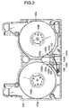
- Fig. 2 is a plan view showing a detailed relationship between a reel brake 120A and the tape reels 103.
- the upper case 101, upper reels 103a of the tape reels 103 and the tape-like medium are removed therefrom.
- the reel brake 120A is slidably disposed on the tape reels 3 side in the lower case 102.
- guided portions 122b of pawls 122 of the reel brake 120A engage guide grooves 102b on the lower case 102, respectively, and the reel brake 122 slides along the guide grooves 102b.
- the reel brake 120A is biassed toward the tape reels 103 side by means of a spring 109.
- teeth 103d are formed in outer circumferences of the lower flanges 103a of the tape reels 103 and when the tape cassette is not in use, the reel brake is put in a state shown in Fig. 2 in which the distal portions 122a of the pawls 122 of the reel brake 120A enter between the teeth 103d of the lower flanges 103a, respectively, whereby the tape reels 103 are locked, idle rotation of the tape reels 103 being thereby prevented.
- the reel brake 120A is moved to a rear side of the cassette against a biassing force of the spring 109 to thereby release the engagement between the pawls 122 and the teeth 103d of the lower flanges 103a, the tape reels 103 being thereby put in a rotatable state.
- Figs. 3A and 3B are perspective views showing the details of the reel brake 120A, Fig. 3A being a view as seen from the front side, and Fig. 3B being a view as seen from the rear side of the reel brake 120A.
- the reel brake 120A comprises a main body portion 121, arms 126 provided so as to protrude outwardly from rear portions on left and right sides of the main body portion 121, hinge portions 124 provided at distal ends of the respective arms 126 and pawls 122 connected to the arms 126 via the hinge portions 124, respectively.
- this pawl 122 constituted by a distal end portion 122a adapted to engage the teeth 103d of the tape reel 103, a guided portion 122b adapted engage a guide groove 102b formed in the lower case 102 and a root portion 122c.
- a regulating rib formed by extending rearward a portion of the root portion 122c which is close to the vicinity of the hinge portion 124 constitutes a regulating portion 123 for regulating the unnecessary rotation (excessive rotation) of the pawl 122.
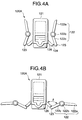
- Figs. 4A and 4B are plan views of the reel brake 120A, Fig. 4A showing a state in which the reel brake is in normal use, and Fig. 4B showing a state in which the pawls 122 are rotated excessively. Then, after they are formed, the reel brakes 120A are received in volume as a part constituting the tape cassette in a box or the like for transportation, and in assembling they are transferred into a part feeder. When this happens, there may be a risk of the pawls 22 being rotated excessively through entanglement of the reel brakes 20A in one another. As shown in Fig.
- the length of the regulating portions 123 needs to be sized such that even when it is received inside the tape cassette the regulating portion does not interfere with other members. Furthermore, a maximum rotating angle of the pawl 122 can easily be set by adjusting the position of the hinge portion 124 for connecting the root portion 122c of the pawl 122 with the distal end of the arm 126.
- the maximum rotating angle of the pawls 122 may preferably be equal to or less than about 100 degrees.
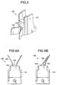
- Fig. 5 is a perspective view showing a second embodiment of the present invention.
- Figs. 6A and 6B are plan views of the reel brake 130 shown in Fig. 5, in which Fig. 6A shows a state in which the reel brake is in normal use and Fig. 6B shows a state in which a pawl 132 is rotated.
- a regulating portion 133 is constituted by a regulating rib provided on the front portion of a main body 131 and having a semi-circular cross-section and is disposed between a pair of hinge portions 134 and a pair of pawls 132.
- the pawl 132 is provided via the hinge portion 134 in the vicinity of a position where the regulating portion 133 of the main body 131 is provided.
- the first aspect of the present invention even if the pawls are rotated excessively when the reel brakes are transported or transferred into an automatic assembling machine, since a rotation exceeding a certain angle is prevented by the regulating portions, it is possible to prevent the breakage of the hinge portion or loss of a lock function that would be caused when the hinge portion is cut broken while a tape cassette is in use which has mistakenly incorporated therein a reel brake which happens to have a hinge portion having caused therein a cut.
- FIG. 7 is an exploded perspective view showing a tape cassette (DVC) according to the mode of operation of the present invention.
- a case main body comprises an upper case 201 and a lower case 202.
- a pair of tape reels 203 around which a tape-like medium (magnetic tape) 204 for recording information is wound are rotatably received in the case main body.
- a spring 212 is attached to an internal surface of the upper case 201 for pressing the tape reels 203 downwardly.
- the tape reel 203 comprises a lower flange 203a formed integrally with a hub portion 203b and a transparent upper flange 203c secured to an upper surface of the hub portion 203b by means of welding or the like.
- the tape-like medium 204 is disposed such that it comes out of an end of a front side of the lower case 202, passes through a front portion of the lower case 202 and returns into the case main body from the other end of the front side of the lower case 202.
- Attached to the front side of the upper case 201 are a substantially U-shaped front lid 205 adapted to freely open and/or close the front side of the case main body, an upper lid and a rear lid 207.
- the front lid 205 is rotatably attached to the upper case 201 and is biassed in a closing direction by means of a spring 211.
- the front lid 205 is attached to the upper lid 206, and the upper lid 206 is then attached to the rear lid 207.
- the tape-like medium 204 passing thorough the front portion of the lower case 202 is covered with these front lid 205, upper lid 206 and rear lid 207 for protection.
- the front lid 205 is rotated so as to be moved onto the upper lid 206, and in interlock with this movement of the front lid 205, the upper lid 206 and the rear lid 207 retire to predetermined positions, whereby the tape-like medium 204 situated at the front portion of the lower case 202 is then exposed.
- a fan-shaped opening 201a is formed in the upper case 201, and a flat-plate like window member 213 formed of a transparent resin is secured to an internal side of an area of the upper case 201 including this opening 201a.
- the tape-like medium 204 can be visualized by this window member 213 through the transparent upper flange 203c with respect, for instance, to the remaining amount thereof.
- Figs. 8A and 8B are perspective views showing the details of a reel brake 208, respectively, seen from the front side and rear side of the reel brake.
- Pawls 208a for engaging teeth 203d formed in the tape reels 203 are provided on left and right sides of a main body 208a of the reel brake 208.
- This pawl 208c is connected to the main body 208a via a thinned hinge portion 208b and can freely rotate via this hinge portion 208b.
- a guide shaft 208d is provided on the pawl 208c for engagement with the lower case 202 side.
- a projecting convex portion 208e is provided on a back of the main body 208e at an upper end corner thereof. This convex portion 208e is intended to prevent the disengagement of the main body 208e from a spring 209. Furthermore, a gate portion 208f is provided on a front of the main body 208e at a centrally upper portion thereof. Thus, the provision of the gate portion 208f at the central position on the front of the main body 208e provides a good balance in resin flow at the time of molding to thereby improve the moldability of the thinned hinge portions 208b.
- Fig. 9 is a plan view showing in detail a state in which the reel brake 208, the spring 209 and the tape reels 203 are mounted on an internal surface side of the lower case 202.
- the reel brake 208 is disposed centrally rearward inside the lower case 202 and is biassed by the spring 9 toward a tape reels 203 side.
- the spring 209 presses against the back of the main body 8e of the reel brake 208 and the convex portion 208e provided on this back prevents the disengagement of the spring 209 from the main body 208a.
- guide grooves 202c are formed on the lower case 202, and the guide shafts 208d of the reel brake 208 engage these guide grooves 202c of the lower case 202, whereby the reel brake 208 slides along the guide grooves 202c toward/away from the tape reels 203.
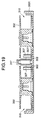
- Figs. 10A and 10B show a relationship between the reel brake 208 and a position regulating wall 202b of the lower case 202, in which Fig. 10A is a plan view and Fig. 10B is a section corresponding to a section taken along a plane B-B of Fig. 10A and the section includes the upper case 201.
- Fig. 205 shows a state in which the engagement between the reel brake 208 and the tape reels 203 are released from the state shown in Figs. 10A and 10B.
- the position regulating wall 202b is provided on the lower case 202 in such a manner as to confront the front of the main body 208a of the reel brake 208.
- the front of the main body 208a of the reel brake 208 is brought into abutment with the position regulating wall 202b.
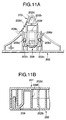
- a run off portion 202b shaped as a groove notched in a substantially U-shape from above is formed in a central portion of the position regulating wall 202b.
- the gate portion 8f of the reel brake 208 is disposed such that it fits in the notched portion 202d in the position regulating wall 202b when the reel brake 208 is brought into abutment with the position regulating wall 202b. Therefore, since the gate portion 8f of the reel brake 208 does not directly abut with the position regulating wall 202b, even if a projection (the remains of the gate) remains on the gate portion 208f, there is no chance of the sliding of the reel brake 208 being checked before the front of the main body 208a of the reel brake 208 is brought into close contact with the position regulating wall 202b.
- the position regulating wall 202b is constituted by a rib-like member provided on the lower case 202, but the configuration thereof is not limited to a wall-like configuration but any configuration may be used provided that it allows the front of the main body 208a of the reel brake 209 to abut therewith.
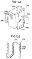
- Figs. 12A and 12B show a reel brake for a tape cassette according to a fourth embodiment of the present invention.
- Fig. 12A is a perspective view as seen from a front side of the reel brake
- Fig. 12B is a sectional view taken along a vertical line at a central portion of the reel brake.
- the second embodiment is different from the third embodiment in that a recessed portion 208g is formed by lowering a peripheral portion of the gate portion 208f in a step-like fashion.
- the depth of this recessed portion 208g needs to be deeper than a height of a projecting resin that remains at the gate portion 208f. With this construction, there is no need to form the notched portion 202d in the position regulating wall 202b of the lower case 202.
- the third embodiment is preferable to the fourth embodiment from the viewpoint of uniformity of thickness.
- the interference between the gate portion of the reel brake and the position regulating portion of the case main body can be prevented while the moldability of the reel brake is maintained, a secure engagement between the reel brake and the tape reels can be effected when the tape cassette is not in use.
- the thickness of the reel brake can be uniformed and the interference between the gate portion of the reel brake and the position regulating portion of the case main body can be prevented.
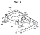
- a tape cassette according to the fifth embodiment comprises a pair of tape reels 302 around which a tape 301 is wound rotatably received in a case comprising upper and lower cases 303, 3031, the tape 1 being constructed to extend from one of the tape reels 302, pass through a front of the case and be wound up around the other tape reel 302, an opening 304 formed for allowing the tape 301 extending along the front of the case to be exposed therefrom, a lid member comprising a front lid 305 for covering a front of the tape 301 situated inside the opening 304, an upper lid 3051 for covering an upper surface of the tape and a rear lid 3052 for covering a back of the tape and adapted to be freely opened and/or closed by means of a lid opening and/or closing mechanism, tape exit and entrance 306 provided for pulling out the tape 301 and a reel brake member 317 comprising a pair of arms 307 each having a brake pawl 371 for suppressing the
- the reel brake member 317 has the arms 307 disposed so as to be connected to sides of a main body thereof at hinge portions 3072, which arms each have the brake pawl 3071 at a distal end thereof.
- Pin-like projections 3073, 3074 are provided at substantially intermediate positions between the brake pawl 3071 of the arm 307 and the hinge portion 3072, and the arms are pushed forward (to the tape reels side) by means of springs 314 thereat at all times so that the brake pawls 3701 are constructed so as to engage the teeth 3021 of the tape reels 302, whereby the tape reels 302 are prevented from rotating.
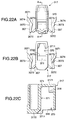
- the reel brake member 317 has an opening hole portion 370 for insertion of the brake release member P on a device side, and a guide recessed portion 372 for guiding the brake release member P is formed in a central portion of an abutment side wall portion 371 of the brake release member in the opening hole portion 370.
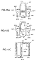
- This guide recessed portion 372 is formed in a vertical direction in the abutment side wall portion 371 of the brake release member P in the center of the opening hole portion 370, and an internal surface of the guide recessed portion 371 is formed into a U-shaped groove having a curved surface (Figs. 14A, 14B 15A, 15B and 15C).
- a V-shaped groove having a relatively large angle may be used instead.
- an inclined surface 3711 is formed on a lower side of the abutment side wall portion 371 of the brake release member P and formed on an upper side thereof is a vertical surface 3712.
- both sides of the guide recessed portion 372 through which the brake release member P is fittingly inserted are formed into flat surface portions.
- the guide recessed portion 372 formed in this vertical surface 3712 is formed so as to extend to a position into which the brake release member P is caused to penetrate. Then, the brake release member P on a device side is inserted from the opening portion 313 formed in the lower case 3031, whereby the reel brake member 317 having the opening hole portion 370 facing the opening portion 313 is moved rearward against the spring force of the spring 314, whereby the brake is released.
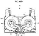
- Figs. 17A, 17B, 18A and 18B show the opening portion 313 and the regulating wall portions 309 inside the lower case 3031 at positions where the reel brake member 317 is attached, and the brake releasing member P penetrates into the opening hole portion 370 in the reel brake member 317 through this opening portion 313.
- Figs. 17A and 17B show the movement of the reel brake member 317 between the regulating wall portions 309 inside the case, in which Fig. 17A shows a brake state and Fig. 17B shows a brake released state.
- the brake release member P has an inclined surface on an upper surface thereof as shown in Figs. 20A and 20B, and with a diameter of a certain magnitude, the brake can be released without relative movement of the brake release member P and the case.
- brake release members of various diameters including that shown in Fig. 20C can be used and if both sides of the guide recessed portion 307 is left flat on both sides thereof, a brake release member having a square pole like shape as shown in Fig. 20B can also conveniently be used.
- the aforesaid brake pawl 3071 comprises the projections 3073, 3074 provided on the arm 307 of the reel brake member 317 and the regulating wall portions 309, 3103 provided on the internal surface of the case in such a manner as to protrude therefrom so as to confront the projections 3073, 3074 on both sides thereof for regulating the sliding of the arms 307 of the reel brake member 317.
- the regulating wall portion 309 for regulating the movement of the arm 307 is constituted by the linear guide rib 309 oriented toward the back side of the case and the outwardly curved guide rib oriented toward the front side of the case.
- the brake pawl 3071 is deployed so as to engage the teeth 3021 of the tape reel 302, whereby the rotation of the tape reel 302 in a direction in which the tape is loosened is prevented, while in an opposite direction the brake pawls 3071 are guided by the linear guide paths to move toward a center between the two arms 307 while approaching each other.
- the projections 3074 of the arms 307 comes into collision with the regulating wall portions 3103 to make the brake pawls 3071 operate in a closing direction.
- the brake pawls 3071 of the reel brake member 317 are guided from the curved guide paths to the linear guide paths of the regulating wall portions 309 for movement and then withdraw quickly from the reel areas 310. Then, the projections 3074 come into collision with the regulating wall portions 3103 so as to be guided thereby, and the brake pawls 3071 are then closed, thereby allowing the tape reels 302 to freely rotate.
- the reel brake member 317 constitutes a regulating mechanism comprising the opening hole portion 370 functioning as the brake release operating portion exposed from the opening portion 313 formed in the lower case 331, the projections 3073, 3074 provided on the arms 307 for regulating the movement of the arms 307 of the reel brake member 317 in the brake releasing direction, the regulating wall portions 309, 3103 provided on the internal surface of the case in such a manner as to protrude therefrom so as to confront the projections 3073, 3074 on both sides thereof and oriented so as to face the inside and outside of the arms 307 for regulating the sliding of the arms 307 of the reel brake member 317 for further securement of the regulation.
- the regulating wall portions 309 are provided on the lower case 3031 in such a manner as to protrude from a position where the movement of the brake arms 307 on the sides of the brake releasing opening portion 313 is regulated and to extend along partition walls 3101 in the reel areas 310, and the reel brake member 317 is operated by the brake releasing member P of the recording and reproducing device such as a cam rod.
- the brake pawls 3071 are allowed to move to a position where they are not allowed to disengage from the teeth 3021 on the outer circumferences of the lower flanges of the tape reels 302 when an impact is applied thereto when the tape cassette is not in use, and any further movement of the arms 307 of the reel brake member 317 may be regulated by the regulating wall portions 309.
- the reel brake member 317 is disposed between the pair of tape reels 302 at a position closer to a side opposite to the side where the opening portion 304 is formed for exposing the tape 301 therefrom and has the brake pawls 371 positioned at the distal ends of the pair of arms 307 for locking in the teeth 321 provided on the outer circumferences of the lower flanges of the tape reels 302 and the brake release operating portion provided with the inclined surface facing the opening portion 313 into which the brake release member P of the recording and reproducing device is inserted.
- the reel brake member 317 is provided such that it more smoothly slides for movement between the outer circumferential ribs 3101 of the partition walls of the pair of reel areas that are provided on the case in such a manner as to protrude therefrom.
- the brake pawl 3071 of the reel brake member 317 is constructed so as to be resiliently deformed via the arm 307 at the recessed and thinned resilient hinge portion 3072 and is biassed by the spring 314 in the direction in which it is brought into engagement with the teeth 3021 provided on the outer circumference of the lower flange of the tape reel.
- the thinned hinge portion 3072 provides an impact absorption effect through resilient deformation.
- the brake pawls 3071 are deployed outwardly by virtue of a restoring force and engage the regulating wall portions 309 of the case in such a manner as to be hooked thereon while maintaining the engagement with the teeth 321 on the outer circumferences of the lower flanges of the tape reels 302 to thereby restrict the movement of the arms 307 of the reel brake member 317.
- the brake pawls 3071 and the teeth 3021 on the tape reels 302 are in engagement with each other and such an engagement is constructed so as not to be disengaged.
- the regulating wall portion 309 is constructed so as to prevent the arm 307 of the reel brake member 317 from deflecting inwardly of the brake so as to prevent in turn the brake pawl 3071 from disengaging from the reel area and the reel brake member 317 is constructed such that the arms 307 of the reel brake member 317 are closed inwardly at a position near the brake releasing position so as to disengage the brake pawls from the reel areas 310.
- the regulating wall portion 309 for regulating the movement of the arm 307 of the reel brake member 317 is formed into a curved configuration in which the front thereof is expanded to both sides.
- the engagement with the tape reels can be disengaged at all times for free rotating operation of the reels. It is preferable to have a brake construction in which enven when the reel brake member 317 moves and approaches the brake releasing position, the brake pawls 3071 operate so as to quickly move in a radial direction of the tape reel 302 to thereby perform a secure brake operation so that the tape becomes free of a looseness.
- the regulating wall portions 309, 3103 for regulating the movement of the arms 307 are provided on the lower case 3031, but they may be provided on the upper case 303.
- a mode is effective in which the brake pawls 3071 are biassed in a direction in which the tape is wound up tightly.
- reference numeral 311 denotes a position regulating rib
- reference numeral 320 denotes a spring for pressingly support the tape reels 302.
- Reference numerals 21, 22, 323 and 324 denote, respectively, a lid lock, a plug, an MIC detecting portion, and an optical cover.
- the present invention provides a tape cassette comprising a pair of tape reels around which a tape is wound rotatably received in a case, the tape being disposed so as to extend from one of the tape reels through a front of the case to the other tape reel to be wound up therearound, and a reel brake member having brake pawls for suppressing the rotation of the tape reels and provided so as to freely slide for engagement with and disengagement from teeth of said tape reels for braking operation and brake releasing operation, respectively, the reel brake member being biassed by a spring toward a tape reels side, wherein a main body of the reel brake member comprises an opening hole portion for insertion of a brake release member provided on a device side, and wherein a guide recessed portion is formed at a center of an abutment side wall portion of the brake release member within the opening hole portion for guiding the brake release member.
- the tape cassette of the present invention constructed as described above, even when there are available on the device side different devices having different brake release members, it is possible to press, at all times, for operation a central portion of a brake release member in use to effect a smooth brake release operation.
- the normal brake function can also be maintained and there is caused no problem in using.
- the reel brake is prevented from being disengaged, and the production of a looseness of a tape can also be prevented. This helps prevent the generation of damage to a tape due to a cassette failure that would happen when it is mounted for use in a recording and reproducing device, whereby a highly reliable brake operation can be obtained.
- the tape cassette according to the present invention can be used with a recording and reproducing device adapted to use a conventional tape cassette without any modification.
- the tape cassette of the present invention can be used for various types of recording and reproducing devices without requiring a change in the type of a device available.
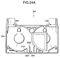
- a tape cassette according to the sixth embodiment comprises a pair of tape reels 302 around which a tape 301 is wound rotatably received in a case comprising upper and lower cases 303, 3031, the tape 301 being constructed to extend from one of the tape reels 302, pass through a front of the case and be wound up around the other tape reel 302, an opening 304 formed for allowing the tape 301 extending along the front of the case to be exposed therefrom, a lid member comprising a front lid 305 for covering a front of the tape 301 situated inside the opening 304, an upper lid 3051 for covering an upper surface of the tape and a rear lid 3052 for covering a back of the tape and adapted to be freely opened and/or closed by means of a lid opening and/or closing mechanism, tape exit and entrance 306 provided for pulling out the tape 301 and a reel brake member 317 comprising a pair of arms 307 each having a brake pawl 3071 for
- the reel brake member 317 has the arms 307 disposed so as to be connected to sides of a main body thereof at hinge portions 3072, which arms each have the brake pawl 3071 at a distal end thereof.
- Pin-like projections 3073, 3074 are provided at substantially intermediate positions between the brake pawl 3071 of the arm 307 and the hinge portion 3072, and the arms are pushed forward by means of springs 14 thereat at all times so that the brake pawls 3071 are constructed so as to engage the teeth 3021 of the tape reels 302, whereby the tape reels 302 are prevented from rotating. (see Fig. 13)
- an opening hole portion 370 is formed in a lower surface 3172 of the main body of the reel brake member 317 for a brake release maneuvering member P provided on a device side to be inserted thereinto.
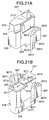
- the main body of the reel brake member further comprises an upper surface portion 3171 and a lower surface portion 3172 which are adapted to slide over internal sides of the upper and lower cases 303, 3031, and recessed portions 318 are formed on sides of the front of the upper surface portion 3171 at positions corresponding to outer circumferential edges of the tape reels.
- a butt recessed portion 319 is formed in the lower surface portion 3172 on the front side thereof in such a manner as to correspond to a holding rib 3102 provided on a front side of a reel brake sliding area on the lower case along a tape reel receiving area 310 (Figs. 21A to 23B).
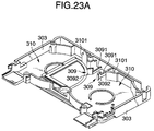
- regulating wall portions 309 for regulating the sliding of the arms 307 of the reel brake member 317 are provided on the internal surfaces of the upper and lower cases 303, 3031 in such a manner as to protrude therefrom, and the regulating wall portions 309 each comprise a linear guide rib 3091 oriented toward a back side of the case and a curved guide rib 3092 provided so as to extend outwardly toward the front side of the case.
- the curved guide ribs 3092 are formed higher than the linear guide ribs 3091 (Figs. 23A to 24B).
- an abutment side wall portion 371 for the brake releasing member P provided on a device side is formed in the opening hole portion 370 into which the brake releasing member P is inserted.
- This abutment side wall portion 371 for the brake releasing member has an inclined surface 3711 formed on a lower side thereof and a vertical surface 3712 on an upper side thereof, and a flat surface portion is formed on a side along which the brake releasing member P is fittingly inserted, but as required a guide recessed portion (not shown) may be formed to a position to which the brake releasing member P is allowed to penetrate.
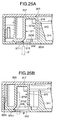
- Figs. 25A to 26B the opening portion 313 and the regulating wall portions 309 are provided on the lower case 3031 at positions where the reel brake member 317 is attached, and the brake releasing member P penetrates into the opening hole portion 370 in the reel brake member 317 through this opening portion 313.
- Figs. 25A and 25B show the movement of the reel brake member 317 between the regulating wall portions 309 inside the case, in which Fig. 25A shows a brake state and Fig. 25B shows a brake released state.
- the aforesaid brake pawl 3071 comprises the projections 3073, 7304 provided on the arm 307 of the reel brake member 317 and the regulating wall portions 309, 3103 provided on the internal surface of the case in such a manner as to protrude therefrom so as to confront the projections 3073, 3074 on both sides thereof for regulating the sliding of the arms 307 of the reel brake member 317.
- the regulating wall portion 309 for regulating the movement of the arm 307 is constituted by the linear guide rib 3091 oriented toward the back side of the case and the outwardly curved guide rib 3092 oriented toward the front side of the case.
- the brake pawl 3071 is deployed so as to engage the teeth 3021 of the tape reel 302, whereby the rotation of the tape reel 302 in a direction in which the tape is loosened is prevented, while in a rearward direction of the cassette the brake pawls 3071 are guided by the linear guide paths to move toward a center between the two arms 307 while approaching each other.
- the projections 3074 of the arms 307 comes into collision with the regulating wall portions 3103 to make the brake pawls 3071 operate in a closing direction.
- the brake pawls 371 of the reel brake member 317 are guided by the linear guide paths so as to move along the regulating wall portions 3103 and then withdraw quickly from the reel areas 310. Then, the projections 3074 come into collision with the regulating wall portions 3103 so as to be guided thereby, and the brake pawls 371 are then closed, thereby allowing the tape reels 302 to freely rotate.
- the reel brake member 317 constitutes a regulating mechanism comprising the opening hole portion 370 functioning as the brake release operating portion exposed from the opening portion 313 formed in the lower case 3031, the projections 3073, 3074 provided on the arms 307 for regulating the movement of the arms 307 of the reel brake member 317 in the brake releasing direction, the regulating wall portions 309, 3103 provided on the internal surface of the case in such a manner as to protrude therefrom so as to confront the projections 3073, 3074 on both sides thereof and oriented so as to face the inside and outside of the arms 307 for regulating the sliding of the arms 307 of the reel brake member 317 for further securement of the regulation.
- the regulating wall portions 309 are provided on the lower case 3031 in such a manner as to protrude from a position where the movement of the brake arms 307 on the sides of the brake releasing opening portion 313 is regulated and to extend along partition walls 3101 in the reel areas or locking ribs, and the brake pawls 3071 are provided at positions away by a distance over which the pawls can move in a state in which the pawls are in engagement with the teeth 3021 on the outer circumferences of the lower flanges of the tape reels 302, whereby the reel brake member 317 is operated by the brake releasing member P of the recording and reproducing device such as a cam rod.
- the brake pawls 3071 are allowed to move to a position where they are not allowed to disengage from the teeth 3021 on the outer circumferences of the lower flanges of the tape reels 302 when an impact is applied thereto when the tape cassette is not in use, and any further movement of the arms 7 of the reel brake member 317 may be regulated by the regulating wall portions 309.
- the reel brake member 317 is disposed between the pair of tape reels 302 at a position closer to a side opposite to the side where the opening portion 304 is formed for exposing the tape 301 therefrom and has the brake pawls 3071 positioned at the distal ends of the pair of arms 307 for locking in the teeth 3021 provided on the outer circumferences of the lower flanges of the tape reels 302 and the brake release operating portion provided with the inclined surface facing the opening portion 313 into which the brake release member P of the recording and reproducing device is inserted.
- the reel brake member 317 is provided such that it more smoothly slides for movement between the outer circumferential ribs 3101 of the partition walls of the pair of reel areas that are provided on the case in such a manner as to protrude therefrom.
- the brake pawl 3071 of the reel brake member 317 is constructed so as to be resiliently deformed via the arm 307 at the recessed and thinned resilient hinge portion 3072 and is biassed by the spring 314 in the direction in which it is brought into engagement with the teeth 3021 provided on the outer circumference of the lower flange of the tape reel.
- the thinned hinge portion 3072 provides an impact absorption effect through resilient deformation.
- the brake pawls 3071 are deployed outwardly by virtue of a restoring force and engage the regulating wall portions 309 of the case in such a manner as to be hooked thereon while maintaining the engagement with the teeth 3021 on the outer circumferences of the lower flanges of the tape reels 302 to thereby restrict the movement of the arms 307 of the reel brake member 317.
- the brake pawls 3071 and the teeth 3021 on the tape reels 302 are in engagement with each other and such an engagement is constructed so as not to be disengaged.
- the regulating wall portion 309 is constructed so as to prevent the arm 307 of the reel brake member 317 from deflecting inwardly of the brake so as to prevent in turn the brake pawl 3071 from disengaging from the reel area and the reel brake member 317 is constructed such that the arms 307 of the reel brake member 317 are closed inwardly at a position near the brake releasing position so as to disengage the brake pawls from the reel areas 310.
- the regulating wall portion 309 for regulating the movement of the arm 307 of the reel brake member 317 is formed into a curved configuration in which the front thereof is expanded to both sides, and another regulating wall portion 309 may be provided on the upper case 303 at a position confronting the regulating wall portion 309 on the lower case 3031, the regulating wall portion 309 on the upper case being made higher than the lower case 3031.
- the engagement with the tape reels can be disengaged at all times for free rotating operation of the reels. It is preferable to have a brake construction in which enven when the reel brake member 317 moves and approaches the brake releasing position, the brake pawls 3071 operate so as to quickly move in a radial direction of the tape reel 302 to thereby perform a secure brake operation so that the tape becomes free of a looseness.
- the regulating wall portions 309, 3103 for regulating the movement of the arms 7 are provided on the lower case 3031, but they may be provided on the upper case 303.
- a mode is effective in which the brake pawls 307 are biassed in a direction in which the tape is wound up tightly.
- the guide wall portions 309 with which the arms 307 of the reel brake member 317 are brought into sliding abutment are provided continuously with the outer circumferential ribs 3101 provided along the tape reel receiving areas 10, and holding ribs 3102 are provided at a substantially central position between the tape reel receiving areas 310 in such a manner as to protrude therefrom and are disposed so as to be connected to positioning ribs 311 provided on the lower case 3031 in such a manner as to protrude therefrom.
- the opening portion 313 for insertion of a brake releasing pin is formed at a portion of the lower case 3031 where the reel brake member 317 is disposed, and the brake holding ribs 3102 are formed on the front side of this opening portion 313. Furthermore, the position regulating walls 311 are provided forwardly of the brake holding ribs for regulating the forward position of the brake member 317.
- the regulating wall portions 309 for the reel brake member 317 are formed on the sides of the opening portion 313 on the rear side of the tape cassette.
- the distally expanded curved guide ribs 3092 are provided on the front side of the linear guide ribs 3091 and ribs for closing the brake pawls 3071 are provided on the outer sides of the brake pawls 3071.
- the recessed portion 319 in the lower surface portion 3172 of the reel brake member 317 is constructed so as to slide over the holding ribs 3102 on the lower case 303. Since the holding ribs 102 are higher than the thickness of the lower flange, even if the tape reels 302 are moved inside the case, the lower flanges are only brought into abutment with the holding ribs 3102, and there is no chance for them to come into abutment with the reel brake member 317. Similarly, the recessed portion 318 in the upper surface portion 3171 is configured so as not to be brought into abutment with the upper flange.
- the regulating wall portions 309 guide only the rear portion of the reel brake member 317 at the brake position.
- the brake main body can rotate in transverse directions, and this allows the reel brake member 317 to move so as to follow the movement of the tape reels 302, a more reliable brake mechanism being thereby provided.
- the projections 3073, 3074 provided on the arms 307 each having the brake pawl 3071 provided thereon in the brake state, the projections 3073 abut with the curved guide ribs 3091, whereby the brake pawls 3071 are deployed so as to maintain a secure brake state, and in the brake released state, the projections 3074 abut with the regulating wall portions 3103, whereby the brake pawls 3071 are closed so as to securely be disengaged from the reel areas 310.
- the brake pawls 3071 are opened and/or closed by the projections 3073, 3074 formed on the reel brake member 317 and the regulating wall portions 309, 3103, but the ribs may be configured otherwise so that no projection is provided on the brake pawls 3071.
- the reason why there is a difference in level between the curved guide ribs 3092 for deploying the brake pawls 3071 on the lower case 3031 and the linear ribs 3091 or the curved guide ribs 3092 are taller than the linear ribs 3091 is because the brake pawls 3071 can be securely deployed. Even if the brake member performs an oscillating action when the reel brake member 317 is assembled, the root of the brake pawl (in the vicinity of the hinge portion) is brought into abutment with the stepped portion rearward of the curved guide ribs 3092, thus the stepped portion being useful in regulating the reel brake member such that no unnecessary oscillating movements are performed.
- reference numeral 320 denotes a spring for pressingly support the tape reels 302.
- Reference numerals 321, 322, 323 and 324 denote, respectively, a lid lock, a plug, an MIC detecting portion, and an optical cover.
- the reel brake member 317 is constructed as a brake mechanism comprising arms 307 via hinge portions 3072, which arms each have a brake pawl 3071 formed at a distal end thereof, arm portions 3075 provided on external surfaces of the arms 307 in such a manner as to protrude therefrom so as to replace one of the projections, which is the projection 3073, and constructed so as to correspond to outer circumferential ribs 101 formed on the lower case 3031 for abutment and locking.
- like reference numerals are given to portions like to those described in the previous embodiment, and a description thereof will be omitted.
- the projections 3073 of the arms 307 abut with and act on the regulating wall portions 10a so that the arms 307 can operate smoothly for the following operation of the reel brake member 317, whereby the free rotational operation of the tape reels 302 can be secured.
- the regulating wall portions 309 on the lower case 3031 guide the projections 3073 provided on the arms 307 of the reel brake member 317 so as to securely regulate the position of the reel brake member 317 at the rear portion thereof.
- the present invention provides a tape cassette comprising a pair of tape reels around which a tape is wound rotatably received in a case, the tape being disposed so as to extend from one of the tape reels through a front of the case to the other tape reel to be wound up therearound, and a reel brake member having brake pawls for suppressing the rotation of the tape reels and provided so as to freely slide for engagement with and disengagement from teeth of the tape reels for braking operation and brake releasing operation, respectively, the reel brake member being biassed by a spring toward a tape reels side, wherein a main body of the reel brake member comprises arms provided on sides thereof via hinge portions, each of the arms having a brake pawl provided on a distal end thereof, an opening hole portion formed therein for insertion of a brake release operating member provided on a device side, upper and lower surface portions adapted to abut with and slide over internal surfaces of upper and lower cases, recessed portions provided on sides of a front side of said upper surface portion at positions corresponding to outer circumfer
- the reel brake member that is biassed by virtue of a resilient force inside the case so as to engage the tape reels is restricted and regulated to the extent that the engagement of the brake pawls of the reel brake member is disengaged when the tape cassette is not in use with respect to the movable range of the reel brake, and even if an external force from a strong impact such as a drop impact is exerted, the reel brake is prevented from being disengaged, and the production of a looseness of the tape can be prevented.
Landscapes
- Packaging Of Annular Or Rod-Shaped Articles, Wearing Apparel, Cassettes, Or The Like (AREA)
Applications Claiming Priority (8)
| Application Number | Priority Date | Filing Date | Title |
|---|---|---|---|
| JP32920198 | 1998-11-19 | ||
| JP10329201A JP2000156065A (ja) | 1998-11-19 | 1998-11-19 | テープカセット用リールブレーキ |
| JP36700198 | 1998-12-24 | ||
| JP36700198A JP3492536B2 (ja) | 1998-12-24 | 1998-12-24 | テープカセット |
| JP11002868A JP2000207867A (ja) | 1999-01-08 | 1999-01-08 | テ―プカセット |
| JP286899 | 1999-01-08 | ||
| JP766399 | 1999-01-14 | ||
| JP00766399A JP3495936B2 (ja) | 1999-01-14 | 1999-01-14 | テープカセット |
Publications (2)
| Publication Number | Publication Date |
|---|---|
| EP1003172A2 true EP1003172A2 (fr) | 2000-05-24 |
| EP1003172A3 EP1003172A3 (fr) | 2005-01-19 |
Family
ID=27453734
Family Applications (1)
| Application Number | Title | Priority Date | Filing Date |
|---|---|---|---|
| EP99122768A Withdrawn EP1003172A3 (fr) | 1998-11-19 | 1999-11-16 | Cassette à bande |
Country Status (2)
| Country | Link |
|---|---|
| US (1) | US6446896B1 (fr) |
| EP (1) | EP1003172A3 (fr) |
Families Citing this family (1)
| Publication number | Priority date | Publication date | Assignee | Title |
|---|---|---|---|---|
| US6820275B2 (en) * | 2001-03-16 | 2004-11-16 | Fuji Photo Film Co., Ltd. | Disc cartridge with transparent windows |
Family Cites Families (24)
| Publication number | Priority date | Publication date | Assignee | Title |
|---|---|---|---|---|
| JPS58173073A (ja) | 1982-04-05 | 1983-10-11 | Mitsubishi Heavy Ind Ltd | シリンダ−の製造方法 |
| JPS60102780U (ja) | 1983-12-20 | 1985-07-13 | ソニー株式会社 | テ−プカセツト |
| JPS60120571U (ja) | 1984-01-18 | 1985-08-14 | ティーディーケイ株式会社 | テ−プカセツト |
| JPS60146974U (ja) | 1984-03-07 | 1985-09-30 | ティーディーケイ株式会社 | テ−プカセツト |
| DE8420207U1 (de) * | 1984-07-06 | 1984-11-29 | Basf Ag, 6700 Ludwigshafen | Bandkassette, insbesondere magnetbandkassette |
| EP0169514B1 (fr) * | 1984-07-21 | 1991-04-03 | Sony Corporation | Cassette à bande magnétique avec mécanisme de blocage des bobines |
| CA1233248A (fr) * | 1984-09-14 | 1988-02-23 | Sony Corporation | Cassette a bande magnetoscopique |
| CA1316894C (fr) | 1986-07-18 | 1993-04-27 | Yuji Iwahashi | Dispositif d'arret pour bobine de cassette a ruban magnetique |
| US4739949A (en) * | 1986-10-20 | 1988-04-26 | Lin Long Jin | Wheel locks for video tape cassettes |
| JP2600264B2 (ja) * | 1988-03-31 | 1997-04-16 | ソニー株式会社 | テープリールの回転防止装置 |
| US5056735A (en) * | 1989-08-04 | 1991-10-15 | Shape Inc. | Video cassette integral actuator/reel lock/spring |
| JPH03106587A (ja) | 1989-09-20 | 1991-05-07 | Fanuc Ltd | 多関節レーザロボット用アライメント装置及びその調整方法 |
| JP2979250B2 (ja) | 1991-01-09 | 1999-11-15 | 日立マクセル株式会社 | テープカートリッジ |
| JP3106587B2 (ja) | 1991-09-20 | 2000-11-06 | 株式会社日立製作所 | ディスクケースおよび光ディスク装置 |
| JPH05205437A (ja) * | 1992-01-27 | 1993-08-13 | Sony Corp | ビデオテープカセットのリールロック機構 |
| JPH0644733A (ja) * | 1992-07-24 | 1994-02-18 | Sony Corp | テープカセット |
| US5449124A (en) * | 1992-11-19 | 1995-09-12 | Sony Corporation | Reel lock mechanism for tape cassette |
| JP3351011B2 (ja) | 1993-03-15 | 2002-11-25 | ソニー株式会社 | テープカセット |
| JP3453855B2 (ja) * | 1994-07-15 | 2003-10-06 | ソニー株式会社 | リール用リールロック機構及びその組立方法 |
| US5505397A (en) * | 1994-07-22 | 1996-04-09 | Goff; Dewain R. | One-piece videocassette reel lock system |
| US5860611A (en) * | 1995-02-21 | 1999-01-19 | Tdk Corporation | Tape cassette and recording and reproducing apparatus |
| JP3473873B2 (ja) | 1995-03-23 | 2003-12-08 | 富士写真フイルム株式会社 | 磁気テープカセット |
| JP3570828B2 (ja) | 1996-10-03 | 2004-09-29 | Tdk株式会社 | テープカセット |
| JPH11203820A (ja) | 1997-11-12 | 1999-07-30 | Fuji Photo Film Co Ltd | 磁気テープカセット |
-
1999
- 1999-11-12 US US09/439,095 patent/US6446896B1/en not_active Expired - Fee Related
- 1999-11-16 EP EP99122768A patent/EP1003172A3/fr not_active Withdrawn
Also Published As
| Publication number | Publication date |
|---|---|
| EP1003172A3 (fr) | 2005-01-19 |
| US6446896B1 (en) | 2002-09-10 |
Similar Documents
| Publication | Publication Date | Title |
|---|---|---|
| US5596464A (en) | Locking assembly for a lid member of a tape cassette | |
| EP1003172A2 (fr) | Cassette à bande | |
| EP1083566A2 (fr) | Cassette à bande et moule pour sa fabrication | |
| US5860611A (en) | Tape cassette and recording and reproducing apparatus | |
| US5708546A (en) | Tape cartridge | |
| KR100292731B1 (ko) | 테이프 카셋트 | |
| EP0582206B1 (fr) | Cassette à bande | |
| US5689393A (en) | Magnetic disk cartridge having an opening for a magnetic head on a side thereof | |
| JP4663358B2 (ja) | 記録テープカートリッジ | |
| US4658981A (en) | Recording tape cartridge | |
| JP3141125B2 (ja) | テープカートリッジ | |
| US6430004B1 (en) | Tape cassette reel-locking spring with connection portion bent downwardly at midway portion thereof | |
| US5540399A (en) | Tape cassette | |
| JPH06103725A (ja) | テープカートリッジ | |
| EP0558066B1 (fr) | Cassette à bande magnétique | |
| US6338449B1 (en) | Tape cassette capable of easily installing and securing biasing member for reel brake | |
| JPH075593Y2 (ja) | テープカセット | |
| JP4865071B2 (ja) | リール | |
| EP1047071A2 (fr) | Cassette à bande | |
| KR100591481B1 (ko) | 테이프카트리지 | |
| JPS6349904Y2 (fr) | ||
| JP3378929B2 (ja) | テープカートリッジ | |
| JP2000156065A (ja) | テープカセット用リールブレーキ | |
| JP2001126439A (ja) | テープカセット | |
| JPH0845232A (ja) | テープカセット |
Legal Events
| Date | Code | Title | Description |
|---|---|---|---|
| PUAI | Public reference made under article 153(3) epc to a published international application that has entered the european phase |
Free format text: ORIGINAL CODE: 0009012 |
|
| AK | Designated contracting states |
Kind code of ref document: A2 Designated state(s): AT BE CH CY DE DK ES FI FR GB GR IE IT LI LU MC NL PT SE |
|
| AX | Request for extension of the european patent |
Free format text: AL;LT;LV;MK;RO;SI |
|
| PUAL | Search report despatched |
Free format text: ORIGINAL CODE: 0009013 |
|
| AK | Designated contracting states |
Kind code of ref document: A3 Designated state(s): AT BE CH CY DE DK ES FI FR GB GR IE IT LI LU MC NL PT SE |
|
| AX | Request for extension of the european patent |
Extension state: AL LT LV MK RO SI |
|
| 17P | Request for examination filed |
Effective date: 20050706 |
|
| RBV | Designated contracting states (corrected) |
Designated state(s): AT BE CH CY DE DK ES FI FR GB GR IE IT LI LU MC NL PT SE |
|
| AKX | Designation fees paid |
Designated state(s): DE ES FR GB IT |
|
| 17Q | First examination report despatched |
Effective date: 20060215 |
|
| STAA | Information on the status of an ep patent application or granted ep patent |
Free format text: STATUS: THE APPLICATION IS DEEMED TO BE WITHDRAWN |
|
| 18D | Application deemed to be withdrawn |
Effective date: 20070115 |