EP1003191B1 - Interrupteur magnétothermique - Google Patents
Interrupteur magnétothermique Download PDFInfo
- Publication number
- EP1003191B1 EP1003191B1 EP98203874A EP98203874A EP1003191B1 EP 1003191 B1 EP1003191 B1 EP 1003191B1 EP 98203874 A EP98203874 A EP 98203874A EP 98203874 A EP98203874 A EP 98203874A EP 1003191 B1 EP1003191 B1 EP 1003191B1
- Authority
- EP
- European Patent Office
- Prior art keywords
- lever
- breaker
- movable contact
- fact
- operating
- Prior art date
- Legal status (The legal status is an assumption and is not a legal conclusion. Google has not performed a legal analysis and makes no representation as to the accuracy of the status listed.)
- Expired - Lifetime
Links
- 230000033001 locomotion Effects 0.000 description 15
- 230000001419 dependent effect Effects 0.000 description 6
- 230000002860 competitive effect Effects 0.000 description 1
- 230000008878 coupling Effects 0.000 description 1
- 238000010168 coupling process Methods 0.000 description 1
- 238000005859 coupling reaction Methods 0.000 description 1
- 238000009413 insulation Methods 0.000 description 1
- 238000004519 manufacturing process Methods 0.000 description 1
- 239000000463 material Substances 0.000 description 1
- 239000002184 metal Substances 0.000 description 1
- 230000007935 neutral effect Effects 0.000 description 1
Images

Classifications
-
- H—ELECTRICITY
- H01—ELECTRIC ELEMENTS
- H01H—ELECTRIC SWITCHES; RELAYS; SELECTORS; EMERGENCY PROTECTIVE DEVICES
- H01H71/00—Details of the protective switches or relays covered by groups H01H73/00 - H01H83/00
- H01H71/10—Operating or release mechanisms
- H01H71/50—Manual reset mechanisms which may be also used for manual release
- H01H71/52—Manual reset mechanisms which may be also used for manual release actuated by lever
- H01H71/526—Manual reset mechanisms which may be also used for manual release actuated by lever the lever forming a toggle linkage with a second lever, the free end of which is directly and releasably engageable with a contact structure
-
- H—ELECTRICITY
- H01—ELECTRIC ELEMENTS
- H01H—ELECTRIC SWITCHES; RELAYS; SELECTORS; EMERGENCY PROTECTIVE DEVICES
- H01H2300/00—Orthogonal indexing scheme relating to electric switches, relays, selectors or emergency protective devices covered by H01H
- H01H2300/046—Orthogonal indexing scheme relating to electric switches, relays, selectors or emergency protective devices covered by H01H using snap closing mechanisms
- H01H2300/048—Snap closing by latched movable contact, wherein the movable contact is held in a minimal distance from the fixed contact during first phase of closing sequence in which a closing spring is charged
Definitions
- the present invention relates to a thermomagnetic circuit-breaker with means for adjusting the motion of the movable contacts.
- thermomagnetic circuit-breakers may feature, in accordance with the regulations in force, a so-called dependent closing movement, which in essence means that the movement of the movable contacts depends on the movement of an operating knob or lever.
- said operating knob brings the movable contact closer to the fixed contact; then, electrically coupling between contacts is achieved by means of a subsequent elastic thrust on the movable contact in order to increase the tightness of contact and generate the contact pressure.
- circuit breakers of this type With circuit breakers of this type, the interruption of a closing operation for any reason and at any angle of travel of the operating knob could happen when the movable contact has already reached a position close to the fixed contact or even is yet in contact with it without the necessary pressure; in this cases, damages to the contacts could occur.
- Thermomagnetic circuit-breakers have already been launched on the market that have a dependent operation in a first part until reaching a predetermined stop distance of the movable contact in relation to the fixed contact, said distance being then exceeded with a tripping movement that performs the closing.
- a further drawback is in addition constituted by the fact that the operating lever or knob and the operating lever need to have opposing directions of rotation, thus creating considerable manufacturing complications and significant limitations regarding the dimensions and positioning.
- thermomagnetic circuit-breaker with means for adjusting the motion of the movable contacts in which it is possible to predetermine a stop distance for the movable contacts in relation to the fixed contacts that is always constant and defined by the design geometry so that one always has a safety condition.
- a particular object of the invention is to provide a thermomagnetic circuit-breaker in which it is possible to guarantee a minimum insulation distance between the contacts when interrupting the closing operation for any reason at any angle of travel of the knob.
- Another object of the present invention is to provide a thermomagnetic circuit-breaker in which the minimum contact pressure is practically the same as the nominal pressure even with a slow closing operation, thus ensuring lower contact wear.
- a further object of the present invention is to provide a thermomagnetic circuit-breaker which can be used, in its general constructional lines, as a circuit-breaker with dependent operation if desired, offering the possibility, with the addition of an easily-installed part, of increasing the functionality of the circuit-breaker with the introduction of the predetermined stopping distance of the contacts before the closing tripping movement.
- thermomagnetic circuit-breaker with means for adjusting the motion of the movable contacts that can be easily obtained using common commercially-available elements and materials and that is, furthermore, competitive from a purely economic standpoint.
- thermomagnetic circuit-breaker comprising a moulded case containing a movable contact and a fixed contact, the movable contact being connected to an operating lever controlled by a trip lever and operatively associated to an operating knob, characterised by the fact that it comprises an auxiliary lever engageable with said movable contact to hold it at a predetermined distance from said fixed contact during closing operations, said auxiliary lever being operatively coupled with the operating knob to release the movable contact allowing completion of the closing operation.
- Document US 4 740 770 discloses a device according to the preamble of claim 1.
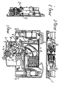
- thermomagnetic circuit-breaker includes a moulded case overall indicated by reference number 1 which substantially has a standardised conformation typical of thermomagnetic circuit-breakers for connection to omega-shaped bars.
- Movable electric contacts indicated by 2 for the phase contact and 3 for the neutral contact, are provided inside the moulded case 1.
- the movable contacts are connected to an operating lever 4 that is controlled by a trip lever 5 and associated with an operating knob or lever 7 by means of a U bolt 6.
- the movable contacts 2 and 3 are available for contact with corresponding fixed contacts 8 defined inside the moulded case.
- a spring associated to the trip lever 5 indicated overall by 10 acts between the operating lever 4 and the trip lever 5; said spring 10 has the distinctive feature of being of the hairpin type with an axial appendix 10a held in a corresponding seat of the trip lever 5 and a radial appendix 10b that engages with a catch projection 11.
- the projection 11 is defined on the operating lever 4 at the moment of assembly of the lever 5 and the operating lever 4 itself.
- the movable contacts 2 and 3 have contact springs, indicated by 15, also of the hairpin type, that interact with a catch projection 16 located on the operating lever and with an appendix 17 defined by the movable contact.
- thermomagnetic circuit-breaker features an opening release that operates by means of the relative rotation of the operating lever in relation to the trip lever 5; the operation can occur by means of the action of a thrust pin 18 connected to a relay 19 that acts on the trip lever, for example in case of a high fault current (short circuit).
- a bimetallic strip 20 is provided that acts on a thermal trip lever 21 in the event of an overload; this strip 20 transmits the movement to the trip lever.
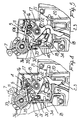
- the distinctive feature of the invention is constituted by the fact that an auxiliary lever 30 is provided that pivots alongside the axis of the operating lever and has the function of movably stopping the movable electric contacts during closing operations at a predetermined distance from the fixed contact 8.
- the auxiliary lever has a body 31 that terminates in a head 32 and defines, on the part facing the movable contacts, a recess 33 in which a prominence 34 of the movable contacts engages.
- the head 32 features a protuberance 35 that extends from the opposite side in relation to said recess 33 and is designed to interact with a cam 36 that is connected to the operating knob 7.
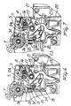
- the movable contacts are positioned at a distance from the fixed contact, and the prominence 34 is engaged with the auxiliary lever close to the pivoting zone; as illustrated, the lever 30, pushed by a spring 40, associated to the lever 30 itself, is held against the prominence 34 in a lower area of the recess 33.
- the rotation of the knob causes the operating lever to rotate at a speed dependent on that of the knob 7 by means of a U bolt 6, bringing the movable contacts close to the fixed contact 8 until stopping at a predetermined distance due to the engagement of the prominence 34 with a catch projection defined by the head 32 at the end of the recess 33.
- the pressure action applied is therefore substantially constant and, even in cases where slow operation is executed, the pressure applied is still substantially the same as the nominal pressure.
- a further aspect worthy of emphasis is constituted by the fact that the operating knob and the operating lever rotate in the same direction, thus significantly simplifying the structure of the device.
- auxiliary lever and related spring are elements that can be added to a thermomagnetic circuit-breaker that would behave like a traditional device without the presence of such a lever.
- the design and implementation of the cams together with the operating knob and auxiliary lever ensure that the movable contacts do not encounter obstacles in their opening travel that could be the cause of jamming or loss of performance in the event of a short circuit.
- a further important aspect is in addition constituted by the fact that the spring of the trip lever acts between the trip lever and the operating lever, thus having greater speed of response in use.
Landscapes
- Breakers (AREA)
- Thermally Actuated Switches (AREA)
- Electrophonic Musical Instruments (AREA)
- Thermotherapy And Cooling Therapy Devices (AREA)
Claims (8)
- Disjoncteur magnétothermique comprenant un boîtier moulé contenant un contact mobile (2,3) et un contact fixe (18), le contact mobile étant connecté à un levier d'actionnement commandé par un levier de déclenchement et associé fonctionnellement à un bouton d'actionnement (7), caractérisé en ce qu'il comprend un levier auxiliaire (30) pouvant s'engager avec ledit contact mobile pour le maintenir à une distance prédéterminée dudit contact fixe durant les opérations de fermeture, ledit levier auxiliaire étant couplé opérationnellement avec le bouton d'actionnement pour libérer le contact mobile et permettre la terminaison de l'opération de fermeture.
- Disjoncteur magnétothermique selon la revendication 1, caractérisé en ce que ledit levier auxiliaire possède un corps qui se termine par une tête qui définit, dans la partie située face audit contact mobile, un renfoncement dans lequel s'engage une saillie du contact mobile lui-même.
- Disjoncteur magnétothermique selon la revendication 2, caractérisé en ce que ladite tête comporte une protubérance qui s'étend à partir du côté opposé dudit renfoncement, ladite protubérance étant conçue pour interagir avec une came connectée au bouton d'actionnement.
- Disjoncteur magnétothermique selon l'une quelconque des revendications précédentes, caractérisé en ce qu'il comprend un ressort associé au levier auxiliaire, conçu pour presser le levier auxiliaire vers le contact mobile.
- Disjoncteur magnétothermique selon l'une quelconque des revendications précédentes, caractérisé en ce que ledit levier auxiliaire pivote le long de l'axe dudit levier d'actionnement.
- Disjoncteur magnétothermique selon l'une quelconque des revendications précédentes, caractérisé en ce que ledit bouton d'actionnement et ledit levier d'actionnement tournent dans le même sens.
- Disjoncteur magnétothermique selon l'une quelconque des revendications précédentes, caractérisé en ce qu'il comprend un ressort associé au levier de déclenchement qui interagit avec ledit levier de déclenchement et ledit levier d'actionnement.
- Disjoncteur magnétothermique selon la revendication 7, caractérisé en ce que ledit ressort associé au levier de déclenchement est un ressort en épingle à cheveux possédant un appendice axial qui peut être logé dans un siège défini par ledit levier de déclenchement et un appendice radial qui peut s'engager dans une projection d'entraînement définie sur ledit levier d'actionnement.
Priority Applications (4)
| Application Number | Priority Date | Filing Date | Title |
|---|---|---|---|
| EP98203874A EP1003191B1 (fr) | 1998-11-19 | 1998-11-19 | Interrupteur magnétothermique |
| AT98203874T ATE315832T1 (de) | 1998-11-19 | 1998-11-19 | Thermomagnetischer schutzschalter |
| ES98203874T ES2256914T3 (es) | 1998-11-19 | 1998-11-19 | Interruptor magnetotermico. |
| DE69833158T DE69833158T2 (de) | 1998-11-19 | 1998-11-19 | Thermomagnetischer Schutzschalter |
Applications Claiming Priority (1)
| Application Number | Priority Date | Filing Date | Title |
|---|---|---|---|
| EP98203874A EP1003191B1 (fr) | 1998-11-19 | 1998-11-19 | Interrupteur magnétothermique |
Publications (2)
| Publication Number | Publication Date |
|---|---|
| EP1003191A1 EP1003191A1 (fr) | 2000-05-24 |
| EP1003191B1 true EP1003191B1 (fr) | 2006-01-11 |
Family
ID=8234342
Family Applications (1)
| Application Number | Title | Priority Date | Filing Date |
|---|---|---|---|
| EP98203874A Expired - Lifetime EP1003191B1 (fr) | 1998-11-19 | 1998-11-19 | Interrupteur magnétothermique |
Country Status (4)
| Country | Link |
|---|---|
| EP (1) | EP1003191B1 (fr) |
| AT (1) | ATE315832T1 (fr) |
| DE (1) | DE69833158T2 (fr) |
| ES (1) | ES2256914T3 (fr) |
Families Citing this family (3)
| Publication number | Priority date | Publication date | Assignee | Title |
|---|---|---|---|---|
| DE102006051807B8 (de) * | 2006-11-03 | 2008-06-26 | Abb Ag | Elektrischer Schalter |
| DE102014107265B4 (de) * | 2014-05-22 | 2020-01-02 | Eaton Intelligent Power Limited | Schaltgerät |
| DE102014107266A1 (de) * | 2014-05-22 | 2015-11-26 | Eaton Industries Austria Gmbh | Schaltgerät |
Family Cites Families (4)
| Publication number | Priority date | Publication date | Assignee | Title |
|---|---|---|---|---|
| DE3031482A1 (de) * | 1980-08-21 | 1982-04-01 | Licentia Patent-Verwaltungs-Gmbh, 6000 Frankfurt | Schaltmechanismus fuer leitungsschutzschalter |
| FR2581791B1 (fr) * | 1985-05-13 | 1988-11-04 | Merlin Gerin | Mecanisme de fermeture manuelle brusque d'un appareil de coupure de courant |
| FR2589627B1 (fr) * | 1985-10-31 | 1988-08-26 | Merlin Gerin | Mecanisme de commande pour disjoncteur electrique a basse tension |
| FR2610760B1 (fr) * | 1987-02-10 | 1993-05-14 | Serd Soc Et Realisa Disjonct | Interrupteur automatique multipolaire basse-tension a commande manuelle |
-
1998
- 1998-11-19 ES ES98203874T patent/ES2256914T3/es not_active Expired - Lifetime
- 1998-11-19 AT AT98203874T patent/ATE315832T1/de not_active IP Right Cessation
- 1998-11-19 EP EP98203874A patent/EP1003191B1/fr not_active Expired - Lifetime
- 1998-11-19 DE DE69833158T patent/DE69833158T2/de not_active Expired - Lifetime
Also Published As
| Publication number | Publication date |
|---|---|
| ATE315832T1 (de) | 2006-02-15 |
| DE69833158D1 (de) | 2006-04-06 |
| EP1003191A1 (fr) | 2000-05-24 |
| DE69833158T2 (de) | 2006-08-31 |
| ES2256914T3 (es) | 2006-07-16 |
Similar Documents
| Publication | Publication Date | Title |
|---|---|---|
| US4392036A (en) | Low-voltage protective circuit breaker with a forked locking lever | |
| US4516098A (en) | Overcurrent protection switch | |
| US5982258A (en) | Tripping device for a circuit breaker equipped with an electrical fault indication | |
| EP3561849B1 (fr) | Disjoncteur | |
| US5831499A (en) | Selective trip unit for a multipole circuit breaker | |
| EP1003191B1 (fr) | Interrupteur magnétothermique | |
| EP1294005B1 (fr) | Amélioration d'un ensemble de lames de contact pour coupe-circuit | |
| US6642820B2 (en) | Protective switch | |
| CN101552161B (zh) | 全保护开关 | |
| EP0691031B1 (fr) | Disjoncteur a double rupture comportant une section secondaire amelioree | |
| US6262643B1 (en) | Mechanism for controlling an electrical circuit breaker | |
| US6867672B2 (en) | Switching device comprising a latching mechanism | |
| CA1253552A (fr) | Prevention de l'hesitation a la fermeture pour coupe-circuit miniatures actionnes manuellement | |
| JPH11213842A (ja) | 熱磁気回路遮断器 | |
| JP4154835B2 (ja) | 回路しゃ断器 | |
| EP1014415B1 (fr) | Disjoncteur | |
| MXPA98009636A (en) | Magnetoterm circuit breaker | |
| GB2376800A (en) | Multipole electrical switching device with latch | |
| US5918732A (en) | Power circuit breaker with a breaker mechanism and a breaker mechanism for a power circuit breaker with a lock for a low-voltage switch | |
| EP1412958B1 (fr) | Mecanisme cinematique pour dispositif de protection contre les baisses de tension et/ou d'interruption de courant | |
| JPH0136652B2 (fr) | ||
| EP1430499B1 (fr) | Disjoncteur automatique basse tension comprenant un nombre reduit de composants | |
| EP1805776B1 (fr) | Mecanisme destine a un interrupteur de securite | |
| KR200304675Y1 (ko) | 모터 보호용 차단기의 강제 트립장치 | |
| EP1054424B1 (fr) | Appareil électrique modulaire auxiliaire, notamment pour un disjoncteur ou similaire |
Legal Events
| Date | Code | Title | Description |
|---|---|---|---|
| PUAI | Public reference made under article 153(3) epc to a published international application that has entered the european phase |
Free format text: ORIGINAL CODE: 0009012 |
|
| AK | Designated contracting states |
Kind code of ref document: A1 Designated state(s): AT BE CH DE ES FR GB LI NL |
|
| AX | Request for extension of the european patent |
Free format text: AL;LT;LV;MK;RO;SI |
|
| 17P | Request for examination filed |
Effective date: 20001107 |
|
| AKX | Designation fees paid |
Free format text: AT BE CH DE ES FR GB LI NL |
|
| GRAP | Despatch of communication of intention to grant a patent |
Free format text: ORIGINAL CODE: EPIDOSNIGR1 |
|
| GRAS | Grant fee paid |
Free format text: ORIGINAL CODE: EPIDOSNIGR3 |
|
| RAP1 | Party data changed (applicant data changed or rights of an application transferred) |
Owner name: ABB SACE S.P.A. |
|
| GRAA | (expected) grant |
Free format text: ORIGINAL CODE: 0009210 |
|
| AK | Designated contracting states |
Kind code of ref document: B1 Designated state(s): AT BE CH DE ES FR GB LI NL |
|
| PG25 | Lapsed in a contracting state [announced via postgrant information from national office to epo] |
Ref country code: NL Free format text: LAPSE BECAUSE OF FAILURE TO SUBMIT A TRANSLATION OF THE DESCRIPTION OR TO PAY THE FEE WITHIN THE PRESCRIBED TIME-LIMIT Effective date: 20060111 Ref country code: LI Free format text: LAPSE BECAUSE OF FAILURE TO SUBMIT A TRANSLATION OF THE DESCRIPTION OR TO PAY THE FEE WITHIN THE PRESCRIBED TIME-LIMIT Effective date: 20060111 Ref country code: CH Free format text: LAPSE BECAUSE OF FAILURE TO SUBMIT A TRANSLATION OF THE DESCRIPTION OR TO PAY THE FEE WITHIN THE PRESCRIBED TIME-LIMIT Effective date: 20060111 Ref country code: BE Free format text: LAPSE BECAUSE OF FAILURE TO SUBMIT A TRANSLATION OF THE DESCRIPTION OR TO PAY THE FEE WITHIN THE PRESCRIBED TIME-LIMIT Effective date: 20060111 Ref country code: AT Free format text: LAPSE BECAUSE OF FAILURE TO SUBMIT A TRANSLATION OF THE DESCRIPTION OR TO PAY THE FEE WITHIN THE PRESCRIBED TIME-LIMIT Effective date: 20060111 |
|
| REG | Reference to a national code |
Ref country code: CH Ref legal event code: EP |
|
| REF | Corresponds to: |
Ref document number: 69833158 Country of ref document: DE Date of ref document: 20060406 Kind code of ref document: P |
|
| NLV1 | Nl: lapsed or annulled due to failure to fulfill the requirements of art. 29p and 29m of the patents act | ||
| REG | Reference to a national code |
Ref country code: ES Ref legal event code: FG2A Ref document number: 2256914 Country of ref document: ES Kind code of ref document: T3 |
|
| REG | Reference to a national code |
Ref country code: CH Ref legal event code: PL |
|
| ET | Fr: translation filed | ||
| PLBE | No opposition filed within time limit |
Free format text: ORIGINAL CODE: 0009261 |
|
| STAA | Information on the status of an ep patent application or granted ep patent |
Free format text: STATUS: NO OPPOSITION FILED WITHIN TIME LIMIT |
|
| 26N | No opposition filed |
Effective date: 20061012 |
|
| REG | Reference to a national code |
Ref country code: FR Ref legal event code: TP |
|
| REG | Reference to a national code |
Ref country code: FR Ref legal event code: PLFP Year of fee payment: 18 |
|
| PGFP | Annual fee paid to national office [announced via postgrant information from national office to epo] |
Ref country code: GB Payment date: 20151127 Year of fee payment: 18 Ref country code: DE Payment date: 20151127 Year of fee payment: 18 |
|
| PGFP | Annual fee paid to national office [announced via postgrant information from national office to epo] |
Ref country code: ES Payment date: 20151214 Year of fee payment: 18 Ref country code: FR Payment date: 20151127 Year of fee payment: 18 |
|
| REG | Reference to a national code |
Ref country code: DE Ref legal event code: R119 Ref document number: 69833158 Country of ref document: DE |
|
| GBPC | Gb: european patent ceased through non-payment of renewal fee |
Effective date: 20161119 |
|
| REG | Reference to a national code |
Ref country code: FR Ref legal event code: ST Effective date: 20170731 |
|
| PG25 | Lapsed in a contracting state [announced via postgrant information from national office to epo] |
Ref country code: FR Free format text: LAPSE BECAUSE OF NON-PAYMENT OF DUE FEES Effective date: 20161130 |
|
| PG25 | Lapsed in a contracting state [announced via postgrant information from national office to epo] |
Ref country code: GB Free format text: LAPSE BECAUSE OF NON-PAYMENT OF DUE FEES Effective date: 20161119 Ref country code: DE Free format text: LAPSE BECAUSE OF NON-PAYMENT OF DUE FEES Effective date: 20170601 |
|
| PG25 | Lapsed in a contracting state [announced via postgrant information from national office to epo] |
Ref country code: ES Free format text: LAPSE BECAUSE OF FAILURE TO SUBMIT A TRANSLATION OF THE DESCRIPTION OR TO PAY THE FEE WITHIN THE PRESCRIBED TIME-LIMIT Effective date: 20060111 |
|
| REG | Reference to a national code |
Ref country code: ES Ref legal event code: FD2A Effective date: 20180625 |
|
| PG25 | Lapsed in a contracting state [announced via postgrant information from national office to epo] |
Ref country code: ES Free format text: LAPSE BECAUSE OF FAILURE TO SUBMIT A TRANSLATION OF THE DESCRIPTION OR TO PAY THE FEE WITHIN THE PRESCRIBED TIME-LIMIT Effective date: 20161120 |