EP1003202B1 - Entladungslampe - Google Patents
Entladungslampe Download PDFInfo
- Publication number
- EP1003202B1 EP1003202B1 EP99308633A EP99308633A EP1003202B1 EP 1003202 B1 EP1003202 B1 EP 1003202B1 EP 99308633 A EP99308633 A EP 99308633A EP 99308633 A EP99308633 A EP 99308633A EP 1003202 B1 EP1003202 B1 EP 1003202B1
- Authority
- EP
- European Patent Office
- Prior art keywords
- reflector
- lamp body
- slits
- discharge lamp
- holes
- Prior art date
- Legal status (The legal status is an assumption and is not a legal conclusion. Google has not performed a legal analysis and makes no representation as to the accuracy of the status listed.)
- Expired - Lifetime
Links
- 125000006850 spacer group Chemical group 0.000 claims description 20
- 239000011521 glass Substances 0.000 claims description 12
- 239000002184 metal Substances 0.000 description 14
- 230000015572 biosynthetic process Effects 0.000 description 4
- 238000004880 explosion Methods 0.000 description 4
- 239000000919 ceramic Substances 0.000 description 3
- 230000000694 effects Effects 0.000 description 3
- 229920003023 plastic Polymers 0.000 description 3
- 239000004033 plastic Substances 0.000 description 3
- 238000009423 ventilation Methods 0.000 description 3
- 238000007664 blowing Methods 0.000 description 2
- 238000010276 construction Methods 0.000 description 1
- 238000001816 cooling Methods 0.000 description 1
- 238000003754 machining Methods 0.000 description 1
- 239000000463 material Substances 0.000 description 1
- 230000002265 prevention Effects 0.000 description 1
Images






Classifications
-
- H—ELECTRICITY
- H01—ELECTRIC ELEMENTS
- H01J—ELECTRIC DISCHARGE TUBES OR DISCHARGE LAMPS
- H01J5/00—Details relating to vessels or to leading-in conductors common to two or more basic types of discharge tubes or lamps
- H01J5/02—Vessels; Containers; Shields associated therewith; Vacuum locks
- H01J5/03—Arrangements for preventing or mitigating effects of implosion of vessels or containers
-
- H—ELECTRICITY
- H01—ELECTRIC ELEMENTS
- H01J—ELECTRIC DISCHARGE TUBES OR DISCHARGE LAMPS
- H01J61/00—Gas-discharge or vapour-discharge lamps
- H01J61/02—Details
- H01J61/025—Associated optical elements
-
- H—ELECTRICITY
- H01—ELECTRIC ELEMENTS
- H01J—ELECTRIC DISCHARGE TUBES OR DISCHARGE LAMPS
- H01J61/00—Gas-discharge or vapour-discharge lamps
- H01J61/02—Details
- H01J61/30—Vessels; Containers
- H01J61/34—Double-wall vessels or containers
Definitions
- the present invention relates to a discharge lamp to be used as a light source for a projector or the like and, more particularly, to a discharge lamp suitable for a high wattage light source.
- Discharge lamps are widely used as light sources for various lighting apparatuses and, in recent years, also used as light sources for image projectors.
- Fig. 21 is a vertical sectional view of a conventional discharge lamp, in which reference numerals 1 and 2 denote a lamp body and a reflector (reflection mirror), respectively.
- a thick front glass 3 is fitted on a front portion of the reflector 2 so that, even if the lamp body 1 explodes, broken pieces thereof are prevented from scattering forwardly of the discharge lamp. That is, the lamp body 1 is hermetically enclosed by the reflector 2 and the front glass 3.
- the hermetically enclosed structure With the hermetically enclosed structure, however, air around the lamp body 1 is heated when the lamp body 1 is lit, so that the temperature in a hermetic space defined by the reflector 2 and the front glass 3 is significantly increased.
- the upper limit of the wattage of the lamp body 1 is 150W in practice and, therefore, it has been difficult to further increase the inside pressure and wattage of the lamp body.
- GB-A-2296315 discloses a socket cover for a vehicle lamp.
- a lens covers a front opening of the lamp body in which a bulb is mounted.
- a body fitting portion of the socket cover is fitted to and encloses a bulb mounting hole, is connected to a bulb fitting portion.
- a back surface wall defines ventilating holes disposed in upper and lower portions of the back surface wall. Ventilating pipes are connected to the ventilating holes and include downward facing openings.
- An introduction member is connected to the ventilation pipe openings for introducing air into the interior of the lamp body.
- US-A-3701895 discloses a luminaire with a lamp and a reflector provided with a vent portion and through holes.
- the invention provides a discharge lamp assembly in accordance with claims 1 and 2.
- outside air can be introduced into the inside space through slits and allowed to uniformly flow toward the lamp body by baffles to efficiently cool the ambience of the lamp body, and then released to the outside through other slits.
- a higher-pressure and higher-wattage lamp body having a wattage higher than 150W can be employed as the lamp body of the discharge lamp.
- the ring spacer has vent portions 51 having a multiplicity of through-holes formed therein, or shaped like the teeth of a comb.
- Figs. 1 and 2 are a vertical sectional view and a cross sectional view, respectively, illustrating a discharge lamp according to a first example.
- the discharge lamp comprises a lamp body 1, a reflector 2 having the lamp body 1 at the center of it, and a front glass 3 fitted on a front portion of the reflector 2.
- the reflector 2 has two cut-away openings 4 as vent holes formed therein adjacent a front portion (on which the front glass 3 is fitted) thereof.
- portions of the reflector 2 adjacent to the front portion thereof have been cut away for the formation of the openings 4 for fitting mesh sheets or perforated plates (in communication with a front portion thereof).
- machining for the formation of the openings 4 is easy, and the openings 4 formed in these portions are less liable to reduce the reflecting effect of the reflector.
- the positions and configurations of the openings 4 are not limited to those illustrated, but the openings 4 may have any shape such as a circular, oval or rectangular shape and be formed in non-contact with the front portion.
- Punched metal plates, ceramic plates with perforations or heat-resistant plastics plates with perforations as perforated plates 5 are respectively fitted in the openings 4 of the reflector 2.
- perforated plates 5 Although the punched metal plates, punched ceramic plates with perforations or heat-resistant plastics plates with perforations are used as the perforated plates 5 in this embodiment, plates each formed with a multiplicity of drilled holes or slits, or expanded metal mesh plates each obtained by expanding an incised metal plate may be used as the perforated plates.
- a space defined by the reflector 2 and the front glass 3 around the lamp body 1 is not a hermetic space and, hence, heat generated when the lamp body is lit can be released to the outside through the holes 5a. Therefore, a higher-pressure and higher-wattage lamp body can be employed as the lamp body, making it possible to produce a discharge lamp, for example, having a wattage higher than 150W.
- the discharge lamp can employ the higher-pressure and higher-wattage lamp body and effectively prevent the scattering of the broken pieces of the lamp body at the explosion of the lamp body, the discharge lamp serves as a safe light source having a high brightness.
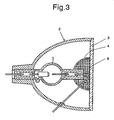
- Figs. 3 and 4 are a vertical sectional view and a cross (plan) sectional view, respectively, illustrating a discharge lamp according to a second example.
- This discharge lamp has substantially the same construction as the discharge lamp of the first embodiment, except that metal mesh sheets 6 are used instead of the punched metal plates 5 as the perforated plates.
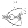
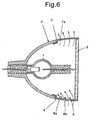
- Figs. 5 and 6 are a cross (plan) sectional view and a vertical sectional view, respectively, illustrating a discharge lamp according to an embodiment of the invention.
- the embodiment is substantially the same as the examples described above in that air is allowed to flow between the inside and outside of the reflector 2 through the holes 5a of the openings 4 formed in the reflector 2 to prevent the temperature rise around the lamp body 1.
- two slit plates 7, 8 formed with slits 7a, 8a are respectively fitted in the two openings 4 of the reflector 2.
- One slit plate 7 has simple slits 7a, while the other slit plate 8 has slits 8a and baffles 8b provided along the slits 8a.
- baffles 8b are provided as separate members.
- the slit plate 8 provided with the baffles 8b is located on a lower side of the discharge lamp for utilization of air convection by heat.
- an air blower such as a fan may be provided on a lateral side of the discharge lamp for blowing air toward the slits 8a so that the outside air can forcibly be supplied to the inside of the reflector 2.
- baffles 8b are provided on only one of the slit plates 8 in this embodiment, the baffles may be provided on both of the slit plates 7, 8.
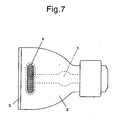
- a discharge lamp according to a third example has two large through-holes as openings 4 formed in non-contact with the front portion (particularly adjacent to the front portion of the reflector 2).
- the openings 4 may have any shape such as a circular, oval or rectangular shape.
- the openings 4 have perforated plates 5, the mesh sheets 6 or slit plates 7,8.
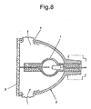
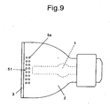
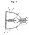
- a discharge lamp according to a fourth example is constructed such that vent portions each having a multiplicity of small diameter through-holes 5a are provided integrally with a reflector 2 thereof, particularly adjacent to the front portion of the reflector 2.
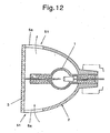
- Fig.11 and 12 are a front view and a cross sectional view, respectively, illustrating a modified fourth example.
- a discharge lamp according to a fourth example is constructed such that holes 5a shaped like the teeth of a comb are provided integrally with a reflector 2 thereof, particularly adjacent to the front portion of the reflector 2.
- the said through-holes 5a and holes 5a shaped like the teeth of a comb are formed at two points of the front portion of the reflector 2 or at the periphery of the front portion of the reflector 2.
- the holes 5a are in communication with the front portion of the reflector 2.
- This examples offer the same effects as the first to third examples and, in addition, are advantageous in that the number of parts can be reduced in comparison with the first to third examples.
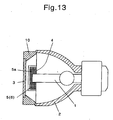
- Fig.13 , 14 and 15 are a vertical sectional view, a cross sectional view, and a inside view of a ring spacer used for this example, respectively, illustrating a discharge lamp according to an example.
- the discharge lamp comprises a lamp body 1, a reflector 2 having the lamp body 1 at the center of it, ring spacer 10 fitted on a front portion of the reflector 2, and a front glass fitted on the ring spacer 10.
- the ring spacer 10 has two rectangular openings 4 as the vent portions at the rear portion of it, wherein the front portion of the reflector 2 is fitted.
- the ring spacer 10 can adopt two rectangular openings 4 at the front portion of it, wherein the front glass 3 is fitted. (not-illustrated)
- the positions and configurations of the openings 4 are not limited to those illustrated, but the openings 4 may have any shape such as a circular, oval or rectangular shape and be formed in non-contact with the front portion.
- Punched metal plates, ceramic plates with perforation or heat-resistant plastics plates with perforations as perforated plates 5 are respectively fitted in the openings 4 of the ring spacer 10.
- the punched metal plates 5 are used as the perforated plates in this example, plates each formed with a multiplicity of drilled holes or slits, or expanded metal mesh plates each obtained by expanding an incised metal plate may be used as the perforated plates.
- a space defined by the reflector 2, ring spacer 10, and the front glass 3 around the lamp body 1 is not a hermetic space and, hence, heat generated when the lamp body is lit can be released to the outside through the holes 5a. Therefore, a higher-pressure and higher-wattage lamp body can be employed as the lamp body 1, making it possible to produce a discharge lamp, for example, having a wattage higher than 150W.
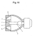
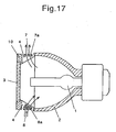
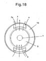
- Figs. 16 , 17 and 18 are a cross (plan) sectional view, a vertical sectional view respectively, illustrating a discharge lamp, and a inside view of a ring spacer according to a second embodiment of the invention.
- the second embodiment is substantially the same as the first embodiment described above in that air is allowed to flow between the inside and outside of the reflector 2 through the openings 4 formed in the ring spacer 10 to prevent the temperature rise around the lamp body 1.
- two slit plates 7, 8 formed with slits are respectively fitted in the two openings 4 of the reflector 2.
- One slit plate 7 has simple slits 7a, while the other slit plate 8 has slits 8a and baffles 8b provided along the slits 8a.
- baffles 8b are provided as separate members.
- the slit plate 8 provided with the baffles 8b is located on a lower side of the discharge lamp for utilization of air convection by heat.
- an air blower such as a fan may be provided on a lateral side of the discharge lamp for blowing air toward the slits 8a so that the outside air can forcibly be supplied to the inside of the reflector 2.
- baffles 8b are provided on only one of the slit plates 8 in this embodiment, the baffles may be provided on both of the slit plates 7, 8.
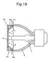
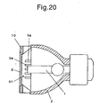
- a discharge lamp according to a sixth example are constructed such that vent portions each having a multiplicity of small diameter through-holes are provided integrally with a reflector thereof, or vent portions shaped like the teeth of a comb formed therein ( Fig.20 ) particularly adjacent to the front portion of the reflector 2( Fig.19 ).
- This example offers the same effects as the previous examples and, in addition, is advantageous in that the number of parts can be reduced in comparison with the said examples.
- the size, number, positions and configuration of the holes or the slits and the fineness of the meshes for the air ventilation may properly be determined on the basis of the size, wattage, pressure and material of the lamp body and the size and configuration of the reflector for effective heat release and for prevention of the scattering of the broken pieces of the lamp body.
- the present invention provides a discharge lamp which employs a higher-pressure and higher-wattage lamp body and is capable of effectively preventing the scattering of broken pieces of the lamp body at explosion of the lamp body.
Landscapes
- Arrangement Of Elements, Cooling, Sealing, Or The Like Of Lighting Devices (AREA)
- Projection Apparatus (AREA)
- Non-Portable Lighting Devices Or Systems Thereof (AREA)
- Vessels And Coating Films For Discharge Lamps (AREA)
- Light Sources And Details Of Projection-Printing Devices (AREA)
Claims (2)
- Entladungslampen-Baugruppe, die einen Reflektor (2), ein Frontglas (3) und einen Lampenkörper (1) darin umfaßt, wobei der Reflektor (2) einen Lüftungsabschnitt (4) mit einer Vielzahl von Durchgangslöchern (5a) hat, die in einem Seitenabschnitt des Reflektors (2) nahe einem vorderen Abschnitt desselben ausgebildet sind, wobei die Durchgangslöcher (5a) als Schlitze (7a, 8a) ausgebildet sind, die sich in einer Schlitzplatte (7, 8) befinden, und die Schlitzplatte (7, 8) in einen ausgeschnittenen Abschnitt des Reflektors (2) eingesetzt ist, dadurch gekennzeichnet, daß in der Schlitzplatte (8) entlang der Schlitze (8a) Leiteinrichtungen (8b) vorgesehen sind, zum Lenken von in einen Innenraum des Reflektors (2) eingeleiteter Außenluft durch die Schlitze (8a) in Richtung eines Hochtemperaturabschnitts des Lampenkörpers (1).
- Entladungslampen-Baugruppe, die einen Reflektor (2) umfaßt und einen Lampenkörper (1), einen Distanzring (10), der an einem vorderen Abschnitt des Reflektors (2) angefügt ist, und ein Frontglas (3) aufweist, das an einem vorderen Abschnitt des Distanzrings (10) angefügt ist, wobei der Distanzring (10) einen Lüftungsabschnitt (4) mit einer Vielzahl von darin ausgebildeten Durchgangslöchern (5a) hat, wobei die Durchgangslöcher (5a) als Schlitze (7a, 8a) ausgebildet sind, die sich in einer Schlitzplatte (7, 8) befinden, und die Schlitzplatte (7, 8) in einen ausgeschnittenen Abschnitt des Distanzrings (10) eingesetzt ist, dadurch gekennzeichnet, daß in der Schlitzplatte (8) entlang der Schlitze (8a) Leitbleche (8b) vorgesehen sind, zum Lenken von in einen Innenraum des Reflektors (2) eingeleiteter Außenluft durch die Schlitze (8a) in Richtung eines Hochtemperaturabschnitts des Lampenkörpers (1).
Applications Claiming Priority (4)
| Application Number | Priority Date | Filing Date | Title |
|---|---|---|---|
| JP31079398 | 1998-10-30 | ||
| JP31079398 | 1998-10-30 | ||
| JP20326799A JP2000200511A (ja) | 1998-10-30 | 1999-07-16 | 放電灯 |
| JP20326799 | 1999-07-16 |
Publications (3)
| Publication Number | Publication Date |
|---|---|
| EP1003202A2 EP1003202A2 (de) | 2000-05-24 |
| EP1003202A3 EP1003202A3 (de) | 2000-11-15 |
| EP1003202B1 true EP1003202B1 (de) | 2008-05-07 |
Family
ID=26513837
Family Applications (1)
| Application Number | Title | Priority Date | Filing Date |
|---|---|---|---|
| EP99308633A Expired - Lifetime EP1003202B1 (de) | 1998-10-30 | 1999-10-29 | Entladungslampe |
Country Status (4)
| Country | Link |
|---|---|
| US (1) | US6509674B1 (de) |
| EP (1) | EP1003202B1 (de) |
| JP (1) | JP2000200511A (de) |
| DE (1) | DE69938640D1 (de) |
Families Citing this family (41)
| Publication number | Priority date | Publication date | Assignee | Title |
|---|---|---|---|---|
| JP2001345069A (ja) | 2000-05-31 | 2001-12-14 | Matsushita Electric Ind Co Ltd | 放電ランプおよびランプユニット、ならびにランプユニットの製造方法 |
| DE10040887A1 (de) * | 2000-08-18 | 2001-08-30 | Philips Corp Intellectual Pty | Halogen-Glühlampe für Kraftfahrzeuge |
| JP3664065B2 (ja) | 2000-09-29 | 2005-06-22 | セイコーエプソン株式会社 | 光源装置およびプロジェクタ |
| JP3512745B2 (ja) * | 2001-01-18 | 2004-03-31 | 松下電器産業株式会社 | 光源装置及びこれを用いたプロジェクタ |
| US6759794B2 (en) * | 2001-04-27 | 2004-07-06 | General Electric Company | Discharge lamp with vented reflector |
| WO2002097529A1 (en) * | 2001-05-28 | 2002-12-05 | Seiko Epson Corporation | Projector |
| JP3987366B2 (ja) * | 2001-10-11 | 2007-10-10 | 三菱電機株式会社 | 光源装置及び投写型表示装置 |
| JP4096598B2 (ja) * | 2001-11-06 | 2008-06-04 | 株式会社日立製作所 | 投影装置用光源及びそれを用いた投写型画像ディスプレイ装置 |
| JP4055420B2 (ja) * | 2002-01-23 | 2008-03-05 | セイコーエプソン株式会社 | 光源装置およびこの光源装置を備えるプロジェクタ |
| US7052147B2 (en) * | 2003-02-20 | 2006-05-30 | Seiko Epson Corporation | Light source, and projector provided with the light source |
| JP3829813B2 (ja) * | 2003-02-25 | 2006-10-04 | セイコーエプソン株式会社 | プロジェクタ |
| US7230382B2 (en) * | 2003-04-21 | 2007-06-12 | Matsushita Electric Industrial Co., Ltd. | High pressure mercury lamp with vented reflector and image projection apparatus |
| JP4281436B2 (ja) | 2003-07-07 | 2009-06-17 | 株式会社日立製作所 | 映像表示装置 |
| JP4273912B2 (ja) * | 2003-10-07 | 2009-06-03 | ウシオ電機株式会社 | 光源装置 |
| JP4645101B2 (ja) * | 2004-01-23 | 2011-03-09 | 株式会社日立製作所 | プロジェクタ |
| JP4511275B2 (ja) * | 2004-01-30 | 2010-07-28 | 三洋電機株式会社 | 投写型映像表示装置 |
| JP2006011337A (ja) * | 2004-06-23 | 2006-01-12 | Plus Vision Corp | ランプ光源装置 |
| JP2006073432A (ja) * | 2004-09-03 | 2006-03-16 | Phoenix Denki Kk | 超高圧放電灯ユニットおよび光源装置 |
| JP2007335080A (ja) * | 2004-09-17 | 2007-12-27 | Light Boy Co Ltd | 照明装置 |
| DE102005000713A1 (de) * | 2005-01-03 | 2006-07-13 | Patent-Treuhand-Gesellschaft für elektrische Glühlampen mbH | Lampenmodul für Projektoren |
| JP2006260865A (ja) * | 2005-03-16 | 2006-09-28 | Mitsubishi Electric Corp | 光源装置及び投写型画像表示装置 |
| JP4656973B2 (ja) * | 2005-03-16 | 2011-03-23 | 三菱電機株式会社 | 光源装置及び投写型表示装置 |
| JP4502885B2 (ja) * | 2005-06-01 | 2010-07-14 | 三洋電機株式会社 | 投写型表示装置 |
| JP2007080796A (ja) * | 2005-09-16 | 2007-03-29 | Toshiba Corp | 光源ランプ |
| JP2007121824A (ja) * | 2005-10-31 | 2007-05-17 | Sanyo Electric Co Ltd | 投射型映像表示装置 |
| JP4166255B2 (ja) * | 2006-08-31 | 2008-10-15 | 三洋電機株式会社 | 光源装置及びそれを用いた投写型映像表示装置 |
| US9140968B2 (en) * | 2007-06-29 | 2015-09-22 | Seiko Epson Corporation | Projection device particle-containment shield |
| CN101413643B (zh) * | 2007-10-17 | 2010-06-16 | 鸿富锦精密工业(深圳)有限公司 | 发光装置 |
| TWI354181B (en) * | 2008-02-04 | 2011-12-11 | Coretronic Corp | Light source module of projector |
| DE102008021550B4 (de) * | 2008-04-28 | 2011-12-01 | Auer Lighting Gmbh | Hochleistungsleuchte mit einer Lampe und einem Reflektor |
| CN102047380A (zh) * | 2008-05-29 | 2011-05-04 | 奥斯兰姆有限公司 | 用于高压灯的防爆装置 |
| CN101644423B (zh) * | 2008-08-08 | 2011-03-30 | 鸿富锦精密工业(深圳)有限公司 | 光源保护装置 |
| CN102282412B (zh) | 2009-01-20 | 2014-05-14 | 松下电器产业株式会社 | 照明装置 |
| TW201102745A (en) * | 2009-07-15 | 2011-01-16 | Qisda Corp | Projector |
| JP4991834B2 (ja) * | 2009-12-17 | 2012-08-01 | シャープ株式会社 | 車両用前照灯 |
| JP5232815B2 (ja) * | 2010-02-10 | 2013-07-10 | シャープ株式会社 | 車両用前照灯 |
| US20110280033A1 (en) * | 2010-05-17 | 2011-11-17 | Sharp Kabushiki Kaisha | Light-emitting device, illumination device, and vehicle headlamp |
| US8733996B2 (en) | 2010-05-17 | 2014-05-27 | Sharp Kabushiki Kaisha | Light emitting device, illuminating device, and vehicle headlamp |
| GB2482910A (en) * | 2010-08-20 | 2012-02-22 | Gm Global Tech Operations Inc | Vehicle lamp |
| US9816677B2 (en) | 2010-10-29 | 2017-11-14 | Sharp Kabushiki Kaisha | Light emitting device, vehicle headlamp, illumination device, and laser element |
| CN104180173A (zh) * | 2014-06-15 | 2014-12-03 | 王玲玲 | 一种吸盘式照明装置 |
Family Cites Families (15)
| Publication number | Priority date | Publication date | Assignee | Title |
|---|---|---|---|---|
| US3684908A (en) * | 1970-09-25 | 1972-08-15 | Itt | Sealed beam high intensity xenon lamp with cooling structure |
| US4053759A (en) * | 1973-04-27 | 1977-10-11 | Optical Radiation Corporation | Lamphouse and module for photographic slide projectors |
| DE3033688A1 (de) * | 1980-09-08 | 1982-04-22 | Patent-Treuhand-Gesellschaft für elektrische Glühlampen mbH, 8000 München | Anordnung mit hochdruckentladungslampe und reflektor als baueinheit |
| US4925295A (en) * | 1986-03-17 | 1990-05-15 | Casio Computer Co., Ltd. | Projection display apparatus |
| US5220235A (en) * | 1990-04-20 | 1993-06-15 | Koito Manufacturing Co., Ltd. | Discharge lamp device |
| US5377086A (en) * | 1992-04-03 | 1994-12-27 | Sportlite, Inc. | Lighting apparatus |
| KR100326687B1 (ko) * | 1992-10-30 | 2002-06-20 | 요트.게.아. 롤페즈 | 전기램프및반사기장치 |
| WO1996027205A1 (en) * | 1995-03-02 | 1996-09-06 | Philips Electronics N.V. | Electric reflector lamp |
| DE19624860A1 (de) * | 1996-04-04 | 1997-10-09 | Peter Grimm | Elektronische Entladungslampe |
| JP3381566B2 (ja) * | 1997-07-18 | 2003-03-04 | ウシオ電機株式会社 | 光源ユニット |
| US6133676A (en) * | 1997-09-10 | 2000-10-17 | Chen; Chun Tsun | Double-enveloped halogen bulb provided with protuberances in the outer surface of the envelope |
| US5947590A (en) * | 1997-09-15 | 1999-09-07 | Hughes-Jvc Technology Corporation | High power arc lamp reflector with shroud and plurality of cooling fins on exterior surface of reflector for image projector |
| JPH11195322A (ja) * | 1997-11-04 | 1999-07-21 | Seiko Epson Corp | 光源装置および投写型表示装置 |
| US6078136A (en) * | 1998-11-06 | 2000-06-20 | Royal Lite Manufacturing And Supply Corp. | Fluorescent lamp with a protective assembly having vent holes |
| US6306010B1 (en) * | 1999-10-26 | 2001-10-23 | Industrial Gasket, Inc. | Method of forming a hole in a glass reflector |
-
1999
- 1999-07-16 JP JP20326799A patent/JP2000200511A/ja active Pending
- 1999-10-27 US US09/427,552 patent/US6509674B1/en not_active Expired - Lifetime
- 1999-10-29 DE DE69938640T patent/DE69938640D1/de not_active Expired - Lifetime
- 1999-10-29 EP EP99308633A patent/EP1003202B1/de not_active Expired - Lifetime
Also Published As
| Publication number | Publication date |
|---|---|
| JP2000200511A (ja) | 2000-07-18 |
| EP1003202A2 (de) | 2000-05-24 |
| US6509674B1 (en) | 2003-01-21 |
| DE69938640D1 (de) | 2008-06-19 |
| EP1003202A3 (de) | 2000-11-15 |
Similar Documents
| Publication | Publication Date | Title |
|---|---|---|
| US6509674B1 (en) | Discharge lamp with ventilation passage | |
| US6183114B1 (en) | Halogen torchiere light | |
| US5138541A (en) | Lamp with ventilated housing | |
| US6402346B1 (en) | Easy-heat-dissipation spotlight structure | |
| CA2391724C (en) | Heat distorting support clip for air handling luminaire | |
| US5091835A (en) | High intensity lamp with improved air flow ventilation | |
| US5743632A (en) | Thermally controlled light fixture | |
| CA2266345A1 (en) | Lamp cartridge | |
| EP1064494B1 (de) | Operationslampe mit verbesserter kühlung | |
| US5722753A (en) | Lamp device of liquid-crystal projection apparatus | |
| US20040085770A1 (en) | Luminaire | |
| US5651609A (en) | Convection venting lensed reflector-type compact fluorescent lamp system | |
| US5515251A (en) | Incorporated lighting system in furniture | |
| US8100559B2 (en) | Compact fluorescent lamp high bay luminaire | |
| CN216952796U (zh) | 一种照明装置 | |
| JPH08102213A (ja) | 照明器具 | |
| CN212204210U (zh) | 设有散热装置的追光灯 | |
| JP2007012368A (ja) | 車両用灯具 | |
| US6268701B1 (en) | Fluorescent light ballast convective cooling means | |
| KR200295613Y1 (ko) | 과열 방지수단이 강구된 조명등 | |
| JP4294388B2 (ja) | レフレクタ付き放電ランプ | |
| US5446636A (en) | Light fixture with improved heat dissipation characteristics | |
| JP2002334609A (ja) | 放電ランプアセンブリ | |
| GB2336426A (en) | Adjustable lamp | |
| US7618168B1 (en) | Shatter glass guard and venting effect design |
Legal Events
| Date | Code | Title | Description |
|---|---|---|---|
| PUAI | Public reference made under article 153(3) epc to a published international application that has entered the european phase |
Free format text: ORIGINAL CODE: 0009012 |
|
| AK | Designated contracting states |
Kind code of ref document: A2 Designated state(s): BE DE FR GB NL |
|
| AX | Request for extension of the european patent |
Free format text: AL;LT;LV;MK;RO;SI |
|
| 17P | Request for examination filed |
Effective date: 20000518 |
|
| PUAL | Search report despatched |
Free format text: ORIGINAL CODE: 0009013 |
|
| AK | Designated contracting states |
Kind code of ref document: A3 Designated state(s): AT BE CH CY DE DK ES FI FR GB GR IE IT LI LU MC NL PT SE |
|
| AX | Request for extension of the european patent |
Free format text: AL;LT;LV;MK;RO;SI |
|
| AKX | Designation fees paid |
Free format text: BE DE FR GB NL |
|
| 17Q | First examination report despatched |
Effective date: 20050923 |
|
| GRAP | Despatch of communication of intention to grant a patent |
Free format text: ORIGINAL CODE: EPIDOSNIGR1 |
|
| GRAS | Grant fee paid |
Free format text: ORIGINAL CODE: EPIDOSNIGR3 |
|
| GRAA | (expected) grant |
Free format text: ORIGINAL CODE: 0009210 |
|
| AK | Designated contracting states |
Kind code of ref document: B1 Designated state(s): BE DE FR GB NL |
|
| REG | Reference to a national code |
Ref country code: GB Ref legal event code: FG4D |
|
| REF | Corresponds to: |
Ref document number: 69938640 Country of ref document: DE Date of ref document: 20080619 Kind code of ref document: P |
|
| PG25 | Lapsed in a contracting state [announced via postgrant information from national office to epo] |
Ref country code: NL Free format text: LAPSE BECAUSE OF FAILURE TO SUBMIT A TRANSLATION OF THE DESCRIPTION OR TO PAY THE FEE WITHIN THE PRESCRIBED TIME-LIMIT Effective date: 20080507 |
|
| NLV1 | Nl: lapsed or annulled due to failure to fulfill the requirements of art. 29p and 29m of the patents act | ||
| PLBE | No opposition filed within time limit |
Free format text: ORIGINAL CODE: 0009261 |
|
| STAA | Information on the status of an ep patent application or granted ep patent |
Free format text: STATUS: NO OPPOSITION FILED WITHIN TIME LIMIT |
|
| 26N | No opposition filed |
Effective date: 20090210 |
|
| REG | Reference to a national code |
Ref country code: FR Ref legal event code: ST Effective date: 20090630 |
|
| PG25 | Lapsed in a contracting state [announced via postgrant information from national office to epo] |
Ref country code: FR Free format text: LAPSE BECAUSE OF NON-PAYMENT OF DUE FEES Effective date: 20081031 |
|
| PGFP | Annual fee paid to national office [announced via postgrant information from national office to epo] |
Ref country code: DE Payment date: 20101027 Year of fee payment: 12 |
|
| PGFP | Annual fee paid to national office [announced via postgrant information from national office to epo] |
Ref country code: GB Payment date: 20101027 Year of fee payment: 12 |
|
| PGFP | Annual fee paid to national office [announced via postgrant information from national office to epo] |
Ref country code: BE Payment date: 20111012 Year of fee payment: 13 |
|
| BERE | Be: lapsed |
Owner name: PHOENIX ELECTRIC CO., LTD. Effective date: 20121031 |
|
| GBPC | Gb: european patent ceased through non-payment of renewal fee |
Effective date: 20121029 |
|
| PG25 | Lapsed in a contracting state [announced via postgrant information from national office to epo] |
Ref country code: BE Free format text: LAPSE BECAUSE OF NON-PAYMENT OF DUE FEES Effective date: 20121031 Ref country code: GB Free format text: LAPSE BECAUSE OF NON-PAYMENT OF DUE FEES Effective date: 20121029 Ref country code: DE Free format text: LAPSE BECAUSE OF NON-PAYMENT OF DUE FEES Effective date: 20130501 |
|
| REG | Reference to a national code |
Ref country code: DE Ref legal event code: R119 Ref document number: 69938640 Country of ref document: DE Effective date: 20130501 |