EP1003204A2 - Lampe à caracteristiques controlables - Google Patents
Lampe à caracteristiques controlables Download PDFInfo
- Publication number
- EP1003204A2 EP1003204A2 EP99120957A EP99120957A EP1003204A2 EP 1003204 A2 EP1003204 A2 EP 1003204A2 EP 99120957 A EP99120957 A EP 99120957A EP 99120957 A EP99120957 A EP 99120957A EP 1003204 A2 EP1003204 A2 EP 1003204A2
- Authority
- EP
- European Patent Office
- Prior art keywords
- lamp
- fill
- bulb
- sulfur
- spectrum
- Prior art date
- Legal status (The legal status is an assumption and is not a legal conclusion. Google has not performed a legal analysis and makes no representation as to the accuracy of the status listed.)
- Withdrawn
Links
- 239000000126 substance Substances 0.000 claims abstract description 53
- NINIDFKCEFEMDL-UHFFFAOYSA-N Sulfur Chemical compound [S] NINIDFKCEFEMDL-UHFFFAOYSA-N 0.000 claims abstract description 45
- 239000011593 sulfur Substances 0.000 claims abstract description 43
- 229910052717 sulfur Inorganic materials 0.000 claims abstract description 43
- 230000003595 spectral effect Effects 0.000 claims abstract description 42
- 239000011669 selenium Substances 0.000 claims abstract description 39
- BUGBHKTXTAQXES-UHFFFAOYSA-N Selenium Chemical compound [Se] BUGBHKTXTAQXES-UHFFFAOYSA-N 0.000 claims abstract description 36
- 229910052711 selenium Inorganic materials 0.000 claims abstract description 36
- 238000001228 spectrum Methods 0.000 claims description 53
- 238000009826 distribution Methods 0.000 claims description 18
- 230000005855 radiation Effects 0.000 claims description 11
- 230000008878 coupling Effects 0.000 claims description 8
- 238000010168 coupling process Methods 0.000 claims description 8
- 238000005859 coupling reaction Methods 0.000 claims description 8
- 230000005284 excitation Effects 0.000 claims description 4
- 229910052783 alkali metal Inorganic materials 0.000 abstract description 8
- 150000001340 alkali metals Chemical class 0.000 abstract description 8
- 230000001976 improved effect Effects 0.000 abstract description 8
- 229910052751 metal Inorganic materials 0.000 abstract description 8
- 239000002184 metal Substances 0.000 abstract description 8
- 229910052784 alkaline earth metal Inorganic materials 0.000 abstract description 3
- 150000001342 alkaline earth metals Chemical class 0.000 abstract description 3
- 238000001816 cooling Methods 0.000 description 14
- 239000000654 additive Substances 0.000 description 13
- XKRFYHLGVUSROY-UHFFFAOYSA-N Argon Chemical compound [Ar] XKRFYHLGVUSROY-UHFFFAOYSA-N 0.000 description 12
- 239000000463 material Substances 0.000 description 10
- 230000001276 controlling effect Effects 0.000 description 9
- 150000001875 compounds Chemical class 0.000 description 8
- 230000000694 effects Effects 0.000 description 7
- 229910052786 argon Inorganic materials 0.000 description 6
- 230000002596 correlated effect Effects 0.000 description 6
- 239000011734 sodium Substances 0.000 description 6
- 230000008901 benefit Effects 0.000 description 5
- 230000008859 change Effects 0.000 description 5
- 238000010586 diagram Methods 0.000 description 5
- DGAQECJNVWCQMB-PUAWFVPOSA-M Ilexoside XXIX Chemical compound C[C@@H]1CC[C@@]2(CC[C@@]3(C(=CC[C@H]4[C@]3(CC[C@@H]5[C@@]4(CC[C@@H](C5(C)C)OS(=O)(=O)[O-])C)C)[C@@H]2[C@]1(C)O)C)C(=O)O[C@H]6[C@@H]([C@H]([C@@H]([C@H](O6)CO)O)O)O.[Na+] DGAQECJNVWCQMB-PUAWFVPOSA-M 0.000 description 4
- -1 InI Chemical class 0.000 description 4
- 239000004020 conductor Substances 0.000 description 4
- 239000000470 constituent Substances 0.000 description 4
- 239000012809 cooling fluid Substances 0.000 description 4
- 150000004820 halides Chemical class 0.000 description 4
- 230000001965 increasing effect Effects 0.000 description 4
- QSHDDOUJBYECFT-UHFFFAOYSA-N mercury Chemical compound [Hg] QSHDDOUJBYECFT-UHFFFAOYSA-N 0.000 description 4
- 229910052753 mercury Inorganic materials 0.000 description 4
- 229910052761 rare earth metal Inorganic materials 0.000 description 4
- 238000000926 separation method Methods 0.000 description 4
- VYPSYNLAJGMNEJ-UHFFFAOYSA-N silicon dioxide Inorganic materials O=[Si]=O VYPSYNLAJGMNEJ-UHFFFAOYSA-N 0.000 description 4
- 229910052708 sodium Inorganic materials 0.000 description 4
- 239000007787 solid Substances 0.000 description 4
- 238000009833 condensation Methods 0.000 description 3
- 230000005494 condensation Effects 0.000 description 3
- 239000007789 gas Substances 0.000 description 3
- 235000012239 silicon dioxide Nutrition 0.000 description 3
- 150000004763 sulfides Chemical class 0.000 description 3
- 238000013459 approach Methods 0.000 description 2
- 238000001675 atomic spectrum Methods 0.000 description 2
- 230000003190 augmentative effect Effects 0.000 description 2
- 230000006698 induction Effects 0.000 description 2
- 239000011261 inert gas Substances 0.000 description 2
- 229910001507 metal halide Inorganic materials 0.000 description 2
- 150000005309 metal halides Chemical class 0.000 description 2
- 150000002739 metals Chemical class 0.000 description 2
- 239000000203 mixture Substances 0.000 description 2
- 230000008635 plant growth Effects 0.000 description 2
- 239000010453 quartz Substances 0.000 description 2
- 230000000153 supplemental effect Effects 0.000 description 2
- 230000008093 supporting effect Effects 0.000 description 2
- 229910052716 thallium Inorganic materials 0.000 description 2
- BKVIYDNLLOSFOA-UHFFFAOYSA-N thallium Chemical compound [Tl] BKVIYDNLLOSFOA-UHFFFAOYSA-N 0.000 description 2
- OYPRJOBELJOOCE-UHFFFAOYSA-N Calcium Chemical compound [Ca] OYPRJOBELJOOCE-UHFFFAOYSA-N 0.000 description 1
- GYHNNYVSQQEPJS-UHFFFAOYSA-N Gallium Chemical compound [Ga] GYHNNYVSQQEPJS-UHFFFAOYSA-N 0.000 description 1
- WHXSMMKQMYFTQS-UHFFFAOYSA-N Lithium Chemical compound [Li] WHXSMMKQMYFTQS-UHFFFAOYSA-N 0.000 description 1
- 229910052765 Lutetium Inorganic materials 0.000 description 1
- FYYHWMGAXLPEAU-UHFFFAOYSA-N Magnesium Chemical compound [Mg] FYYHWMGAXLPEAU-UHFFFAOYSA-N 0.000 description 1
- ZLMJMSJWJFRBEC-UHFFFAOYSA-N Potassium Chemical compound [K] ZLMJMSJWJFRBEC-UHFFFAOYSA-N 0.000 description 1
- 229910018219 SeTe Inorganic materials 0.000 description 1
- 229910052770 Uranium Inorganic materials 0.000 description 1
- 230000000996 additive effect Effects 0.000 description 1
- 230000032683 aging Effects 0.000 description 1
- 239000003513 alkali Substances 0.000 description 1
- 229910052782 aluminium Inorganic materials 0.000 description 1
- XAGFODPZIPBFFR-UHFFFAOYSA-N aluminium Chemical compound [Al] XAGFODPZIPBFFR-UHFFFAOYSA-N 0.000 description 1
- 238000004458 analytical method Methods 0.000 description 1
- 230000002238 attenuated effect Effects 0.000 description 1
- 229910052788 barium Inorganic materials 0.000 description 1
- DSAJWYNOEDNPEQ-UHFFFAOYSA-N barium atom Chemical compound [Ba] DSAJWYNOEDNPEQ-UHFFFAOYSA-N 0.000 description 1
- 229910001638 barium iodide Inorganic materials 0.000 description 1
- 230000004888 barrier function Effects 0.000 description 1
- 239000002585 base Substances 0.000 description 1
- 229910052790 beryllium Inorganic materials 0.000 description 1
- ATBAMAFKBVZNFJ-UHFFFAOYSA-N beryllium atom Chemical compound [Be] ATBAMAFKBVZNFJ-UHFFFAOYSA-N 0.000 description 1
- 229910052792 caesium Inorganic materials 0.000 description 1
- TVFDJXOCXUVLDH-UHFFFAOYSA-N caesium atom Chemical compound [Cs] TVFDJXOCXUVLDH-UHFFFAOYSA-N 0.000 description 1
- 229910052791 calcium Inorganic materials 0.000 description 1
- 239000011575 calcium Substances 0.000 description 1
- 229910001622 calcium bromide Inorganic materials 0.000 description 1
- WGEFECGEFUFIQW-UHFFFAOYSA-L calcium dibromide Chemical compound [Ca+2].[Br-].[Br-] WGEFECGEFUFIQW-UHFFFAOYSA-L 0.000 description 1
- 238000006243 chemical reaction Methods 0.000 description 1
- 239000011248 coating agent Substances 0.000 description 1
- 238000000576 coating method Methods 0.000 description 1
- 238000013329 compounding Methods 0.000 description 1
- 230000000875 corresponding effect Effects 0.000 description 1
- 230000007423 decrease Effects 0.000 description 1
- 230000003247 decreasing effect Effects 0.000 description 1
- 230000006866 deterioration Effects 0.000 description 1
- VDQVEACBQKUUSU-UHFFFAOYSA-M disodium;sulfanide Chemical compound [Na+].[Na+].[SH-] VDQVEACBQKUUSU-UHFFFAOYSA-M 0.000 description 1
- 238000006073 displacement reaction Methods 0.000 description 1
- PXJJSXABGXMUSU-UHFFFAOYSA-N disulfur dichloride Chemical compound ClSSCl PXJJSXABGXMUSU-UHFFFAOYSA-N 0.000 description 1
- 238000010891 electric arc Methods 0.000 description 1
- 229910052733 gallium Inorganic materials 0.000 description 1
- 238000010438 heat treatment Methods 0.000 description 1
- 238000005286 illumination Methods 0.000 description 1
- 230000006872 improvement Effects 0.000 description 1
- 229910052738 indium Inorganic materials 0.000 description 1
- APFVFJFRJDLVQX-UHFFFAOYSA-N indium atom Chemical compound [In] APFVFJFRJDLVQX-UHFFFAOYSA-N 0.000 description 1
- 230000001939 inductive effect Effects 0.000 description 1
- 229910052746 lanthanum Inorganic materials 0.000 description 1
- FZLIPJUXYLNCLC-UHFFFAOYSA-N lanthanum atom Chemical compound [La] FZLIPJUXYLNCLC-UHFFFAOYSA-N 0.000 description 1
- 239000007788 liquid Substances 0.000 description 1
- 239000004973 liquid crystal related substance Substances 0.000 description 1
- 229910052744 lithium Inorganic materials 0.000 description 1
- OHSVLFRHMCKCQY-UHFFFAOYSA-N lutetium atom Chemical compound [Lu] OHSVLFRHMCKCQY-UHFFFAOYSA-N 0.000 description 1
- 229910052749 magnesium Inorganic materials 0.000 description 1
- 239000011777 magnesium Substances 0.000 description 1
- 238000004519 manufacturing process Methods 0.000 description 1
- 238000005259 measurement Methods 0.000 description 1
- 238000000034 method Methods 0.000 description 1
- 230000003287 optical effect Effects 0.000 description 1
- 229910052958 orpiment Inorganic materials 0.000 description 1
- RVTZCBVAJQQJTK-UHFFFAOYSA-N oxygen(2-);zirconium(4+) Chemical compound [O-2].[O-2].[Zr+4] RVTZCBVAJQQJTK-UHFFFAOYSA-N 0.000 description 1
- 229910052700 potassium Inorganic materials 0.000 description 1
- 239000011591 potassium Substances 0.000 description 1
- 229910052705 radium Inorganic materials 0.000 description 1
- HCWPIIXVSYCSAN-UHFFFAOYSA-N radium atom Chemical compound [Ra] HCWPIIXVSYCSAN-UHFFFAOYSA-N 0.000 description 1
- 229910052701 rubidium Inorganic materials 0.000 description 1
- IGLNJRXAVVLDKE-UHFFFAOYSA-N rubidium atom Chemical compound [Rb] IGLNJRXAVVLDKE-UHFFFAOYSA-N 0.000 description 1
- 229910052706 scandium Inorganic materials 0.000 description 1
- SIXSYDAISGFNSX-UHFFFAOYSA-N scandium atom Chemical compound [Sc] SIXSYDAISGFNSX-UHFFFAOYSA-N 0.000 description 1
- LNBXMNQCXXEHFT-UHFFFAOYSA-N selenium tetrachloride Chemical compound Cl[Se](Cl)(Cl)Cl LNBXMNQCXXEHFT-UHFFFAOYSA-N 0.000 description 1
- FESBVLZDDCQLFY-UHFFFAOYSA-N sete Chemical compound [Te]=[Se] FESBVLZDDCQLFY-UHFFFAOYSA-N 0.000 description 1
- 239000000377 silicon dioxide Substances 0.000 description 1
- 229910052979 sodium sulfide Inorganic materials 0.000 description 1
- 229910052712 strontium Inorganic materials 0.000 description 1
- CIOAGBVUUVVLOB-UHFFFAOYSA-N strontium atom Chemical compound [Sr] CIOAGBVUUVVLOB-UHFFFAOYSA-N 0.000 description 1
- KRIJWFBRWPCESA-UHFFFAOYSA-L strontium iodide Chemical compound [Sr+2].[I-].[I-] KRIJWFBRWPCESA-UHFFFAOYSA-L 0.000 description 1
- 229910001643 strontium iodide Inorganic materials 0.000 description 1
- 150000003464 sulfur compounds Chemical class 0.000 description 1
- 238000001429 visible spectrum Methods 0.000 description 1
- 229910052724 xenon Inorganic materials 0.000 description 1
- FHNFHKCVQCLJFQ-UHFFFAOYSA-N xenon atom Chemical compound [Xe] FHNFHKCVQCLJFQ-UHFFFAOYSA-N 0.000 description 1
- 229910052727 yttrium Inorganic materials 0.000 description 1
- VWQVUPCCIRVNHF-UHFFFAOYSA-N yttrium atom Chemical compound [Y] VWQVUPCCIRVNHF-UHFFFAOYSA-N 0.000 description 1
- 229910001928 zirconium oxide Inorganic materials 0.000 description 1
Images


Classifications
-
- G—PHYSICS
- G03—PHOTOGRAPHY; CINEMATOGRAPHY; ANALOGOUS TECHNIQUES USING WAVES OTHER THAN OPTICAL WAVES; ELECTROGRAPHY; HOLOGRAPHY
- G03F—PHOTOMECHANICAL PRODUCTION OF TEXTURED OR PATTERNED SURFACES, e.g. FOR PRINTING, FOR PROCESSING OF SEMICONDUCTOR DEVICES; MATERIALS THEREFOR; ORIGINALS THEREFOR; APPARATUS SPECIALLY ADAPTED THEREFOR
- G03F7/00—Photomechanical, e.g. photolithographic, production of textured or patterned surfaces, e.g. printing surfaces; Materials therefor, e.g. comprising photoresists; Apparatus specially adapted therefor
- G03F7/70—Microphotolithographic exposure; Apparatus therefor
- G03F7/70008—Production of exposure light, i.e. light sources
- G03F7/70016—Production of exposure light, i.e. light sources by discharge lamps
-
- H—ELECTRICITY
- H01—ELECTRIC ELEMENTS
- H01J—ELECTRIC DISCHARGE TUBES OR DISCHARGE LAMPS
- H01J61/00—Gas-discharge or vapour-discharge lamps
- H01J61/02—Details
- H01J61/025—Associated optical elements
-
- H—ELECTRICITY
- H01—ELECTRIC ELEMENTS
- H01J—ELECTRIC DISCHARGE TUBES OR DISCHARGE LAMPS
- H01J61/00—Gas-discharge or vapour-discharge lamps
- H01J61/02—Details
- H01J61/04—Electrodes; Screens; Shields
-
- H—ELECTRICITY
- H01—ELECTRIC ELEMENTS
- H01J—ELECTRIC DISCHARGE TUBES OR DISCHARGE LAMPS
- H01J61/00—Gas-discharge or vapour-discharge lamps
- H01J61/02—Details
- H01J61/12—Selection of substances for gas fillings; Specified operating pressure or temperature
-
- H—ELECTRICITY
- H01—ELECTRIC ELEMENTS
- H01J—ELECTRIC DISCHARGE TUBES OR DISCHARGE LAMPS
- H01J61/00—Gas-discharge or vapour-discharge lamps
- H01J61/02—Details
- H01J61/24—Means for obtaining or maintaining the desired pressure within the vessel
-
- H—ELECTRICITY
- H01—ELECTRIC ELEMENTS
- H01J—ELECTRIC DISCHARGE TUBES OR DISCHARGE LAMPS
- H01J61/00—Gas-discharge or vapour-discharge lamps
- H01J61/02—Details
- H01J61/38—Devices for influencing the colour or wavelength of the light
-
- H—ELECTRICITY
- H01—ELECTRIC ELEMENTS
- H01J—ELECTRIC DISCHARGE TUBES OR DISCHARGE LAMPS
- H01J61/00—Gas-discharge or vapour-discharge lamps
- H01J61/02—Details
- H01J61/52—Cooling arrangements; Heating arrangements; Means for circulating gas or vapour within the discharge space
-
- H—ELECTRICITY
- H01—ELECTRIC ELEMENTS
- H01J—ELECTRIC DISCHARGE TUBES OR DISCHARGE LAMPS
- H01J61/00—Gas-discharge or vapour-discharge lamps
- H01J61/02—Details
- H01J61/54—Igniting arrangements, e.g. promoting ionisation for starting
-
- H—ELECTRICITY
- H01—ELECTRIC ELEMENTS
- H01J—ELECTRIC DISCHARGE TUBES OR DISCHARGE LAMPS
- H01J61/00—Gas-discharge or vapour-discharge lamps
- H01J61/82—Lamps with high-pressure unconstricted discharge having a cold pressure > 400 Torr
-
- H—ELECTRICITY
- H01—ELECTRIC ELEMENTS
- H01J—ELECTRIC DISCHARGE TUBES OR DISCHARGE LAMPS
- H01J65/00—Lamps without any electrode inside the vessel; Lamps with at least one main electrode outside the vessel
- H01J65/04—Lamps in which a gas filling is excited to luminesce by an external electromagnetic field or by external corpuscular radiation, e.g. for indicating plasma display panels
- H01J65/042—Lamps in which a gas filling is excited to luminesce by an external electromagnetic field or by external corpuscular radiation, e.g. for indicating plasma display panels by an external electromagnetic field
- H01J65/044—Lamps in which a gas filling is excited to luminesce by an external electromagnetic field or by external corpuscular radiation, e.g. for indicating plasma display panels by an external electromagnetic field the field being produced by a separate microwave unit
-
- H—ELECTRICITY
- H01—ELECTRIC ELEMENTS
- H01J—ELECTRIC DISCHARGE TUBES OR DISCHARGE LAMPS
- H01J65/00—Lamps without any electrode inside the vessel; Lamps with at least one main electrode outside the vessel
- H01J65/04—Lamps in which a gas filling is excited to luminesce by an external electromagnetic field or by external corpuscular radiation, e.g. for indicating plasma display panels
- H01J65/042—Lamps in which a gas filling is excited to luminesce by an external electromagnetic field or by external corpuscular radiation, e.g. for indicating plasma display panels by an external electromagnetic field
- H01J65/046—Lamps in which a gas filling is excited to luminesce by an external electromagnetic field or by external corpuscular radiation, e.g. for indicating plasma display panels by an external electromagnetic field the field being produced by using capacitive means around the vessel
-
- H—ELECTRICITY
- H01—ELECTRIC ELEMENTS
- H01J—ELECTRIC DISCHARGE TUBES OR DISCHARGE LAMPS
- H01J65/00—Lamps without any electrode inside the vessel; Lamps with at least one main electrode outside the vessel
- H01J65/04—Lamps in which a gas filling is excited to luminesce by an external electromagnetic field or by external corpuscular radiation, e.g. for indicating plasma display panels
- H01J65/042—Lamps in which a gas filling is excited to luminesce by an external electromagnetic field or by external corpuscular radiation, e.g. for indicating plasma display panels by an external electromagnetic field
- H01J65/048—Lamps in which a gas filling is excited to luminesce by an external electromagnetic field or by external corpuscular radiation, e.g. for indicating plasma display panels by an external electromagnetic field the field being produced by using an excitation coil
Definitions
- One aspect of the present invention relates to an improved visible lamp, and particularly to such a lamp which has a controllable spectral output.
- the color of the light which is provided by a lamp is determined by the spectral energy distribution of the emitted radiation.
- visible light sources emit over the spectral range of 350-750 nanometers.
- discharge lamps are typically provided with different spectral emphases by employing fill additives.
- a metal halide lamp which is doped with thallium emphasizes the green part of the spectrum, whereas one which is doped with sodium would emphasize the yellow.
- One disadvantage of such lamps is that a different additive or combination of additives must be used to make each differently tinted lamp, additives must be used to make each differently tinted lamp, thus introducing manufacturing complexities.
- the spectra of lamps using additives are prone to change over time.
- U.S. Patent No. 4,978,891 German DE A 4 011 951 discloses using controllable cooling means to control the condensation of a constituent of a lamp having a multi-constituent fill.
- Japanese Publication No. JP 6227244 B and U.S. Patent No. 4,974,227 discloses controlling the pressure of a mercury lamp by temperature control
- U.S. Patent No. 4,476,413 discloses an atomic spectral lamp in which the amount of elemental vapor is controlled by heating means
- U.S. Patent No. 4,945,290 discloses a dielectric barrier discharge device in which the electron energy distribution can be optimized by controlling the pressure.
- a new type of discharge lamp which uses a fill which contains a sulfur or selenium containing substance.
- the fill is present at a pressure of at least about 1 bar (1 atmosphere), and is excited at a relatively high power density.
- the lamp produces a molecular spectrum in the visible part of the spectrum at a relatively high efficacy and has exhibited a long lifetime and a stable color output over time.
- the tint of the lamp may be varied so as to have a spectral peak at a predetermined wavelength within a range of continuous wavelengths by varying the fill amount within a continuous rang of fill amounts which correlate with peak wavelengths in the continuous wavelength range.
- the spectral output or color temperature may vary around the periphery of the bulb. It is of course desirable for many applications, for the spectral output to be uniform around the bulb surface, so that all portions of the illuminating energy appear to be the same color.
- a discharge lamp which has a fill substance which emits primarily throughout the visible part of the spectrum, and which has the property of having a visible spectral distribution which can be changed by controlling the density of the fill substance.
- a discharge lamp which has a fill substance which emits primarily throughout the visible part of the spectrum, and which has the property of having a visible spectral characteristic which can be shifted in wavelength without substantially changing the shape of the characteristic by controlling the density of the fill substance.
- discharge lamps which have a sulfur or selenium based fill are provided with different spectral emphases or tints by controlling the fill density of a sulfur or selenium containing fill substance.
- discharge lamps having visible spectral characteristics of substantially the same shape, but shifted in wavelength from each other, are provided by controlling the fill density of a sulfur or selenium containing fill substance.
- the spectral output of a discharge lamp having a sulfur or selenium containing fill is controlled in real time by controlling the fill density during operation. This may be accomplished by controlling the cooling which is applied to the lamp bulb to condense more or less of the fill substance out of the gaseous fill.
- the bulb fill is constituted so as to obviate the above-described effects of spatially varying spectral output or color temperature.
- the lamp my be configured so that it emits with a uniform color temperature around the bulb surface. Additionally, operation at lower power levels without extinguishing may be possible.
- a substance is added to the bulb fill which improves the spatial uniformity of the color temperature of the light which is emitted by the bulb.
- a substance is added to the fill which improves the starting of the lamp.
- a substance is added to the fill which allows the lamp to be effectively operated at lower power levels.
- a substance is added to the fill which has a low ionization potential.
- a substance is added to the fill which is an alkali metal containing substance.
- a substance is added to the fill which is a III B metal containing substance.
- a substance is added to the fill which is an alkaline earth metal or a rare earth element containing substance.
- mercury is added to the fill.
- an improved bulb is provided, which may be used in a discharge lamp.
- FIG. 1 shows a microwave powered electrodeless lamp into which the present invention may be incorporated.
- a pair of magnetrons 1, 1' generate microwave energy which propagates along waveguides 2, 2'.
- the waveguides lead to microwave cavity 5 which is comprised of solid conductive wall, cup-shaped part 4, and metal mesh cup-shaped part 6, which are joined at their respective ends 4A, 6A.
- antenna slots 3, 3' which serve to couple microwave energy from the waveguide into the cavity where it causes an oscillating field to occur.
- a discharge bulb 7 including a supporting stem 7A is located within cavity 5.
- the supporting stem is connected through a hole (not shown) in solid cup-shaped part 4, to the shaft of a motor 8.
- the motor rotates the bulb 7 to improve the cooling of the bulb.
- the fill in bulb includes a sulfur or selenium containing substance. It is further desirable to use an inert gas, such as argon or xenon, which aids in starting the discharge.
- the lamp of Figure 1 may be characterized as a high pressure lamp.
- the fill in bulb 7 is present in amounts such that the fill pressure is at least 1 atmosphere or above when excited to operating temperature, and is preferably 2 to 20 bar (2 to 20 atmospheres).
- the fill pressure is mainly controlled by the primary radiating component, which typically has a substantially higher partial pressure than that of other constituents when the lamp is operational.
- the illumination provided by the lamp may be augmented in various regions of the spectrum by including certain additives in the fill.
- compounds of these elements may be used.
- InS, As 2 S 3 , S 2 Cl 2 , CS 2 , In 2 S 3 , SeS, SeOs, SeCl 4 , SeTe, P 2 Se 5 and Se 3 As 2 may be used.
- the compounds which are used have a low vapor pressure at room temperature, i.e., they are in a solid or liquid state, and a high vapor pressure at operating temperature.
- a sulfur containing substance includes both elemental sulfur and sulfur compounds, while the same is true for the corresponding terms as applied to selenium. It should be appreciated that the primary radiating component of the fill may be comprised of a combination of a sulfur containing substance and a selenium containing substance, rather than only one of these substances. Additionally, the primary radiating component may be comprised of a mixture of the elemental form and a compound(s) of a particular substance or substances.
- the fill is excited at power densities in excess of 50 watts/cc and preferably in excess of 100 watts/cc.
- the spectral energy distribution of a lamp as shown in Figure 1 is shown.
- the spectral energy distribution covers the range from 350 to 750 nanometers, which is generally the visible range.
- the spectrum has its peak at about 515 nanometers, and the output appears to be white with a green tint. As is seen, the spectrum is continuous throughout the visible range.
- Analyses of the spectral energy distribution according to the 1931 CIE determines a correlated color temperature of 6000 degrees Kelvin and x and y coordinates of .320 and .386 respectively on the chromaticity diagram.
- the bulb which provided the spectrum which is shown in Figure 2 was provided with a discharge fill consisting of 2.5 milligrams per cubic centimeter of sulfur, and .08 bar of argon (60 torr).
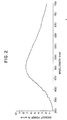
- FIG. 3 the spectral energy distribution of a second lamp made and operated according to the invention is shown.
- This lamp was operated under the same conditions as the lamp represented in Figure 2, but the lamp represented in Figure 3 was provided with sulfur of somewhat lesser density than the lamp represented in Figure 2, that is 1.3 milligrams per cubic centimeter.
- This bulb also had .08 bar (60 torr) of argon.
- the output appears white but in this case with a blue tint, and the peak of the spectral energy distribution occurs at about 490 nanometers.
- the correlated color temperature is 8500 degrees kelvin, while the x and y coordinates on the chromaticity diagram are .275 and .334 respectively.
- both of the spectra shown in Figures 2 and 3 ascend from near zero smoothly from the 350 nanometer mark to their respective peaks, and descend more gradually to a low level at the 750 nanometer mark. Aside from the slight jitter, the curves are smooth. This is in contrast to the ubiquitous variants of metal halide lamps which exhibit strong line spectra. Additionally, it is significant to note that the shape of the spectrum is substantially preserved between the first and the second spectra. However, due to the spectral shift, it will be seen that the amplitude of the spectrum shown in Figure 2, which peaks at 490 nanometers is higher at the lower wavelengths and lower at the higher wavelengths than that shown in Figure 3, which peaks at 515 nanometers.
- a sulfur containing substance as selenium containing substance or combinations thereof, the following is to be noted.
- sulfur will provide a higher color temperature and selenium a lower color temperature.
- a fill in which a combination of sulfur and selenium is used has the advantage that higher total vapor pressures can be obtained from the two somewhat independent partial pressures, and a further shift to the red can be obtained.
- a fill comprising a mixture of sulfur and selenium provides a spectrum having a shape as shown in Figures 2 or 3.
- the relative shift of the spectrum attained with a bulb using both materials in the fill can be controlled between the extremes of fills containing the only one of the materials by selecting the ratio of sulfur and selenium in the fill Increasing the sulfur density and decreasing the selenium density will raise the color temperature, and vice versa.
- Such lamps may have particular applicability to a red/green/blue (RGB) color display system.
- the region of the chromaticity diagram extending from about .200 to about .490 on the x axis, and about .200 to about .450 on the y axis is white light, while various subregions will have a discernable tint.
- a source which falls within the white region is suitable for use in an RGB color system in which the light from the source is separated into the three primary color beams which are modulated imagewise and recombined to form a color image. It is, however, desirable to be able to shift the spectrum while preserving its shape in order to provide an optimum spectrum for a particular RGB system.
- the spectral energy distribution of a particular lamp can be controlled during lamp operation.
- the effective fill density is changed by increasing the cooling of the bulb, such as by increasing the pressure of the cooling air which is delivered to cooling jets 9A, 9B, 9C, 9D in Figure 1 to the point that some of the fill in the bulb condenses on the inside of the envelope and ceases to participate in the discharge.
- a bulb may be modified to provide a special area or a side pipe may be provided in which the fill material will be selectively caused to condense. In this way the condensed fill will not interfere with the light emission from the bulb.
- the special area may simply be a certain area of an unmodified standard shaped bulb which is provided with augmented cooling.
- the cooling jet 9A which cools the lowest part of the bulb, whereat the stem is connected, may be operated at higher air pressure. In this way, fill condensation will occur at that area of the bulb which is out of the way of the emission directed at towards the lamps optics.
- the optics may comprise a reflector with its optical axis coincident with the cylindrical axis of the cavity.
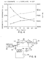
- filter 30 is provided and is located so as to receive light from the lamp.
- Filter 30, for example, may be a band pass filter which transmits light only in the blue region of the spectrum, and is followed by photodetector 32 which generates a comparison signal.
- Function generator 34 is also provided, which is capable of generating a preselected function signal of desired, arbitrary shape.
- the outputs of photodetector 32 and function generator 34 are fed to comparator 36, which generates a difference signal. This difference signal is fed back to the cooling fluid supply system to control the amount of cooling fluid impinging on the bulb.
- an exemplary control for the cooling fluid supply is a needle valve 40, the position of which is controlled by stepping motor 42.
- the input to pressurized air supply 20 could be throttled or the supply could be vented, to control cooling.
- a difference signal results, which causes the cooling of the lamp bulb 8 to vary, until the difference signal is at or approaches zero.
- Another method of changing the shifting spectrum would be to vary the power while maintaining constant cooling. This would result in partial condensation of the fill and would change the effective fill density in the bulb resulting in a shift of the spectral energy distribution.
- a combination of sulfur and selenium containing fill substances can be advantageously used in the embodiments in which the spectrum is shifted during operation.
- Sulfur has a higher vapor pressure as well as a somewhat higher color temperature.
- the overall operational fill density will be lowered leading to a higher color shift (i.e. by way of a shift of the spectrum to the blue).
- a second compounding effect is that the selenium will condense out faster leaving an effective operating fill which has more sulfur, which by its nature gives a higher color temperature.
- primary radiating component means that fill component which provides a radiation output which is at least as great as any other fill component.
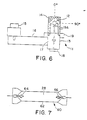
- Lamp 11 is an electrodeless lamp which is powered by microwave energy.
- Bulb 12 which contains a high pressure fill, and is made of quartz or other suitable material, is supported in a microwave cavity, which is comprised of conductive housing 13 and mesh 14.
- Magnetron 15 generates microwave energy, which is fed by waveguide 16, to coupling slot 17 microwave cavity.
- the mesh is metallic, and is constructed so that it is substantially opaque to microwave energy, while being substantially transparent to the light which is emitted by bulb 12.
- the bulb is rotated by rotator 18, and the bulb envelope is cooled by gas which is fed in to plenum 19 and out through nozzles 19A.
- FIG. 7 A further embodiment of a lamp is shown in Figure 7.
- This is an arc lamp 60 which is comprised of quartz envelope 62 having electrodes 64 and 66, and containing fill 28. To excite the fill, an A.C. voltage is impressed across the electrodes, whereupon an arc discharge occurs therebetween.
- the fill contains a sulfur or selenium containing substance which is present at a high pressure of at least about 1 bar (1 atmosphere) and preferably in the range of about 2 to 20 bar (2-20 atmospheres).
- Electrodes 64 and 66 are made of or plated with a special material, to prevent chemical reactions with the fill gas which may lead to electrode deterioration.
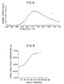
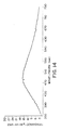
- the sulfur and selenium containing lamps described herein radiate a molecular spectrum in the visible region.
- a representative spectrum is depicted in Figure 8 and is seen to be smooth, with the sharp peaks which are characteristic of atomic spectra being notably absent.
- the spectrum shown in Figure 8 resulted when an electrodeless lamp such as is shown in Figure 6 having a bulb of spherical shape of internal diameter 2.84 cm was filled with .062 mg-moles/cc of sulfur and .08 bar of argon (60 torr) and was excited with microwave energy at a power density of about 280 watts/cc.
- a bulb with a spatially uniform color temperature would provide a better result. Additionally, the phenomenon of spatial "color separation" becomes more pronounced as the power level of the excitation energy decreases, either by virtue of dimming the lamp, or operating it at a lower power. It was also found that it may not be possible to dim the lamp as much as is desired, since the lamp may extinguish when a low power threshold is crossed.
- a substance is added to the bulb fill which has a low ionization potential.
- Such a substance has electrons which are loosely bound, thereby making them easy to dislodge. It has been found that when such a substance is added to the bulb fill, one or more of the uniformity of the color temperature, bulb extinguishing characteristics, and bulb starting characteristics, are improved.
- alkali metals One class of low ionization potential materials are the alkali metals, and it has been found that when an alkali metal containing substance is added to the fill, the following advantages result:
- the alkali metals may be used in either elemental or compound form, and one such substance which may be used is sodium.
- Other alkali metals are lithium, potassium, rubidium, and cesium.
- compounds in the form of halides or sulfides may be used, for example NaI, Na 2 S or LiI. Adding a sodium containing substance to the bulb fill may also have the effect of providing spectral emphasis in the red part of the spectrum.
- III B metals Another class of low ionization potential materials are the III B metals. It was found that when a III B metal containing substance was added to the fill, the color temperature of the emitted light become more uniform, and this is general true even at lower power densities. Furthermore, it is possible to operate the lamp at lower power levels without extinguishing.
- the III B metals include indium, thallium, gallium, aluminum, and may be used in elemental or compound form, for example combined as halides such as InI, TlI, TlBr, or combined as sulfides such as InS, Tl 2 Se, or Tl 2 S.
- a further grouping of low ionization materials are the alkaline earth or rare earth elements. Such substances cause the lamp to start more reliably.
- the alkaline earth metals are barium, beryllium, magnesium, calcium, strontium, and radium, and they may be used in elemental or compound forms, for example combined as halides such as CaBr 2 , BaI 2 , SrI 2 and sulfides, such as CaS, BaS, BaSe.
- the rare earth elements are yttrium, scandium, and lanthanum through lutetium. The improved starting is due to the low work functions of the alkaline earth and rare earth elements.
- the amount of the above-mentioned additives to be used to produce optimum results for different applications may vary.
- Na may be added in an amount of at least .001 mg/cc
- In may be added in an amount of at least .01 mg/cc
- Ba may be added in an amount of at least .005 mg/cc.
- Additives may produce spectral emphasis, so that the resultant spectrum may not be identical to that shown in Figure 8.
- mercury at least .1 mg/cc should be used.
- a bulb which is 2.84 cm in interior diameter was filled with 24 mg of S (2 mg/cc) and .08 bar (60 torr) of Ar, and operated at a suitably high power density.
- a figure of merit identified as "uniformity” is defined as the ratio of the minimum to maximum intensity of the light outputted by the bulb considering all angular positions except where the bulb is obstructed, e.g., by a narrow screen ring.
- the reason that the "uniformity" is a figure of merit representative of the color separation effect is that for lamps of this type, regions of lower color temperature also have lower output.
- the uniformity for the lamp was found to be .81.
- a lamp as described and operated in connection with Example I was filled with 24 mg of S (2 mg/cc), .08 bar (60 torr) of Ar, and .2 mg of NaI (.017 mg/cc) which contained .031 mg (.0026 mg/cc) of Na.
- the "uniformity" was .97, and a uniform color temperature around the angular extent of the bulb could be visually observed.
- a lamp as described and operated in connection with Example I was filled with 24 mg of S (2 mg/cc), .08 bar (60 torr) of Ar, and .3 mg of InI (.025 mg/cc) containing .143 mg (.012 mg/cc) of In.
- the "uniformity" was .91.
- a lamp as described and operated in connection with Example I was filled with 24 mg of S (2 mg/cc), .08 bar (60 torr) of argon, and 1 mg (.083 mg/cc) of BaS containing .81 mg (.068 mg/cc) of Ba or instead of the BaS, 7 mg of Hg. An improvement in the starting reliability of the lamp was observed.
- the volume (cc) refers to the volume of the light emitting gas rather than to the volume of the bulb.
- operating temperature is the temperature which is attained by the bulb during operation.
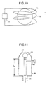
- FIG. 10 is an illustrative example of a lamp which is excited with electromagnetic energy in the radio frequency range.
- electromagnetic energy refers to both microwave and r.f. modes.
- r.f. source 70 generates r.f. power which is fed to induction coil 72, bulb 74, which houses a sulfur or selenium containing fill as described above also includes additives which may include an alkali halide containing substance or a III B metal containing substance as discussed above.
- r.f. energy from the induction coil 12 is coupled to the bulb fill, thereby exciting it to produce a spectrum in the visible range as previously described.
- the additives mentioned above permit operation at lower power densities, which in general is a significant advantage, and may be a particular advantage in the use of r.f. lamps.
- the invention may be applied to the different types of r.f. lamps, which include by way of non-limitative example, inductively and capacitively coupled lamps.
- the particular form of the electrodeless lamp heretofore described is exemplary only, and other specific shapes and types of cavities, for example, substantially all mesh type, as well as different types of coupling modes using one or more power sources, and one or more waveguides or other coupling modes may be used.
- Figure 11 illustrates a lamp wherein coupling is effected in a coaxial mode.
- Microwave power is provided to inner and outer conductors 82 and 84 for coupling to bulb 86.
- a conductive mesh 87 is connected to the outer conductor.
- a tuning element 88 may be provided to help in starting the lamp.
- Figure 12 depicts a further embodiment which is powered by r.f. or microwave power. Power from high frequency power source 104 is coupled to inner conductor 107 and outer conductor 106, which is a conductive mesh, the bulb 101 is supported between inner conductive member 107A and inner conductive member 107B.
- the embodiment shown in Figure 12 may be considered to be a form of capacitive coupling.
- the sulfur and selenium containing lamps described herein radiate a molecular spectrum in the visible region.
- a representative spectrum is smooth, with the sharp peaks which are characteristic of atomic spectra being notably absent.
- FIG. 13 depicts an embodiment of the invention wherein electrodeless lamp 110 is shown which has a fill wherein a sulfur containing substance or a selenium containing substance is the primary radiating component, as described above.
- Bulb 112 is secured in approximately spherical reflector 114 by bulb stem 115.
- the bulb stem may be arranged for rotation while streams of cooling fluid are directed at the bulb, to effect cooling (not shown).
- a mesh 116 contains microwave energy while allowing the emitted light to escape. Microwave energy is fed to the cavity via waveguide 118, and is coupled thereto through slot 119.
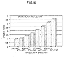
- reflector 114 is approximately spherical in shape. This causes the light to be reflected by the reflector back into the bulb. The resultant light which is re-emitted from the bulb is stronger in higher wavelengths than in the case where light is not reflected back into the bulb.
- Spectral measurements were taken for the case where the inside of reflector 114 is blackened, so as to be nonreflective, and the case where the reflector is shiny.
- the bulb was 2 cm in inner diameter and was filled with 2 mg/cc of elemental sulfur and .08 bar (60 torr) of argon, and was excited at a power density of about 325 watts/cc.
- selective wavelengths may be reflected back into the bulb to cause the lamp to emit a spectrum which is more equivalent to the spectrum radiated by a black body.
- this may be effected with the use of dichroic reflectors in either discrete form, or disposed directly on the bulb in the form of a coating.
- the output in the green region of the spectrum may be substantially cut, for example by a factor of 2.
- the output in the red region of the spectrum increases.
- a lamp having a spectrum produced by a sulfur fill modified as described above will emit more nearly like a black body.
- Figure 17, which is a 1931 chromaticity diagram.
- Figure 18 shows an embodiment of the invention using a dichroic reflector/filter such as described above.
- the dichroic reflector 130 is disposed on spherical bulb 92 which is located in reflector 134 which is closed by mesh 36.
- a dichroic reflector may be comprised of alternating layers of materials having different indices of refraction.
- a dichroic reflector comprised of 5 sets of alternating layers of zirconium oxide and silicon dioxide using layers 67.5 and 89 nm thick, respectively, may be used.
- the thickness and number of layers may be varied to change the spectral band which is reflected.
- the spectral output of the lamp may be tailored for particular applications by reflecting back selected wavelengths into the bulb.
- a lamp in which green radiation is reflected back may be used for horticultural applications such as for plant growth as in greenhouses.
- the spectrum of the sulfur-based lamp is inherently high in green wavelengths, and these are attenuated by the dichroic filter, while the red wavelengths, which are useful in inducing plant growth are increased. Wavelengths other than green may be reflected back to produce different resultant spectral outputs.
Landscapes
- Physics & Mathematics (AREA)
- Engineering & Computer Science (AREA)
- Plasma & Fusion (AREA)
- Electromagnetism (AREA)
- General Physics & Mathematics (AREA)
- Discharge Lamps And Accessories Thereof (AREA)
- Vessels And Coating Films For Discharge Lamps (AREA)
- Discharge Lamp (AREA)
- Lighting Device Outwards From Vehicle And Optical Signal (AREA)
Applications Claiming Priority (12)
| Application Number | Priority Date | Filing Date | Title |
|---|---|---|---|
| US60448790A | 1990-10-25 | 1990-10-25 | |
| US77971891A | 1991-10-23 | 1991-10-23 | |
| US86755192A | 1992-04-13 | 1992-04-13 | |
| US867551 | 1992-04-13 | ||
| US87576992A | 1992-04-29 | 1992-04-29 | |
| US875769 | 1992-04-29 | ||
| US88241092A | 1992-05-13 | 1992-05-13 | |
| US88240992A | 1992-05-13 | 1992-05-13 | |
| US882409 | 1992-05-13 | ||
| US97116792A | 1992-11-04 | 1992-11-04 | |
| US971167 | 1992-11-04 | ||
| EP93909308A EP0636275B1 (fr) | 1990-10-25 | 1993-04-13 | Lampe a caracteristiques spectrales regulables |
Related Parent Applications (1)
| Application Number | Title | Priority Date | Filing Date |
|---|---|---|---|
| EP93909308A Division EP0636275B1 (fr) | 1990-10-25 | 1993-04-13 | Lampe a caracteristiques spectrales regulables |
Publications (2)
| Publication Number | Publication Date |
|---|---|
| EP1003204A2 true EP1003204A2 (fr) | 2000-05-24 |
| EP1003204A3 EP1003204A3 (fr) | 2001-10-10 |
Family
ID=27569851
Family Applications (2)
| Application Number | Title | Priority Date | Filing Date |
|---|---|---|---|
| EP99120957A Withdrawn EP1003204A3 (fr) | 1990-10-25 | 1993-04-13 | Lampe à caracteristiques controlables |
| EP93909308A Expired - Lifetime EP0636275B1 (fr) | 1990-10-25 | 1993-04-13 | Lampe a caracteristiques spectrales regulables |
Family Applications After (1)
| Application Number | Title | Priority Date | Filing Date |
|---|---|---|---|
| EP93909308A Expired - Lifetime EP0636275B1 (fr) | 1990-10-25 | 1993-04-13 | Lampe a caracteristiques spectrales regulables |
Country Status (9)
| Country | Link |
|---|---|
| EP (2) | EP1003204A3 (fr) |
| JP (2) | JPH07509336A (fr) |
| AT (1) | ATE350762T1 (fr) |
| AU (1) | AU3977193A (fr) |
| CA (1) | CA2133344A1 (fr) |
| DE (1) | DE69334099T2 (fr) |
| HU (1) | HU217160B (fr) |
| RU (1) | RU2125322C1 (fr) |
| WO (1) | WO1993021655A1 (fr) |
Cited By (2)
| Publication number | Priority date | Publication date | Assignee | Title |
|---|---|---|---|---|
| EP1158567A3 (fr) * | 2000-05-26 | 2002-01-16 | Matsushita Electric Industrial Co., Ltd. | Dispositif de service pour une lampe à décharge à haute intensité exempte de mercure et lampe aux halogènures métalliques sans mercure |
| EP2747125A3 (fr) * | 2012-12-18 | 2014-10-22 | LG Electronics, Inc. | Dispositif d'éclairage sans électrode et son procédé de fabrication |
Families Citing this family (35)
| Publication number | Priority date | Publication date | Assignee | Title |
|---|---|---|---|---|
| US5798611A (en) * | 1990-10-25 | 1998-08-25 | Fusion Lighting, Inc. | Lamp having controllable spectrum |
| US5834895A (en) * | 1990-10-25 | 1998-11-10 | Fusion Lighting, Inc. | Visible lamp including selenium |
| JPH09503883A (ja) * | 1993-10-15 | 1997-04-15 | フュージョン ライティング, インコーポレイテッド | テルルランプ |
| US5914564A (en) * | 1994-04-07 | 1999-06-22 | The Regents Of The University Of California | RF driven sulfur lamp having driving electrodes which face each other |
| US5723943A (en) * | 1994-11-10 | 1998-03-03 | Atto Instruments, Inc. | Methods and apparatuses for high-speed control of lamp intensities and/or wavelengths and for high-speed optical data transmission |
| IL117972A (en) * | 1995-04-21 | 1999-06-20 | Fusion Lighting Inc | Compact microwave lamp |
| US5864210A (en) * | 1995-08-24 | 1999-01-26 | Matsushita Electric Industrial Co., Ltd. | Electrodeless hid lamp and electrodeless hid lamp system using the same |
| GB9522686D0 (en) * | 1995-11-06 | 1996-01-10 | Jenton R A & Co Ltd | Ultraviolet bulb |
| US5818167A (en) * | 1996-02-01 | 1998-10-06 | Osram Sylvania Inc. | Electrodeless high intensity discharge lamp having a phosphorus fill |
| US6031333A (en) * | 1996-04-22 | 2000-02-29 | Fusion Lighting, Inc. | Compact microwave lamp having a tuning block and a dielectric located in a lamp cavity |
| US6291936B1 (en) | 1996-05-31 | 2001-09-18 | Fusion Lighting, Inc. | Discharge lamp with reflective jacket |
| PL331378A1 (en) * | 1996-05-31 | 1999-07-05 | Fusion Lighting | Multiple-reflection electrode-free sulphur- or selenium-filled lamp and method of generating radiation using such lamp |
| US5838108A (en) * | 1996-08-14 | 1998-11-17 | Fusion Uv Systems, Inc. | Method and apparatus for starting difficult to start electrodeless lamps using a field emission source |
| US5833360A (en) * | 1996-10-17 | 1998-11-10 | Compaq Computer Corporation | High efficiency lamp apparatus for producing a beam of polarized light |
| TW406280B (en) | 1997-05-21 | 2000-09-21 | Fusion Lighting Inc | non-rotating electrodeless lamp containing molecular fill |
| US6137237A (en) | 1998-01-13 | 2000-10-24 | Fusion Lighting, Inc. | High frequency inductive lamp and power oscillator |
| US6313587B1 (en) | 1998-01-13 | 2001-11-06 | Fusion Lighting, Inc. | High frequency inductive lamp and power oscillator |
| WO1999065052A1 (fr) | 1998-06-12 | 1999-12-16 | Fusion Lighting, Inc. | Lampe a rendu de couleurs ameliore |
| KR100393817B1 (ko) * | 2001-09-27 | 2003-08-02 | 엘지전자 주식회사 | 무전극 조명기기 |
| KR20030037653A (ko) * | 2001-11-07 | 2003-05-14 | 엘지전자 주식회사 | 소형화된 무전극 조명기기 |
| RU2231166C2 (ru) * | 2001-11-23 | 2004-06-20 | Эл Джи Электроникс Инк. | Безэлектродное осветительное устройство с колпаком |
| US7268495B2 (en) * | 2005-01-21 | 2007-09-11 | General Electric Company | Ceramic metal halide lamp |
| GB201011786D0 (en) * | 2010-07-13 | 2010-08-25 | Ceravision Ltd | Plasma light source |
| KR101241049B1 (ko) | 2011-08-01 | 2013-03-15 | 주식회사 플라즈마트 | 플라즈마 발생 장치 및 플라즈마 발생 방법 |
| KR101246191B1 (ko) | 2011-10-13 | 2013-03-21 | 주식회사 윈텔 | 플라즈마 장치 및 기판 처리 장치 |
| KR101332337B1 (ko) | 2012-06-29 | 2013-11-22 | 태원전기산업 (주) | 초고주파 발광 램프 장치 |
| KR20150089183A (ko) | 2014-01-27 | 2015-08-05 | 엘지전자 주식회사 | 무전극 조명장치 |
| KR20150089184A (ko) | 2014-01-27 | 2015-08-05 | 엘지전자 주식회사 | 무전극 조명장치 |
| US9502149B2 (en) * | 2014-08-11 | 2016-11-22 | Nordson Corporation | Ultraviolet systems and methods for irradiating a substrate |
| CN106876244A (zh) * | 2015-12-11 | 2017-06-20 | 李昆达 | 无电极灯 |
| RU172286U1 (ru) * | 2017-02-13 | 2017-07-04 | Федеральное государственное унитарное предприятие "Всероссийский электротехнический институт" (ФГУП ВЭИ) | Осветительное устройство |
| RU2687074C1 (ru) * | 2018-05-07 | 2019-05-07 | Общество с ограниченной ответственностью "Торговый дом Загар" | Способ расширения зоны эффективного излучения ртутных ламп |
| RU2693870C1 (ru) * | 2018-10-11 | 2019-07-05 | Общество с ограниченной ответственностью "Торговый дом Загар" | Способ дифференцированной форсировки вывода на рабочий уровень мощности светового потока при включении ртутных ламп |
| RU2761182C1 (ru) * | 2020-09-22 | 2021-12-06 | Ооо "Спецоптопродукция" | Способ повышения кпд газоразрядной лампы и управления спектром ее излучения |
| RU204177U1 (ru) * | 2020-12-30 | 2021-05-13 | Федеральное государственное унитарное предприятие "Российский Федеральный Ядерный Центр - Всероссийский Научно-Исследовательский Институт Технической Физики имени академика Е.И. Забабахина" (ФГУП "РФЯЦ-ВНИИТФ им. академ. Е.И. Забабахина") | Осветительное устройство |
Citations (3)
| Publication number | Priority date | Publication date | Assignee | Title |
|---|---|---|---|---|
| JPS5231583A (en) * | 1975-09-05 | 1977-03-10 | Toshiba Corp | Lamp discharging metallic fumes |
| JPS63224193A (ja) * | 1987-03-11 | 1988-09-19 | 株式会社日立製作所 | 光源装置 |
| US4945290A (en) * | 1987-10-23 | 1990-07-31 | Bbc Brown Boveri Ag | High-power radiator |
Family Cites Families (11)
| Publication number | Priority date | Publication date | Assignee | Title |
|---|---|---|---|---|
| US3234421A (en) * | 1961-01-23 | 1966-02-08 | Gen Electric | Metallic halide electric discharge lamps |
| NL7107535A (fr) * | 1971-06-02 | 1972-12-05 | ||
| US3748520A (en) * | 1972-05-05 | 1973-07-24 | Gen Telephone & Elect | Electric discharge lamp having a fill including niobium pentaiodide complexed with an inorganic oxo-compound as the primary active component |
| GB2023923B (en) * | 1978-05-22 | 1982-06-30 | Commw Scient Ind Res Org | Atomic spectral lamp |
| NL7901897A (nl) * | 1979-03-09 | 1980-09-11 | Philips Nv | Elektrodeloze gasontladingslamp. |
| SU886099A1 (ru) * | 1980-04-08 | 1981-11-30 | Всесоюзный Научно-Исследовательский Проектно-Конструкторский И Технологический Институт Источников Света Им. А.Н.Лодыгина | Металлогалогенна лампа |
| JPS62272448A (ja) * | 1986-05-21 | 1987-11-26 | Agency Of Ind Science & Technol | 紫外線照射装置 |
| US4978891A (en) * | 1989-04-17 | 1990-12-18 | Fusion Systems Corporation | Electrodeless lamp system with controllable spectral output |
| US4974227A (en) * | 1989-10-16 | 1990-11-27 | Nippon Seiko Kabushiki Kaisha | Low-pressure mercury resonance radiation source |
| SU1705918A1 (ru) * | 1990-02-22 | 1992-01-15 | Научно-Технический Центр Научно-Технического Творчества Молодежи "Поиск" | Безртутна металлогалогенна лампа |
| DK0554350T3 (da) * | 1990-10-25 | 1997-09-22 | Fusion Systems Corp | Lampe med høj effekt |
-
1993
- 1993-04-13 AU AU39771/93A patent/AU3977193A/en not_active Abandoned
- 1993-04-13 RU RU94046059/09A patent/RU2125322C1/ru not_active IP Right Cessation
- 1993-04-13 HU HU9402942A patent/HU217160B/hu not_active IP Right Cessation
- 1993-04-13 EP EP99120957A patent/EP1003204A3/fr not_active Withdrawn
- 1993-04-13 DE DE69334099T patent/DE69334099T2/de not_active Expired - Fee Related
- 1993-04-13 EP EP93909308A patent/EP0636275B1/fr not_active Expired - Lifetime
- 1993-04-13 AT AT93909308T patent/ATE350762T1/de not_active IP Right Cessation
- 1993-04-13 WO PCT/US1993/003417 patent/WO1993021655A1/fr not_active Ceased
- 1993-04-13 CA CA002133344A patent/CA2133344A1/fr not_active Abandoned
- 1993-04-13 JP JP5518532A patent/JPH07509336A/ja active Pending
-
2002
- 2002-10-30 JP JP2002316476A patent/JP2003187743A/ja active Pending
Patent Citations (3)
| Publication number | Priority date | Publication date | Assignee | Title |
|---|---|---|---|---|
| JPS5231583A (en) * | 1975-09-05 | 1977-03-10 | Toshiba Corp | Lamp discharging metallic fumes |
| JPS63224193A (ja) * | 1987-03-11 | 1988-09-19 | 株式会社日立製作所 | 光源装置 |
| US4945290A (en) * | 1987-10-23 | 1990-07-31 | Bbc Brown Boveri Ag | High-power radiator |
Cited By (4)
| Publication number | Priority date | Publication date | Assignee | Title |
|---|---|---|---|---|
| EP1158567A3 (fr) * | 2000-05-26 | 2002-01-16 | Matsushita Electric Industrial Co., Ltd. | Dispositif de service pour une lampe à décharge à haute intensité exempte de mercure et lampe aux halogènures métalliques sans mercure |
| US6608444B2 (en) | 2000-05-26 | 2003-08-19 | Matsushita Electric Industrial Co., Ltd. | Mercury-free high-intensity discharge lamp operating apparatus and mercury-free metal halide lamp |
| EP2747125A3 (fr) * | 2012-12-18 | 2014-10-22 | LG Electronics, Inc. | Dispositif d'éclairage sans électrode et son procédé de fabrication |
| US9620352B2 (en) | 2012-12-18 | 2017-04-11 | Lg Electronics Inc. | Electrodeless lighting device and method for manufacturing the same |
Also Published As
| Publication number | Publication date |
|---|---|
| DE69334099T2 (de) | 2007-08-09 |
| JPH07509336A (ja) | 1995-10-12 |
| ATE350762T1 (de) | 2007-01-15 |
| WO1993021655A1 (fr) | 1993-10-28 |
| RU2125322C1 (ru) | 1999-01-20 |
| JP2003187743A (ja) | 2003-07-04 |
| EP0636275A1 (fr) | 1995-02-01 |
| EP0636275B1 (fr) | 2007-01-03 |
| DE69334099D1 (de) | 2007-02-15 |
| HU9402942D0 (en) | 1995-02-28 |
| EP1003204A3 (fr) | 2001-10-10 |
| HUT68508A (en) | 1995-06-28 |
| AU3977193A (en) | 1993-11-18 |
| HU217160B (hu) | 1999-11-29 |
| CA2133344A1 (fr) | 1993-10-28 |
Similar Documents
| Publication | Publication Date | Title |
|---|---|---|
| US5773918A (en) | Lamp with light reflection back into bulb | |
| EP0636275B1 (fr) | Lampe a caracteristiques spectrales regulables | |
| US6072268A (en) | Lamp apparatus and method for re-using waste light | |
| US5606220A (en) | Visible lamp including selenium or sulfur | |
| US5834895A (en) | Visible lamp including selenium | |
| CA2093921C (fr) | Lampe a haute puissance | |
| US5864210A (en) | Electrodeless hid lamp and electrodeless hid lamp system using the same | |
| US5113119A (en) | High pressure gas discharge lamp | |
| US4992700A (en) | Reprographic metal halide lamps having high blue emission | |
| KR100348610B1 (ko) | 금속 할로겐 무전극 램프 | |
| EP0724768B1 (fr) | Lampe a tellure | |
| US5925981A (en) | Tellurium lamp | |
| US5818167A (en) | Electrodeless high intensity discharge lamp having a phosphorus fill | |
| US6633111B1 (en) | Electrodeless lamp using SnI2 | |
| JP4464156B2 (ja) | プラズマランプシステム及びそれに用いられるバルブ | |
| EP0788140B1 (fr) | Lampe à décharge de haut intensité sans électrode comportant un remplissage au sulfure de bore | |
| US7825598B2 (en) | Mercury-free discharge compositions and lamps incorporating Titanium, Zirconium, and Hafnium | |
| JP3196647B2 (ja) | 無電極高圧放電ランプ | |
| Dobrusskin et al. | Mercury and Metal Halide Lamps1 | |
| JP2011108654A (ja) | 調光中の色度ドリフトを制御するためフィルターを有するガス放電ランプ及び方法 |
Legal Events
| Date | Code | Title | Description |
|---|---|---|---|
| PUAI | Public reference made under article 153(3) epc to a published international application that has entered the european phase |
Free format text: ORIGINAL CODE: 0009012 |
|
| 17P | Request for examination filed |
Effective date: 19991103 |
|
| AC | Divisional application: reference to earlier application |
Ref document number: 636275 Country of ref document: EP |
|
| AK | Designated contracting states |
Kind code of ref document: A2 Designated state(s): DE FR GB IT NL SE Kind code of ref document: A2 Designated state(s): AT BE CH DE DK ES FR GB GR IE IT LI LU MC NL PT SE |
|
| PUAL | Search report despatched |
Free format text: ORIGINAL CODE: 0009013 |
|
| AK | Designated contracting states |
Kind code of ref document: A3 Designated state(s): DE FR GB IT NL SE |
|
| RIC1 | Information provided on ipc code assigned before grant |
Free format text: 7H 01J 65/04 A, 7H 01J 61/02 B, 7H 01J 61/12 B, 7H 01J 61/35 B |
|
| AKX | Designation fees paid |
Free format text: AT BE CH DE DK ES FR GB GR IE IT LI LU MC NL PT SE |
|
| 17Q | First examination report despatched |
Effective date: 20050117 |
|
| STAA | Information on the status of an ep patent application or granted ep patent |
Free format text: STATUS: THE APPLICATION IS DEEMED TO BE WITHDRAWN |
|
| 18D | Application deemed to be withdrawn |
Effective date: 20101103 |