EP1003258A1 - Elektrische Stromschiene mit Frontbuchse zur Verbindung von mehreren Stromschienen - Google Patents
Elektrische Stromschiene mit Frontbuchse zur Verbindung von mehreren Stromschienen Download PDFInfo
- Publication number
- EP1003258A1 EP1003258A1 EP99120026A EP99120026A EP1003258A1 EP 1003258 A1 EP1003258 A1 EP 1003258A1 EP 99120026 A EP99120026 A EP 99120026A EP 99120026 A EP99120026 A EP 99120026A EP 1003258 A1 EP1003258 A1 EP 1003258A1
- Authority
- EP
- European Patent Office
- Prior art keywords
- conductor rail
- sockets
- frontal
- top surface
- socket
- Prior art date
- Legal status (The legal status is an assumption and is not a legal conclusion. Google has not performed a legal analysis and makes no representation as to the accuracy of the status listed.)
- Withdrawn
Links
- 239000004020 conductor Substances 0.000 title claims abstract description 35
- 230000037431 insertion Effects 0.000 claims description 6
- 238000003780 insertion Methods 0.000 claims description 6
- 229910052751 metal Inorganic materials 0.000 claims description 6
- 239000002184 metal Substances 0.000 claims description 6
- 229910000978 Pb alloy Inorganic materials 0.000 claims description 2
- 229910001128 Sn alloy Inorganic materials 0.000 claims description 2
- 239000011248 coating agent Substances 0.000 claims description 2
- 238000000576 coating method Methods 0.000 claims description 2
- 230000000630 rising effect Effects 0.000 claims description 2
- 229910052709 silver Inorganic materials 0.000 claims description 2
- 239000004332 silver Substances 0.000 claims description 2
- 239000000463 material Substances 0.000 claims 1
- 210000002105 tongue Anatomy 0.000 description 3
- 230000007774 longterm Effects 0.000 description 2
- ATJFFYVFTNAWJD-UHFFFAOYSA-N Tin Chemical compound [Sn] ATJFFYVFTNAWJD-UHFFFAOYSA-N 0.000 description 1
- 238000009434 installation Methods 0.000 description 1
- 238000004519 manufacturing process Methods 0.000 description 1
- 239000000203 mixture Substances 0.000 description 1
- 238000005728 strengthening Methods 0.000 description 1
Images



Classifications
-
- H—ELECTRICITY
- H01—ELECTRIC ELEMENTS
- H01R—ELECTRICALLY-CONDUCTIVE CONNECTIONS; STRUCTURAL ASSOCIATIONS OF A PLURALITY OF MUTUALLY-INSULATED ELECTRICAL CONNECTING ELEMENTS; COUPLING DEVICES; CURRENT COLLECTORS
- H01R13/00—Details of coupling devices of the kinds covered by groups H01R12/70 or H01R24/00 - H01R33/00
- H01R13/02—Contact members
- H01R13/10—Sockets for co-operation with pins or blades
- H01R13/11—Resilient sockets
- H01R13/115—U-shaped sockets having inwardly bent legs, e.g. spade type
-
- H—ELECTRICITY
- H01—ELECTRIC ELEMENTS
- H01R—ELECTRICALLY-CONDUCTIVE CONNECTIONS; STRUCTURAL ASSOCIATIONS OF A PLURALITY OF MUTUALLY-INSULATED ELECTRICAL CONNECTING ELEMENTS; COUPLING DEVICES; CURRENT COLLECTORS
- H01R31/00—Coupling parts supported only by co-operation with counterpart
- H01R31/08—Short-circuiting members for bridging contacts in a counterpart
- H01R31/085—Short circuiting bus-strips
-
- H—ELECTRICITY
- H02—GENERATION; CONVERSION OR DISTRIBUTION OF ELECTRIC POWER
- H02B—BOARDS, SUBSTATIONS OR SWITCHING ARRANGEMENTS FOR THE SUPPLY OR DISTRIBUTION OF ELECTRIC POWER
- H02B1/00—Frameworks, boards, panels, desks, casings; Details of substations or switching arrangements
- H02B1/20—Bus-bar or other wiring layouts, e.g. in cubicles, in switchyards
- H02B1/205—Bus-bar or other wiring layouts, e.g. in cubicles, in switchyards for connecting electrical apparatus mounted side by side on a rail
Definitions
- the present invention relates to an electrical conductor rail as described in the introduction to claim 1.
- Such conductor rails are notably used in electrical supply networks in which currents of the order of several amperes are carried at a voltage of several hundred volts.
- the safety systems to be included in such installations usually comprise a series of automatic safety devices which take the form of plug-in modules arranged on a connection board in an electrical junction box.
- plug-in modules arranged on a connection board in an electrical junction box.
- the conductor rails, mounted horizontally are connected to one another via vertically mounted busbar.
- the conductor rails and the vertical busbar possess plugs at their connection points. Electrical connection of the plugs and therefore the rails is effected by means of electrical sockets.
- connection sockets of types known hitherto have not always proved capable of meeting all the requirements imposed upon them, as regards contact resistance and long-term reliability in particular.
- the present invention is intended to improve electrical conductor rails of the type described above in the introduction in such a manner that they offer a high level of long-term reliability and low contact resistance in addition to low manufacturing cost.
- Figure 1 shows a frame 2 with two conductor rails 1. It is also possible to include several conductor rails. To the right and to the left of conductor rail 1 there is sufficient space to place a connection bar in order to provide an electrical connection between the conductor rails.
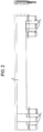
- the solution to the efficient use of the space available is provided by a connection bar 3 as shown in figure 2.
- This connection bar comprises, as does conductor rail 1, three metal sheets isolated electrically from each other and possessing a plug 4 at each end of the metal strip in such a manner that the plugs are placed side by side at the two ends of the connection bar and across its longitudinal axis.
- Figure 3 shows two conductor rails 1 connected one to the other by a connection bar 3. It can be seen in figure 3 that there are on the right-hand side of each conductor rail three frontal sockets 5, each placed parallel to the others, which are intended to receive the plugs 4.
- Figure 4 shows in more precise terms the composition of the frontal sockets in cross-section (left-hand view) and in longitudinal section (right-hand view).
- the socket shown in figure 4 comprises two parts.
- the first part 6 is a piece of sheet metal forming a single continuous part with the conductor rail and bent to form a tube in such a manner that the longitudinal edges, seen in the direction of insertion, of the metal sheet almost meet at a point approximately in line with the central vertical longitudinal plane of the socket.
- the result is a product in the form of a tube whose upper surface is flat and whose sides possess an approximately semi-circular cross-sectional profile.
- the area at the bottom of this part is also approximately flat and parallel to the top surface of the "tube", with the exception of the ridge 7 rising inwards on the central vertical axis of the socket.
- This ridge may be replaced, in one variant of the invention, by tongues folded down to provide local strengthening of the socket.
- the insertion end of the socket may be advantageously arranged in a manner such as it projects slightly above the surrounding surface and is bevelled (on both sides or on one side only), in order to facilitate the insertion of the plug connection pin.
- a top spring 8 is fitted around this first part of the socket, tightly surrounding the bottom and the sides of the first part and forming, around the top of the latter, pressure arms 9 and 10 which differ, seen in the direction of insertion, in their front and rear halves.
- a pressure arm with a stepped profile is shaped in stepped form directly on each side of the top spring 8.
- the termination area connecting to the free end of this arm is curved in such a manner that it presses flat against the top surface of a male connection pin 4, applying a degree of pressure when the connection pin is introduced into the socket.
- the stepped configuration of the pressure arm 10 in the rear area 12 of the top spring allows rigid, tensioned mounting of the top spring 8 on the first part 6 of the connection socket. To achieve this, the terminations of the pressure arm 10 press down on the top surface of the first tubular part.
- Tongues are stamped out in the sides and extend in approximately a straight line from the top spring 8, are bent slightly inwards and their terminations are directed away from the entrance of the socket sleeve. These tongues provide a further electrical contact with the connection pin in a manner such that the pin is pressed into contact at all points in an optimum fashion with the socket. In order to reduce still further the contact resistance of this connection of plug and socket type, it is advantageous to cover the socket sleeves and the connection pins with a fine coating of silver or a highly conductive tin/lead alloy.
- connection pin which is very flat, and consequently of limited thickness, and which allows connection by introduction from the side in the same plane as the busbar conductors.
Landscapes
- Engineering & Computer Science (AREA)
- Power Engineering (AREA)
- Installation Of Bus-Bars (AREA)
- Connector Housings Or Holding Contact Members (AREA)
- Coupling Device And Connection With Printed Circuit (AREA)
Applications Claiming Priority (2)
| Application Number | Priority Date | Filing Date | Title |
|---|---|---|---|
| FR9813100 | 1998-10-19 | ||
| FR9813100A FR2784813B1 (fr) | 1998-10-19 | 1998-10-19 | Rail de contact comprenant des douilles femelles frontales pour relier entre eux plusieurs rails de contact |
Publications (1)
| Publication Number | Publication Date |
|---|---|
| EP1003258A1 true EP1003258A1 (de) | 2000-05-24 |
Family
ID=9531745
Family Applications (1)
| Application Number | Title | Priority Date | Filing Date |
|---|---|---|---|
| EP99120026A Withdrawn EP1003258A1 (de) | 1998-10-19 | 1999-10-18 | Elektrische Stromschiene mit Frontbuchse zur Verbindung von mehreren Stromschienen |
Country Status (3)
| Country | Link |
|---|---|
| EP (1) | EP1003258A1 (de) |
| DE (1) | DE29905003U1 (de) |
| FR (1) | FR2784813B1 (de) |
Cited By (3)
| Publication number | Priority date | Publication date | Assignee | Title |
|---|---|---|---|---|
| WO2003067725A1 (de) * | 2002-02-07 | 2003-08-14 | Abb Patent Gmbh | Anschluss- oder verteilvorrichtung für elektrische installationsgeräte |
| EP1630917A1 (de) * | 2004-08-24 | 2006-03-01 | Weidmüller Interface GmbH & Co. KG | Montage- und Anschluss-System für elektrische Geräte |
| EP1983622A1 (de) * | 2007-04-20 | 2008-10-22 | Siemens Aktiengesellschaft | Installationsverteiler mit Sammelschienenmodulen |
Families Citing this family (1)
| Publication number | Priority date | Publication date | Assignee | Title |
|---|---|---|---|---|
| DE20306230U1 (de) * | 2003-04-19 | 2003-07-17 | ABB Patent GmbH, 68526 Ladenburg | Sammelschienensystem für eine elektrische Installationsverteilung |
Citations (3)
| Publication number | Priority date | Publication date | Assignee | Title |
|---|---|---|---|---|
| US3660806A (en) * | 1970-10-07 | 1972-05-02 | Thomas & Betts Corp | Connector |
| DE3813099A1 (de) * | 1988-04-19 | 1989-11-02 | Asea Brown Boveri | Niederspannungsverteiler |
| WO1997049145A1 (de) * | 1996-06-17 | 1997-12-24 | Framatome Connectors International | Steckverbinderhülse |
-
1998
- 1998-10-19 FR FR9813100A patent/FR2784813B1/fr not_active Expired - Fee Related
-
1999
- 1999-03-18 DE DE29905003U patent/DE29905003U1/de not_active Expired - Lifetime
- 1999-10-18 EP EP99120026A patent/EP1003258A1/de not_active Withdrawn
Patent Citations (3)
| Publication number | Priority date | Publication date | Assignee | Title |
|---|---|---|---|---|
| US3660806A (en) * | 1970-10-07 | 1972-05-02 | Thomas & Betts Corp | Connector |
| DE3813099A1 (de) * | 1988-04-19 | 1989-11-02 | Asea Brown Boveri | Niederspannungsverteiler |
| WO1997049145A1 (de) * | 1996-06-17 | 1997-12-24 | Framatome Connectors International | Steckverbinderhülse |
Cited By (4)
| Publication number | Priority date | Publication date | Assignee | Title |
|---|---|---|---|---|
| WO2003067725A1 (de) * | 2002-02-07 | 2003-08-14 | Abb Patent Gmbh | Anschluss- oder verteilvorrichtung für elektrische installationsgeräte |
| US7092244B2 (en) | 2002-02-07 | 2006-08-15 | Abb Patent Gmbh | Connection or distributing device for electrical installation equipment |
| EP1630917A1 (de) * | 2004-08-24 | 2006-03-01 | Weidmüller Interface GmbH & Co. KG | Montage- und Anschluss-System für elektrische Geräte |
| EP1983622A1 (de) * | 2007-04-20 | 2008-10-22 | Siemens Aktiengesellschaft | Installationsverteiler mit Sammelschienenmodulen |
Also Published As
| Publication number | Publication date |
|---|---|
| FR2784813A1 (fr) | 2000-04-21 |
| DE29905003U1 (de) | 1999-06-02 |
| FR2784813B1 (fr) | 2000-12-15 |
Similar Documents
| Publication | Publication Date | Title |
|---|---|---|
| US3926498A (en) | Electrical connector and insulation-piercing contact member | |
| US5096442A (en) | Compact electrical connector | |
| EP0372768A1 (de) | Verbinder für zwei Stromschienen | |
| US4863393A (en) | Modular jack assembly with improved bridging arrangement | |
| GB2234866A (en) | Socket outlet for receiving a variety of plugs | |
| HU217389B (hu) | Áramköri lap, élre szerelt csatlakozóval ellátott áramköri lap, valamint eljárás elektromos csatlakozónak áramköri lap szélére való rászereléséhez | |
| US7384317B1 (en) | Multi-terminal block for electronic devices having superimposed conductor connecting levels | |
| DE3904391A1 (de) | Isolationsauftrenn-klemmenanordnung | |
| WO1996037012A1 (en) | Electrical connector including means for terminating wires | |
| GB2129628A (en) | Terminal block | |
| US10069223B2 (en) | Electrical cable connector | |
| NZ264477A (en) | Data cable plug connector with frequency shielding for high frequency cable connected to ground wire shield | |
| EP1107362A3 (de) | Elektrischer Verbinderanschlusskasten | |
| DE60104347T2 (de) | Steckverbinder | |
| US3768062A (en) | Terminal for flexible circuits | |
| CN209169411U (zh) | 一种直通式智能双进双出模块 | |
| EP0109297B1 (de) | Elektrische Kontaktorgane und Zusammenbau elektrischer Verbinder | |
| EP1003258A1 (de) | Elektrische Stromschiene mit Frontbuchse zur Verbindung von mehreren Stromschienen | |
| EP1237228A3 (de) | Verbindungsstecker | |
| CH695034A5 (de) | Steckverbindungsteil einer Steckverbindung fuer hochfrequente Datenuebertragung ueber elektrische Leiter. | |
| USRE31132E (en) | Electrical connector and insulation-piercing contact member | |
| JP4322387B2 (ja) | 電気開閉装置ユニットのための接続組立体 | |
| EP2751882A1 (de) | Steckverbindungsteil | |
| US4975067A (en) | Surface contact power connector | |
| EP0236860A2 (de) | Flachkabelendsteckverbinder |
Legal Events
| Date | Code | Title | Description |
|---|---|---|---|
| PUAI | Public reference made under article 153(3) epc to a published international application that has entered the european phase |
Free format text: ORIGINAL CODE: 0009012 |
|
| AK | Designated contracting states |
Kind code of ref document: A1 Designated state(s): AT BE CH CY DE DK ES FI FR GB GR IE IT LI LU MC NL PT SE |
|
| AX | Request for extension of the european patent |
Free format text: AL;LT;LV;MK;RO;SI |
|
| 17P | Request for examination filed |
Effective date: 20001026 |
|
| AKX | Designation fees paid |
Free format text: AT BE CH CY DE DK ES FI FR GB GR IE IT LI LU MC NL PT SE |
|
| RAP1 | Party data changed (applicant data changed or rights of an application transferred) |
Owner name: FCI |
|
| GRAP | Despatch of communication of intention to grant a patent |
Free format text: ORIGINAL CODE: EPIDOSNIGR1 |
|
| STAA | Information on the status of an ep patent application or granted ep patent |
Free format text: STATUS: THE APPLICATION IS DEEMED TO BE WITHDRAWN |
|
| 18D | Application deemed to be withdrawn |
Effective date: 20071117 |