EP1003260A1 - Einbaugehaüse mit ziehharmonikaartigen Falten, insbesondere für elektrisches Gerät und Herstellungsverfahren - Google Patents
Einbaugehaüse mit ziehharmonikaartigen Falten, insbesondere für elektrisches Gerät und Herstellungsverfahren Download PDFInfo
- Publication number
- EP1003260A1 EP1003260A1 EP99402805A EP99402805A EP1003260A1 EP 1003260 A1 EP1003260 A1 EP 1003260A1 EP 99402805 A EP99402805 A EP 99402805A EP 99402805 A EP99402805 A EP 99402805A EP 1003260 A1 EP1003260 A1 EP 1003260A1
- Authority
- EP
- European Patent Office
- Prior art keywords
- ring
- box according
- installation box
- side wall
- folds
- Prior art date
- Legal status (The legal status is an assumption and is not a legal conclusion. Google has not performed a legal analysis and makes no representation as to the accuracy of the status listed.)
- Withdrawn
Links
- 238000004519 manufacturing process Methods 0.000 title claims description 9
- 238000009434 installation Methods 0.000 claims description 16
- 238000000034 method Methods 0.000 claims description 5
- 238000007664 blowing Methods 0.000 claims description 3
- 210000001061 forehead Anatomy 0.000 claims 2
- 230000014759 maintenance of location Effects 0.000 abstract 1
- 230000008901 benefit Effects 0.000 description 5
- 208000031968 Cadaver Diseases 0.000 description 4
- 238000000465 moulding Methods 0.000 description 3
- 230000006835 compression Effects 0.000 description 2
- 238000007906 compression Methods 0.000 description 2
- 230000002452 interceptive effect Effects 0.000 description 2
- 241000861223 Issus Species 0.000 description 1
- 238000002347 injection Methods 0.000 description 1
- 239000007924 injection Substances 0.000 description 1
Images

Classifications
-
- H—ELECTRICITY
- H02—GENERATION; CONVERSION OR DISTRIBUTION OF ELECTRIC POWER
- H02G—INSTALLATION OF ELECTRIC CABLES OR LINES, OR OF COMBINED OPTICAL AND ELECTRIC CABLES OR LINES
- H02G3/00—Installations of electric cables or lines or protective tubing therefor in or on buildings, equivalent structures or vehicles
- H02G3/02—Details
- H02G3/08—Distribution boxes; Connection or junction boxes
- H02G3/12—Distribution boxes; Connection or junction boxes for flush mounting
- H02G3/121—Distribution boxes; Connection or junction boxes for flush mounting in plain walls
Definitions
- the ring of the mounting box according to the invention is then mobile between a deployed position, of maximum height, for which, engaged by its notch with that of the inner edges of the first fold of the body including its guard is closest, it adds its own height to that of the body, without a any of its folds is compressed, in a retracted position, by minimum height, for which, on the contrary, it is engaged, by its notch, with the inner edge of the last fold of the body from which its guard is farthest, thus keeping all the folds of this body compressed.
- the installers advantageously benefit from greater flexibility used for these built-in boxes, being able to adjust in height each of them whenever necessary.
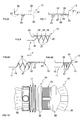
- the box embedding 10 comprises, overall, on the one hand, a body 11, of generally circular outline, and, on the other hand, rotatably mounted in this body 11, at the outlet 12 thereof, a ring 13, which, according to provisions described in more detail later, is suitable for allowing to subject any assembly, not shown, to the assembly to embed.
- the body 11 of this box 10 has a side wall 14 which is generally cylindrical, and a bottom 16.
- the side wall 14 of the body 11 forms, annularly, according to provisions described in more detail later, at least one pleat 17, which extends axially, and as it is better visible on Figure 4, between two inner edges 18 capable of being moved one by relative to the other, with, in the meantime, an outer edge 19 of diameter upper, and, jointly, the ring 13 is mounted axially movable in this body 11, by presenting a guard 20 for its support thereon, and it has, at least locally, projecting outwards on its side wall 22, at least one notch 23, which extends transversely over at least part its perimeter, and by which, according to provisions also described more in detail later, it is capable of hooking internally on the body 11.
- these folds 17 are contiguous, in the manner folds of an accordion.
- the folds 17 all have, axially, the same profile.
- the inner edges 18 of the pleats 17 are therefore each formed by a edge, and it is the same for their outer edge 19.
- the folds 17 thus formed by the side wall 14 of the body 11 have, at rest, a deployed configuration, and the inner edges 18 which delimit them are likely to be close to each other as it will appear below.
- the folds 17 of the body 11 affect the side wall 14 thereof at full thickness.
- the ring 13 is capable of being hooked by its notch 23 on any of the folds 17, and, more precisely, on one of the edges interiors 18 of such a fold 17.
- these notches 23 are joined, at the way of the teeth of a rack.
- these notches 23 have, axially, an asymmetrical profile, their front 25 closest to the guard 20 being stiffer than their front 26 furthest from it.
- their front 25 extends substantially perpendicular to the axis of the assembly.
- the crest 27 of these notches 23 is tangent to a cylindrical surface S'1 which is the same for all, and likewise their root 28 extends substantially along a surface cylindrical S "1 which is also the same for all.
- the diameter of the cylindrical surface S'1 is slightly greater than that of the cylindrical surface S1 along which the inner edges 18 of the folds 17 of the body 11, and, together, the diameter of the cylindrical surface S "1 is less than that of this cylindrical surface S1.
- the notches 23 of the ring 13 extend annularly around its side wall 22, on almost the entire periphery thereof.
- the ring 13 has, recessed on its side wall 22, and in diametrically positions opposite to each other, two grooves 30, which are elongated along generatrices of its side wall 22, locally interrupting its notches 23, and by virtue of each of which intervenes a clean screw 31 to the subjection of the built-in equipment.
- these grooves 30 are closed, at each of their ends, by transverse walls 32 in each from which the corresponding screw 31 bites.
- the folds 17 of the body 11 then each have their configuration deployed original, for which their inner edges 18 are axially spaced apart the other.
- the ring 13 can, step by step, i.e. tooth by tooth, occupy all positions stably desirable intermediaries between its extreme positions.
- the folds 17 of the body 11 are then more or less compressed, some can even remain in the deployed configuration, however others are already in retracted configuration.
- the installation box 10 can, for example, implement a method consisting in intervening by blowing, by bringing the body 11 from this mounting box 10 and its ring 13 of the same parison 34, as shown in FIG. 10.
- this parison 34 has connecting portions 36 which are to eliminate.
- the body 11 of the mounting box 10 and the ring 13 thereof are separated from the parison 34 which is common to them even before it is removed from the mold.
- the body 11 annularly comprises a cylindrical collar 38, the axial height of which can be more or less important.
- the folds provided according to the invention are all identical between them, these folds might as well be different from each other to others, especially for obtaining a compression stress variable for the wall with these folds.
- the notches of the ring associated might as well be different from each other other.
- the plies provided for according to the invention are molded naturally more easily for a more or less deployed configuration of these folds, as more particularly described and represented, one would not leave of the scope of the invention by carrying out this molding for a more configuration retracted from these folds, or even for a fully retracted configuration of these.
Landscapes
- Engineering & Computer Science (AREA)
- Architecture (AREA)
- Civil Engineering (AREA)
- Structural Engineering (AREA)
- Blow-Moulding Or Thermoforming Of Plastics Or The Like (AREA)
Applications Claiming Priority (2)
| Application Number | Priority Date | Filing Date | Title |
|---|---|---|---|
| FR9814527A FR2786329B1 (fr) | 1998-11-19 | 1998-11-19 | Boite d'encastrement a plis en accordeon, notamment pour appareillage electrique, et son procede de fabrication |
| FR9814527 | 1998-11-19 |
Publications (1)
| Publication Number | Publication Date |
|---|---|
| EP1003260A1 true EP1003260A1 (de) | 2000-05-24 |
Family
ID=9532905
Family Applications (1)
| Application Number | Title | Priority Date | Filing Date |
|---|---|---|---|
| EP99402805A Withdrawn EP1003260A1 (de) | 1998-11-19 | 1999-11-10 | Einbaugehaüse mit ziehharmonikaartigen Falten, insbesondere für elektrisches Gerät und Herstellungsverfahren |
Country Status (2)
| Country | Link |
|---|---|
| EP (1) | EP1003260A1 (de) |
| FR (1) | FR2786329B1 (de) |
Cited By (6)
| Publication number | Priority date | Publication date | Assignee | Title |
|---|---|---|---|---|
| EP1670112A1 (de) * | 2004-12-10 | 2006-06-14 | Abb B.V. | Elektro-Einbaudose |
| ES2375748A1 (es) * | 2009-01-14 | 2012-03-06 | Schneider Electric España, S.A. | Elemento separador para el montaje de bastidores de mecanismos eléctricos en cajas de empotrar. |
| WO2011113655A3 (de) * | 2010-03-18 | 2012-10-26 | Siemens Aktiengesellschaft | Elektroinstallationsverteiler |
| CN104937794A (zh) * | 2012-12-20 | 2015-09-23 | 勒格朗法国公司 | 能自动固定到壁上的嵌入式电箱 |
| NL2031636B1 (nl) * | 2022-04-20 | 2023-11-07 | Willem Adriaan Ten Donkelaar Mark | Een installatiedoos, een correctiedeel voor een installatiedoos en gietbouwwerkwijzen voor het in een bekisting vormen van een wand voorzien van een installatiedoos |
| US12638161B2 (en) | 2022-12-19 | 2026-05-26 | Erico International Corporation | Adjustable-depth assemblies for luminaires and other devices |
Citations (3)
| Publication number | Priority date | Publication date | Assignee | Title |
|---|---|---|---|---|
| FR2237331A1 (en) * | 1972-10-10 | 1975-02-07 | Bassani Spa | Electrical equipment wall embedded housing - has within it a movable ring onto which is screwed the electrical equipment |
| GB1467768A (en) * | 1974-05-14 | 1977-03-23 | Fawa | Junction box with at least one removable interconnecting member |
| DE2802893A1 (de) * | 1978-01-24 | 1979-07-26 | Bbc Brown Boveri & Cie | In wandungen versenkt einbaubarer geraetekasten |
-
1998
- 1998-11-19 FR FR9814527A patent/FR2786329B1/fr not_active Expired - Fee Related
-
1999
- 1999-11-10 EP EP99402805A patent/EP1003260A1/de not_active Withdrawn
Patent Citations (3)
| Publication number | Priority date | Publication date | Assignee | Title |
|---|---|---|---|---|
| FR2237331A1 (en) * | 1972-10-10 | 1975-02-07 | Bassani Spa | Electrical equipment wall embedded housing - has within it a movable ring onto which is screwed the electrical equipment |
| GB1467768A (en) * | 1974-05-14 | 1977-03-23 | Fawa | Junction box with at least one removable interconnecting member |
| DE2802893A1 (de) * | 1978-01-24 | 1979-07-26 | Bbc Brown Boveri & Cie | In wandungen versenkt einbaubarer geraetekasten |
Cited By (8)
| Publication number | Priority date | Publication date | Assignee | Title |
|---|---|---|---|---|
| EP1670112A1 (de) * | 2004-12-10 | 2006-06-14 | Abb B.V. | Elektro-Einbaudose |
| NL1027704C2 (nl) * | 2004-12-10 | 2006-06-19 | Abb Bv | Doos voor elektrische installaties. |
| ES2375748A1 (es) * | 2009-01-14 | 2012-03-06 | Schneider Electric España, S.A. | Elemento separador para el montaje de bastidores de mecanismos eléctricos en cajas de empotrar. |
| WO2011113655A3 (de) * | 2010-03-18 | 2012-10-26 | Siemens Aktiengesellschaft | Elektroinstallationsverteiler |
| CN104937794A (zh) * | 2012-12-20 | 2015-09-23 | 勒格朗法国公司 | 能自动固定到壁上的嵌入式电箱 |
| CN104937794B (zh) * | 2012-12-20 | 2017-09-22 | 勒格朗法国公司 | 能自动固定到壁上的嵌入式电箱 |
| NL2031636B1 (nl) * | 2022-04-20 | 2023-11-07 | Willem Adriaan Ten Donkelaar Mark | Een installatiedoos, een correctiedeel voor een installatiedoos en gietbouwwerkwijzen voor het in een bekisting vormen van een wand voorzien van een installatiedoos |
| US12638161B2 (en) | 2022-12-19 | 2026-05-26 | Erico International Corporation | Adjustable-depth assemblies for luminaires and other devices |
Also Published As
| Publication number | Publication date |
|---|---|
| FR2786329A1 (fr) | 2000-05-26 |
| FR2786329B1 (fr) | 2001-02-09 |
Similar Documents
| Publication | Publication Date | Title |
|---|---|---|
| FR2827420A1 (fr) | Dispositif de fixation pour des detecteurs tels que des capteurs de proximite | |
| LU86192A1 (fr) | Moule pour bandages pneumatiques | |
| WO1998052264A1 (fr) | Dispositif d'entree de cable | |
| FR2786329A1 (fr) | Boite d'encastrement a plis en accordeon, notamment pour appareillage electrique, et son procede de fabrication | |
| EP0829931A1 (de) | Elektrischer Drehschalter, insbesondere für Fahrzeuge | |
| EP2692598B1 (de) | Verbindungsvorrichtung zwischen einem Wischerarm und einem Scheibenwischerelement | |
| EP1452793B1 (de) | Ausrüstungshalterung und ihr Formverfahren | |
| EP0667669A1 (de) | Bürstenträger für elektrische Maschine | |
| EP1926916B1 (de) | Entfernbares flügelrad für einen ventilator | |
| EP2053193A1 (de) | Rollo | |
| EP1071182A1 (de) | Isoliergehäuse für eines Gerät anzubringen auf einen Kabelkanal über einem Träger | |
| EP0923176B1 (de) | Greifhalter für Einbaudose und entsprechende Einbaudose | |
| FR2623024A1 (fr) | Connecteur auto-denudant pour conducteur electrique isole | |
| EP0873907B1 (de) | Befestigungsring für eine unterhalb des Lenkrads eines Kraftfahrzeugs angeordnete Steuereinheit | |
| EP1021659A1 (de) | Bowdenzug für kraftfahrzeugsausrüstung | |
| FR2725146A1 (fr) | Procede pour realiser une liaison sertie entre un insert et une piece tubulaire | |
| EP0378476A1 (de) | Dose mit ausbrechbaren Öffnungen für Einbaugeräte, insbesondere für elektrische Geräte | |
| EP0064453B1 (de) | Handleuchte für Glühlampen mit festangebrachtem Schutzkorb und demontierbarer Fassung | |
| FR2753575A1 (fr) | Contacteur tournant a ruban, notamment pour vehicules automobiles | |
| WO2000033437A1 (fr) | Accessoire de fixation pour mecanisme d'appareillage a assujettir au socle d'une goulotte | |
| FR2825585A1 (fr) | Egrappoir a vendange et procede l'utilisant | |
| FR3028822A1 (fr) | Element de carter d'un boitier de motorisation pour un essuie-glace | |
| FR2715617A1 (fr) | Projecteur de véhicule, comportant des moyens perfectionnés de montage d'un correcteur de l'inclinaison du réflecteur. | |
| FR2763436A1 (fr) | Dispositif d'entree de cable | |
| FR2600121A1 (fr) | Verin pneumatique, notamment pour la commande d'un volet interpose dans un circuit de climatisation de vehicule automobile |
Legal Events
| Date | Code | Title | Description |
|---|---|---|---|
| PUAI | Public reference made under article 153(3) epc to a published international application that has entered the european phase |
Free format text: ORIGINAL CODE: 0009012 |
|
| AK | Designated contracting states |
Kind code of ref document: A1 Designated state(s): AT DE ES |
|
| AX | Request for extension of the european patent |
Free format text: AL;LT;LV;MK;RO;SI |
|
| 17P | Request for examination filed |
Effective date: 20000603 |
|
| AKX | Designation fees paid |
Free format text: AT DE ES |
|
| RAP1 | Party data changed (applicant data changed or rights of an application transferred) |
Owner name: LEGRAND SNC Owner name: LEGRAND FRANCE |
|
| 17Q | First examination report despatched |
Effective date: 20071130 |
|
| STAA | Information on the status of an ep patent application or granted ep patent |
Free format text: STATUS: THE APPLICATION IS DEEMED TO BE WITHDRAWN |
|
| 18D | Application deemed to be withdrawn |
Effective date: 20090929 |