EP1003263A1 - Dispositif de protection différentielle - Google Patents
Dispositif de protection différentielle Download PDFInfo
- Publication number
- EP1003263A1 EP1003263A1 EP99410135A EP99410135A EP1003263A1 EP 1003263 A1 EP1003263 A1 EP 1003263A1 EP 99410135 A EP99410135 A EP 99410135A EP 99410135 A EP99410135 A EP 99410135A EP 1003263 A1 EP1003263 A1 EP 1003263A1
- Authority
- EP
- European Patent Office
- Prior art keywords
- signal
- threshold
- differential
- protection device
- current
- Prior art date
- Legal status (The legal status is an assumption and is not a legal conclusion. Google has not performed a legal analysis and makes no representation as to the accuracy of the status listed.)
- Granted
Links
- 238000001514 detection method Methods 0.000 claims abstract description 22
- 239000004020 conductor Substances 0.000 claims description 28
- 230000010354 integration Effects 0.000 claims description 28
- 230000001360 synchronised effect Effects 0.000 claims description 19
- 230000010363 phase shift Effects 0.000 claims description 9
- 230000000903 blocking effect Effects 0.000 claims description 4
- 238000005259 measurement Methods 0.000 claims 1
- 239000013598 vector Substances 0.000 description 11
- 238000010586 diagram Methods 0.000 description 10
- 238000004804 winding Methods 0.000 description 8
- 238000005520 cutting process Methods 0.000 description 6
- 230000001939 inductive effect Effects 0.000 description 6
- 238000009434 installation Methods 0.000 description 5
- 238000009413 insulation Methods 0.000 description 5
- 230000000295 complement effect Effects 0.000 description 4
- 239000003990 capacitor Substances 0.000 description 3
- 238000010616 electrical installation Methods 0.000 description 2
- 238000001914 filtration Methods 0.000 description 2
- 230000001960 triggered effect Effects 0.000 description 2
- 238000002347 injection Methods 0.000 description 1
- 239000007924 injection Substances 0.000 description 1
- 238000012806 monitoring device Methods 0.000 description 1
- 230000011664 signaling Effects 0.000 description 1
- 239000000243 solution Substances 0.000 description 1
- 230000001052 transient effect Effects 0.000 description 1
Images

Classifications
-
- H—ELECTRICITY
- H02—GENERATION; CONVERSION OR DISTRIBUTION OF ELECTRIC POWER
- H02H—EMERGENCY PROTECTIVE CIRCUIT ARRANGEMENTS
- H02H3/00—Emergency protective circuit arrangements for automatic disconnection directly responsive to an undesired change from normal electric working condition with or without subsequent reconnection ; integrated protection
- H02H3/26—Emergency protective circuit arrangements for automatic disconnection directly responsive to an undesired change from normal electric working condition with or without subsequent reconnection ; integrated protection responsive to difference between voltages or between currents; responsive to phase angle between voltages or between currents
- H02H3/32—Emergency protective circuit arrangements for automatic disconnection directly responsive to an undesired change from normal electric working condition with or without subsequent reconnection ; integrated protection responsive to difference between voltages or between currents; responsive to phase angle between voltages or between currents involving comparison of the voltage or current values at corresponding points in different conductors of a single system, e.g. of currents in go and return conductors
- H02H3/33—Emergency protective circuit arrangements for automatic disconnection directly responsive to an undesired change from normal electric working condition with or without subsequent reconnection ; integrated protection responsive to difference between voltages or between currents; responsive to phase angle between voltages or between currents involving comparison of the voltage or current values at corresponding points in different conductors of a single system, e.g. of currents in go and return conductors using summation current transformers
- H02H3/337—Emergency protective circuit arrangements for automatic disconnection directly responsive to an undesired change from normal electric working condition with or without subsequent reconnection ; integrated protection responsive to difference between voltages or between currents; responsive to phase angle between voltages or between currents involving comparison of the voltage or current values at corresponding points in different conductors of a single system, e.g. of currents in go and return conductors using summation current transformers avoiding disconnection due to reactive fault currents
Definitions
- Differential protection devices are generally used to monitor or protect loads or parts of an electrical installation against current leaks to earth or a ground in the installation. This leakage current is manifested in particular by a differential or zero sequence current in main supply conductors.
- the differential current is detected by devices that determine the vector sum of the currents flowing in the main conductors feed.
- the devices for determining differential current comprise toroids having a magnetic circuit which surrounds said main conductors.
- the toroids have a secondary winding providing a signal representative of the current differential. This signal is generally applied to actuators, such as in particular trip relays, signaling relays, processing circuits or, for example, display devices.
- a differential current exceeds, for example, a predetermined threshold, the earth leakage protection opens the main contacts of the circuit breakers or differential switches, or signals this threshold being exceeded.
- Current leaks producing a differential current are generally in phase with the supply voltage main conductors. For example, when the devices are used for personal protection or to detect insulation faults, leakage currents can pass through essentially resistive loads.
- impeding loads other than resistive loads can cause leakage currents between main conductors and the earth or earth of an installation.
- electrical devices may have connected filtering devices between supply conductors and a grounding conductor. These devices filtering generally include inductors and capacitors which generate leakage currents with phase shifts due to the capacitive or inductive components of impedances they cross. Capacitive leakage currents can also be generated by line capacities formed between the main conductors and the earth of an installation.
- the leakage current detected by the devices differential increases and the trigger threshold may be exceeded.
- These currents capacitive or inductive then disturb the operation of the triggering devices differentials by making them sensitive to disturbing leakage currents which are not representative of insulation faults. These disturbances are particularly frequent when the trigger threshold is very low, for example, when the device is used for the protection of persons against direct contact.
- Certain insulation monitoring devices include means for separating real and imaginary components. However, such devices require means of important processing, and additional signal injection circuits in the network. Of plus these control devices do not apply to the same uses as the devices differential protection.
- the object of the invention is a differential protection device less sensitive to currents disruptive leakage.
- the first processing means include electronic circuits to operate at own current
- the second processing means have electronic circuits to operate with a power supply supplied by a power circuit.
- the processing unit comprises selection means connected between the first and second processing means and the actuator means for selecting the trigger signals supplied by said first and second processing means.
- the synchronous detection means comprise means for detecting sign to detect the sign of a signal representative of a voltage of the network conductors electric.
- the second processing means include means for blocking signal connected between integration means and comparison means.
- the first and second synchronous detection means operate alternately interleaved according to the sign of a signal representative of a voltage of the conductors of the electrical network.
- the second processing means include control means connected to the first and second comparison means and having an output providing a trigger signal when said first and second means of comparison detect that a threshold has been exceeded.
- the first and second processing means include a threshold of variable trip according to the phase shift of a differential fault current by relative to a signal representative of a voltage of the conductors of the electrical network, the threshold of variable trigger that can vary between the second predetermined threshold and the first threshold predetermined.
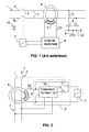
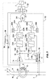
- the diagram in FIG. 1 shows a differential protection device of the type known to own current installed on a network 1 to be protected.
- the differential protection device has main contacts 2 to interrupt the current in conductors main 3 of the network.
- a current transformer 4 has a magnetic circuit which surrounds all the conductors of the network. This current transformer detects the differential current flowing in the conductors of an installation to be protected. If a fault appears, the transformer generates in a secondary winding 5 a current proportional to the leakage current in the main conductors.
- the winding secondary 5 is connected to an electronic processing circuit 6.
- This processing circuit controls a trip relay 7 when the secondary current representative of a fault exceeds a predetermined threshold for a predetermined time. Relay 7 of tripping causes the main contacts to open 2.
- capacitive loads 8 in particular capacitors lines or to capacitors arranged in supply filters, can derive a capacitive current Ic between the conductors 3 and a ground 9 or an earth conductor 10. This current le is then detected as a leakage current by the torus and the processing unit can trigger control of relay 7 and opening of contacts 2, even if the leak does not constitute not a danger for the installation or people.
- capacitive or inductive currents caused in particular by filters, do not are not representative of direct contact by a person or of an insulation fault. These currents are derived to the ground conductor or ground. In addition, as long as the mass is connected to earth, they do not present any real dangers in the event of indirect ground contacts by one person. Resistive currents or currents in phase or in opposite phase with the voltage are representative of an insulation fault or of direct contact by a person. Therefore, a differential protection device must therefore be very effective for the protection of this type of fault.
- a device protection comprises a first device for processing providing a trip order when the amplitude of the differential current exceeds a first predetermined threshold, and a second processing device providing a tripping order when the resistive component of the differential current exceeds one second predetermined threshold, the second threshold being less than the first threshold.
- the processing unit includes a first diode 11 connected between the secondary winding 5 of the torus 4 and the relay 7 for realize the first treatment device.
- the first threshold is carried out by the tripping threshold of relay 7.
- the device opens contacts 2.
- the relay reacts to the amplitude of the current whatever the phase of the current in relation to the network voltage.
- the relay threshold representative of the first threshold is preferably high. It corresponds, for example, to a differential fault current on the network of the order of 100 mA or more.
- the device of FIG. 2 comprises a second processing device 12 connected to the secondary 5 and reacting to the resistive or real component of the differential current.
- This second device comprises means for extracting the resistive or real component from the differential fault current represented by the ID signal.
- the resistive component is compared to a second trigger threshold of value lower than the first threshold. The protection of persons is then very effectively ensured, in particular against direct contacts.
- the second threshold can be low, for example of the order of 10 mA.
- An output of the device 12 providing a trigger signal is connected through a diode 13 at relay 7 trigger.
- the diodes 12 and 13 forming an "OR" gate at diodes that allow triggering if the first or second of the processing devices provides a trigger signal.
- either the current passing through the diode 11 is sufficient to trigger the relay, i.e. a signal supplied by the device 12 crosses diode 12 to control the relay.
- the device 12 has an input receiving a signal representative of the network voltage, for example, by a signal representative of the phase or sign of said tension.
- a device in fig 3, comprises a second processing device 12 comprising an amplifier 14 receiving a signal supplied by the secondary winding 5 and a synchronous detector connected to an output of said amplifier.
- the synchronous detector comprises a synchronized switch 15 controlled by a voltage sign detection device 16 of the distribution network 3.
- the detector 16 therefore provides a control signal 17 for control, depending on the phase of the mains voltage, switch 15 and the switching of a signal 18 supplied by the amplifier 15.
- a chopped signal 19 is supplied to an integrator 20 which integrates the signal 19 for each cutting period.
- an integration signal 21 is supplied to a blocker 22 for storing a signal 23 representative of the value of the end of integration.
- the memorization is kept until the next period corresponding to the end of the next integration.
- Signals 21 and 23 are representative of the real part of the signal supplied by the secondary winding 5 and therefore of the resistive component of a fault.
- the value stored is applied to a comparison device 24.
- the comparison device 24 of FIG. 3 makes it possible to compare the positive and negative memorized signals.
- the detector synchronous allows to detect a negative or positive alternation of a fault current since the switch is closed for half a period of the period corresponding to the network frequency.
- a first comparator 25 compares the signal 23 provided by the blocker 22 and the integrator 20 at a second positive threshold 26, and if an alternation negative is detected, a second comparator 27 compares the signal 23 with a second threshold negative 28.
- a comparison signal 26 goes to the valid high state, likewise if signal 23 is negative and if it becomes below the negative threshold 28, the signal 29 goes high.
- the second positive or negative thresholds, respectively 26 and 28 have the same value in absolute values. It is also possible, in other embodiments, to straighten signal 23 and to use only one comparator with a single first threshold, for example the first positive threshold.
- a timing circuit 30 connected to the comparison operates a timer to avoid unwanted trips or random.
- the output of the timing circuit provides a trigger signal 31 for control relay 7.
- the trigger signal 31 passes through a selection device 32 which functions as an "OR" door.
- the device 32 includes an "OR" with diodes operating in the same way as diodes 11 and 13.
- the second processing device 12 of FIG. 3 comprises a supply circuit 33 for supply the electronic circuits that compose it.
- the first processing device comprises a component 34 with voltage threshold connected between winding 5 and the relay through the selection device 32.
- the first processing device operates at own current without power supply.
- the voltage threshold of component 34 participates in the value of first predetermined threshold.
- the first device processing circuit may include a processing circuit 35 connected between the output of the amplifier 14 and the relay 7 through the selection device 32.
- the circuit 35 includes a pretreatment circuit 36 which may include a rectifier and a filter receiving the signal 18 representative of the current supplied by secondary 5 and providing a signal 37 to a comparator 38.
- Comparator 38 compares signal 37 to a first threshold 39 and provides a trigger signal at relay 7 through device 32.
- Processing circuit 35 is sensitive to a signal representative of the amplitude of the fault current.
- the component 34 and the device 35 can be part of the same first device for treatment with first identical or different thresholds.
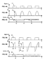
- FIG. 4a illustrates the sign signal 17 changing value each time alternating network voltage.
- FIG. 4b illustrates the signal 19 cut according to the value of the signal 17.
- signal 19 is substantially in phase with signal 17, therefore a fault current is essentially resistive.
- a fault appears to a instant tl substantially in the middle of synchronization.
- the integration of this signal gives a low value of signal 23 at an instant t2 at the end of integration shown in FIG. 4c.
- Has a instant t3 the fault persists and full integration over half a period can begin.
- FIG. 5A illustrates the signal 19 cut according to the phase of signal 17.
- signal 19 has a positive part 40 and a negative part 41.
- the integration of such a signal gives a low or zero value if the signal 19 is perfectly in 90 ° phase shift from signal 17.
- the signal is somewhat offset, the positive part is a little larger than the negative part. So it has a strong capacitive component and weak resistive component.
- Figure 5B shows the signals 23 and 26 at inputs of comparator 25.
- the signal 19 appears at a time t6 substantially in the middle of a synchronization signal 17.
- the signal 19 has substantially a quarter of a period is a positive half-cycle.
- a second synchronization period begins.
- the signal includes a part negative 41 then a positive part 40.
- an integration of the two parts provides a lower value of signal 23, at time t9, at the end of integration.
- the device does not produce tripping thanks to the timing circuit 30.
- Signal 23 could also have exceeded threshold 26 in the time interval t7 to t9, but the tripping of relay 7 would not have taken place thanks to tempo 30.
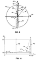
- Figure 6 shows a trigger and non-trigger diagram of a device according to one embodiment of the invention.
- the real or resistive part a differential current is carried on a horizontal axis 42
- the imaginary or reactive part for example capacitive or inductive, is carried on a vertical axis 43.
- the first threshold predetermined is, in this case, represented by a circle 44. It symbolizes the comparison with a threshold independent of the phase of the current.
- the second predetermined threshold is represented on this diagram by two vertical lines 45 and 46 arranged on each side and parallel to axis 43.
- vectors 47, 48, 49 and 50 representing differential fault currents allow to illustrate four cases of operation of a device according to this embodiment of the invention.
- the vector 47 exceeds the line 45 but does not exceed the circle 44, therefore the protection device will trigger by exceeding a second threshold 45 sensitive to the resistive part of a fault current. It is the second processing device 12 which gives a trigger signal.
- Vector 48 has a length greater than vector 47 but it does not do not exceed lines 45 or 46, nor circle 44.
- the resistive component of vector 48 is low, the capacitive component is high but it does not exceed the first threshold shown for circle 44.
- a current represented by a vector 48 does not produce tripping.
- the vector 49 has a weak resistive part which does not exceed lines 45 or 46 but has a very high capacitive part.
- the first threshold sensitive to the amplitude of the differential fault current is exceeded.
- the vector 50 exceeds line 46 and circle 44, so the first and second thresholds are exceeded and both processing devices give a trigger signal.
- the non-tripping of the protection device is in an area 51 limited by the lines 45 and 46 for the resistive part of the fault current and by arcs of circles 52 and 53 connecting lines 45 and 46 for the imaginary or reactive part of the fault current.
- This non-tripping zone 51 is hatched in the diagram in FIG. 6. Outside of this zone 51 a trigger occurs. Operation in the left or right side of the axis 43 depends on the directions of passage of the wires N and P in the torus 4 relative to the connection of the sign detector to the network 3.
- the operation in the left or right part of axis 43 also depends on the directions of passage of the wires N and P in the torus 4 relative to the connection of the sign detector on the network 3.
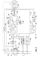
- Figure 7 shows a third embodiment of the invention.
- This embodiment has the advantage of quickly and safely detecting the presence of differential faults resistive.
- this embodiment allows a faster tripping time, even when the fault has an asymmetrical appearance or offset with respect to the voltage of the network.
- the second processing device 12 of FIG. 7 comprises a first synchronous detector represented by a first switch 15A controlled by a first signal 17A supplied by the sign detector 16, and a second switch 15B controlled by a second signal 17B supplied by said detector 16, said second signal being complementary to said first signal supplied by the detector16.
- the first switch 15A receives the signal 18 supplied by the amplifier 14 and provides a chopped signal 19A to an integrator 20A.
- An integrated signal 21A is then stored in a blocker 22A which supplies a signal 23A to a comparator 25A.
- the second switch 15B also receives the signal 18 and cuts in a complementary manner or interleaved said signal 18.
- the switch 15B provides a cut signal 19B to a integrator 20B, then an integrated signal 21B is supplied by the integrator to a blocker 22B which supplies a signal 23B to a comparator 25B.
- Comparators 25A and 25B compare signals 23A and 23B respectively with thresholds 26A and 26B respectively.
- the outputs of the comparators are connected to an AND gate 54 which provides a trigger signal 31 when the two comparators have detected a threshold crossing.
- the timing circuit 30 is no longer necessary to eliminate unwanted triggers.
- the first processing circuit has a voltage threshold component 34 composed of a thyristor 55 connected between winding 5 and relay 7 through diode 11. Thyristor 55 is triggered by a diode of zener type 56 having a voltage threshold which participates in the value of the first threshold of triggering of the first treatment device.
- the selection circuit 32 makes a diode OR with the diodes 11 and 13 to supply the relay 7 the trigger signals of the first and second processing devices.
- FIGS. 8A to 8D illustrate signals of a device according to FIG. 7 in a case of triggering by a second processing device 12.
- FIG. 8A shows signals 17A and 17B synchronization and switch cutting control 15A and 15B respectively.
- FIG. 8B shows a cut signal 19A, a blocked signal 23A and a threshold signal 26A.
- FIG. 8C shows a signal 19B cut so complementary or interleaved with respect to signal 19A, a blocked signal 23B and a signal threshold 26B.
- FIG. 8D shows the outputs of the comparators 25A and 25B and a signal trigger 31 produced by the second processing device 12.
- the comparator 25A then switches to a state representative of a threshold being exceeded (FIG. 8D). Between time t12 and time t13, a signal 19B has almost complete alternation. This signal is integrated and, at time t13, the integration value of the blocked signal 23B, exceeds the threshold 26B in negative value. The comparator 25B switches to its position representative of a threshold crossing. Since signal 23A was kept blocked, the two comparators are tilted and the AND gate 54 having its two active inputs provides a signal trigger 31 ( Figure 8D).
- the trigger occurs after a duration corresponding to substantially two alternations or half-period of the network, a little more than said period. If the frequency of network is 50 Hz, the trigger time in this case is a little more than 20 ms.
- the integration of part of an alternation can cause the threshold to be exceeded.
- the time to trigger may be even shorter, for example, greater than the duration of a half-cycle and less than the duration of two alternations, ie less than the duration of a complete period. In all cases, the trigger will be greater than the duration of an alternation or half a period because two consecutive half-wave signals are needed to trigger.
- FIGS. 9A, 9B and 9C illustrate signals according to FIG. 7 in a case of non-triggering by a second processing device 12.
- the signal 18 representing a signal of fault comprises a strong capacitive component and a weak resistive component.
- FIG. 9A shows complementary signals 17A and 17B.
- Figure 9B illustrates a signal 19A, signal 23A and threshold signal 26A.
- FIG. 9C illustrates a signal 19B, a signal 23B and signal 26B.
- a signal 19A appears for the duration of the cutting control command of the signal 17A.
- the signal 19A is integrated until an instant t15 of end of cutting and integration.
- the integration signal is blocked and its value is kept by a signal 23A. Since signal 19A had a unique polarity, in this case positive, the signal 23A is higher than the threshold 26A and the comparator 25A switches to detection of exceeding of threshold.
- the signal 18 is cut to give a signal 19B.
- This strong signal capacitive component has a positive part 57 and a negative part 58. These parts 57 and 58 are offset by the integration of the signal 19B and the blocked value 23B at the end integration at a time t16 is low and does not exceed the threshold 26B in negative value. Therefore, the comparator 25B does not switch to detection of threshold crossing. Then enter instant tl6 and instant t17, the chopped signal 19A also has two parts 59 and 60 of polarities different. At the end of integration (instant t17) the blocking signal 23A takes on a new value, below threshold 26A. In this case, the comparator 25A switches back to the non-detection position threshold.
- comparators 25A and 25B are preferably comparators with window that toggles if the threshold crossing occurs in absolute values, for example, greater than a positive threshold for a positive signal or less than a negative threshold for a signal negative.
- An embodiment of such a comparator is given for example in the association comparators 25 and 27 of FIG. 3.
- Other solutions can consist in rectifying the signals 23A and 23B before being applied to comparators 25A and 25B.
- the threshold triggering when the currents have resistive and reactive components (capacitive or inductive), the threshold triggering varies with these components.
- Figure 10 shows a representative curve 61 of the variation of the triggering threshold as a function of the phase shift of the fault current by with respect to the voltage, the phase shift being representative of the components of the current in particular real and imaginary or resistive or reactive parts.
- the triggering threshold is equal to the overshoot a threshold S2 representative of the second predetermined threshold of the second processing device 12. If the phase shift increases, the threshold also increases up to a first threshold S1 which can be independent of the phase shift, the threshold S1 being representative of the exceeding of the first threshold of the first processing device.
- threshold S2 corresponds to lines 45 and 46 and threshold S1 corresponds to circle 44 of FIG. 6.
- the curve 61 also defines a limit between a triggering zone upper part and a non-triggering zone 51 in the lower part of the curve.
- the vectors 47, 48, 49 and 50 are also placed in Figure 10 to illustrate the operation.
- differential protection devices described above can be realized with electronic, analog, digital or combination circuits.
- some functions can advantageously be performed in a programmed form, with a microprocessor or microcontroller associated with an analog-digital converter.
- the sign detection circuits 16 and the supply circuit 33 can be electrically isolated from the mains voltage 3.
- FIGS. 4A-C, 5A-C, 8A-D and 9A-C are given as example to illustrate embodiments of the invention. But other signals can also be representative of signals related to embodiments of the invention. Likewise the synchronous detection which is carried out by a controlled switch can be carried out by other means of synchronous detection.
Landscapes
- Engineering & Computer Science (AREA)
- Power Engineering (AREA)
- Emergency Protection Circuit Devices (AREA)
- Semiconductor Lasers (AREA)
- Facsimile Transmission Control (AREA)
- Power Steering Mechanism (AREA)
- Window Of Vehicle (AREA)
- Train Traffic Observation, Control, And Security (AREA)
- Transmitters (AREA)
Abstract
Description
- des moyens de mesure de courant différentiel pour fournir un signal représentatif d'un courant différentiel circulant dans des conducteurs d'un réseau électrique,
- une unité de traitement connectée aux moyens de mesure et fournissant un signal de déclenchement lorsqu'un courant différentiel dépasse un seuil prédéterminé, et
- des moyens actionneurs connectés à l'unité de traitement pour recevoir un signal de déclenchement,
- des premiers moyens de traitement recevant un signal représentatif du courant différentiel et fournissant un signal de déclenchement lorsque l'amplitude dudit courant différentiel dépasse un premier seuil prédéterminé, et
- des seconds moyens de traitement recevant un signal représentatif du courant différentiel et fournissant un signal de déclenchement lorsque la composante résistive du courant différentiel dépasse un second seuil prédéterminé, le second seuil prédéterminé étant inférieur au premier seuil prédéterminé.
- des premiers moyens de détection synchrone recevant un signal représentatif du courant différentiel et un signal représentatif d'une tension des conducteurs du réseau électrique,
- des premiers moyens intégration connectés aux premiers moyens de détection synchrone, et
- des premiers moyens comparaison connectés aux moyens intégrateurs pour comparer des signaux fournis par les moyens intégrateurs avec au moins une valeur de second seuil prédéterminé.
- des seconds moyens de détection synchrone recevant un signal représentatif du courant différentiel et un signal représentatif d'une tension des conducteurs du réseau électrique,
- des seconds moyens intégration connectés aux seconds moyens de détection synchrone, et
- des seconds moyens comparaison connectés aux seconds moyens intégrateurs pour comparer des signaux fournis par les seconds moyens intégrateurs avec au moins une valeur de second seuil prédéterminé.
- La figure 1 représente un schéma d'un dispositif de protection différentielle de l'art antérieur ;
- La figure 2 représente un schéma d'un dispositif de protection différentielle selon un premier mode de réalisation de l'invention ;
- La figure 3 représente un schéma d'un dispositif de protection différentielle selon un second mode de réalisation de l'invention ;
- Les figures 4A, 4B, 4C et 5A, 5B, 5C représentent des signaux dans un dispositif selon la figure 3 ;
- La figure 6 représente un diagramme illustrant les zones de déclenchement d'un dispositif de protection différentielle selon un mode de réalisation de l'invention ;
- La figure 7 représente un schéma d'un dispositif de protection différentielle selon un troisième mode de réalisation de l'invention ;
- Les figures 8A, 8B, 8C 8D et 9A, 9B, 9C représentent des signaux dans un dispositif selon la figure 7 ;
- La figure 10 représente une courbe représentative d'un seuil de déclenchement en fonction du déphasage du courant de défaut différentiel dans des dispositifs selon des modes de réalisation de l'invention.
Claims (10)
- Dispositif de protection différentielle comportant :dispositif caractérisé en ce que l'unité de traitement comporte :des moyens de mesure de courant différentiel (4, 5) pour fournir un signal (ID) représentatif d'un courant différentiel circulant dans des conducteurs d'un réseau électrique (1, 3),une unité de traitement (6) connectée aux moyens de mesure et fournissant un signal de déclenchement lorsqu'un courant différentiel dépasse un seuil prédéterminé, etdes moyens actionneurs (7) connectés à l'unité de traitement pour recevoir un signal de déclenchement,des premiers moyens de traitement (11, 7, 34, 35) recevant un signal représentatif du courant différentiel (ID) et fournissant un signal de déclenchement lorsque l'amplitude dudit courant différentiel dépasse un premier seuil prédéterminé (7, 34, 39, 56, S1, 44), etdes seconds moyens de traitement (12) recevant un signal représentatif du courant différentiel (ID) et fournissant un signal de déclenchement (31) lorsque la composante résistive du courant différentiel dépasse un second seuil prédéterminé (26, 28, 26A, 26B, 45, 46, S2), le second seuil prédéterminé étant inférieur au premier seuil prédéterminé.
- Dispositif de protection différentielle selon la revendication 1, caractérisé en ce que les premiers moyens de traitement comportent des circuits électroniques (34, 55, 56, 7) pour fonctionner à propre courant, et les seconds moyens de traitement comportent des circuits électroniques pour fonctionner avec une alimentation électrique fournie par un circuit d'alimentation (33).
- Dispositif de protection différentielle selon l'une des revendications 1 ou 2, caractérisé en ce que l'unité de traitement comporte des moyens de sélection (32) connectés entre les premiers et seconds moyens de traitement et les moyens actionneurs (7) pour sélectionner les signaux de déclenchement fournis par lesdits premiers et les seconds moyens de traitement.
- Dispositif de protection différentielle selon l'une quelconque des revendications 1 à 3, caractérisé en ce que les seconds moyens de traitement comportent :des premiers moyens de détection synchrone (15, 15A, 16) recevant un signal (18) représentatif du courant différentiel et un signal représentatif d'une tension des conducteurs du réseau électrique,des premiers moyens d'intégration (20, 20A) connectés aux premiers moyens de détection synchrone, etdes premiers moyens comparaison (24, 25, 25A, 27) connectés aux moyens intégrateurs pour comparer des signaux fournis par les moyens intégrateurs avec au moins une valeur de second seuil prédéterminé (26, 26A, 28).
- Dispositif de protection différentielle selon la revendication 4, caractérisé en ce que les moyens de détection synchrone comportent des moyens de détection de signe (16) pour détecter le signe d'un signal représentatif d'une tension des conducteurs du réseau électrique.
- Dispositif de protection différentielle selon l'une des revendications 4 ou 5, caractérisé en ce les seconds moyens de traitement comportent :des seconds moyens de détection synchrone (15B, 16) recevant un signal représentatif du courant différentiel et un signal représentatif d'une tension des conducteurs du réseau électrique,des seconds moyens d'intégration (20B) connectés aux seconds moyens de détection synchrone, etdes seconds moyens de comparaison (25B) connectés aux seconds moyens intégrateurs pour comparer des signaux fournis par les seconds moyens intégrateurs avec au moins une valeur de second seuil prédéterminé (26B).
- Dispositif de protection différentielle selon l'une quelconque des revendications 4 à 6, caractérisé en ce que les seconds moyens de traitement comportent des moyens de blocage de signal connectés entre des moyens d'intégration (20, 20A, 20B) et des moyens de comparaison (24, 25, 27, 25A, 25B).
- Dispositif de protection différentielle selon l'une des revendications 6 ou 7, caractérisé en ce que les premiers et les seconds moyens de détection synchrones (15A, 15B, 16) fonctionnent alternativement de manière entrelacée selon le signe (17A, 17B) d'un signal représentatif d'une tension des conducteurs du réseau électrique.
- Dispositif de protection différentielle selon l'une quelconque des revendications 6 à 8, caractérisé en ce que les seconds moyens de traitement comportent des moyens de contrôle (54) connectés aux premiers et seconds moyens de comparaison (25A, 25B) et comportant une sortie fournissant un signal de déclenchement (31) lorsque lesdits premiers et seconds moyens de comparaison détectent un dépassement de seuil.
- Dispositif de protection différentielle selon l'une quelconque des revendications 1 à 9, caractérisé en ce que les premiers et les seconds moyens de traitement comportent un seuil de déclenchement variable (61) en fonction du déphasage d'un courant de défaut différentiel par rapport à un signal représentatif d'une tension des conducteurs du réseau électrique, le seuil de déclenchement variable pouvant varier entre le second seuil prédéterminé (S2, 45, 46, 26, 28, 26A, 26B) et le premier seuil prédéterminé (S1, 34, 39, 44).
Applications Claiming Priority (2)
| Application Number | Priority Date | Filing Date | Title |
|---|---|---|---|
| FR9814681A FR2786040B1 (fr) | 1998-11-18 | 1998-11-18 | Dispositif de protection differentielle |
| FR9814681 | 1998-11-18 |
Publications (2)
| Publication Number | Publication Date |
|---|---|
| EP1003263A1 true EP1003263A1 (fr) | 2000-05-24 |
| EP1003263B1 EP1003263B1 (fr) | 2010-03-24 |
Family
ID=9533035
Family Applications (1)
| Application Number | Title | Priority Date | Filing Date |
|---|---|---|---|
| EP99410135A Expired - Lifetime EP1003263B1 (fr) | 1998-11-18 | 1999-10-15 | Dispositif de protection différentielle |
Country Status (4)
| Country | Link |
|---|---|
| EP (1) | EP1003263B1 (fr) |
| AT (1) | ATE462214T1 (fr) |
| DE (1) | DE69942169D1 (fr) |
| FR (1) | FR2786040B1 (fr) |
Cited By (1)
| Publication number | Priority date | Publication date | Assignee | Title |
|---|---|---|---|---|
| EP1475874A1 (fr) * | 2003-05-05 | 2004-11-10 | Schneider Electric Industries SAS | Dispositif et procédé de détection de défaut terre et relais comportant un tel dispositif |
Citations (1)
| Publication number | Priority date | Publication date | Assignee | Title |
|---|---|---|---|---|
| FR2538179A1 (fr) * | 1982-12-21 | 1984-06-22 | Merlin Gerin | Declencheur differentiel residuel a detection de variation d'etat |
-
1998
- 1998-11-18 FR FR9814681A patent/FR2786040B1/fr not_active Expired - Fee Related
-
1999
- 1999-10-15 EP EP99410135A patent/EP1003263B1/fr not_active Expired - Lifetime
- 1999-10-15 DE DE69942169T patent/DE69942169D1/de not_active Expired - Lifetime
- 1999-10-15 AT AT99410135T patent/ATE462214T1/de not_active IP Right Cessation
Patent Citations (1)
| Publication number | Priority date | Publication date | Assignee | Title |
|---|---|---|---|---|
| FR2538179A1 (fr) * | 1982-12-21 | 1984-06-22 | Merlin Gerin | Declencheur differentiel residuel a detection de variation d'etat |
Cited By (2)
| Publication number | Priority date | Publication date | Assignee | Title |
|---|---|---|---|---|
| EP1475874A1 (fr) * | 2003-05-05 | 2004-11-10 | Schneider Electric Industries SAS | Dispositif et procédé de détection de défaut terre et relais comportant un tel dispositif |
| FR2854741A1 (fr) * | 2003-05-05 | 2004-11-12 | Schneider Electric Ind Sas | Dispositif et procede de detection de defaut terre et relais comportant un tel dispositif |
Also Published As
| Publication number | Publication date |
|---|---|
| FR2786040A1 (fr) | 2000-05-19 |
| DE69942169D1 (de) | 2010-05-06 |
| FR2786040B1 (fr) | 2001-01-12 |
| EP1003263B1 (fr) | 2010-03-24 |
| ATE462214T1 (de) | 2010-04-15 |
Similar Documents
| Publication | Publication Date | Title |
|---|---|---|
| EP0407310B1 (fr) | Déclencheur statique comportant un système de désensibilisation de la protection terre | |
| EP0094871B1 (fr) | Relais électronique de détection d'arc | |
| EP1155488B1 (fr) | Declencheur electronique selectif | |
| EP0193435B1 (fr) | Circuit de commande d'alimentation à découpage à démarrage automatique | |
| EP3577672B1 (fr) | Dispositif de coupure de courant continu haute tension | |
| EP0019507A1 (fr) | Perfectionnement aux transformateurs capacitifs de tension à sortie électronique | |
| EP1845599A1 (fr) | Dispositif de détection d'arc électrique, dispositif de coupure comportant un tel dispositif et procédé de détection d'arc électrique | |
| CH621895A5 (fr) | ||
| EP0060790B1 (fr) | Perfectionnements aux disjoncteurs sensibles aux courants de fuite | |
| RU2546130C2 (ru) | Устройство и способ дифференциальной защиты и электрический прибор, содержащий такое устройство | |
| EP1003263B1 (fr) | Dispositif de protection différentielle | |
| EP3471228B1 (fr) | Dispositif et procédé de protection différentielle et appareil électrique comportant un tel dispositif | |
| EP3594699A2 (fr) | Dispositif de protection différentielle | |
| EP0180506B1 (fr) | Dispositif de sécurité pour appareil de protection différentielle | |
| FR2520165A1 (fr) | Interrupteur differentiel a usage domestique | |
| FR2538179A1 (fr) | Declencheur differentiel residuel a detection de variation d'etat | |
| EP3707796B1 (fr) | Dispositif de protection différentielle avec filtrage de la porteuse du signal d'excitation | |
| FR2775847A1 (fr) | Dispositifs de protection differentielle, appareil electrique et installation electrique comportant un tel dispositif | |
| EP0226520B1 (fr) | Procédé et dispositif de commande de l'alimentation de charges à partir d'un réseau triphasé | |
| EP0814555B1 (fr) | Dispositif de protection différentielle | |
| EP0357482A2 (fr) | Dispositif de protection d'un appareil électrique contre le vol | |
| WO2009144083A1 (fr) | Procede et systeme de detection d'un courant secondaire residuel dans un transformateur de courant dans un reseau electrique haute tension, et de detection de la formation d'un arc dans un disjoncteur | |
| EP1083644B1 (fr) | Dispositif de protection terre sensible à des courants d'arc, declencheur et disjoncteur comportant un tel dispositif | |
| EP0027757A1 (fr) | Dispositif de protection pour ligne d'énergie électrique | |
| EP0813283B1 (fr) | Dispositif de protection différentielle immunisé contre les déclenchements intempestifs |
Legal Events
| Date | Code | Title | Description |
|---|---|---|---|
| PUAI | Public reference made under article 153(3) epc to a published international application that has entered the european phase |
Free format text: ORIGINAL CODE: 0009012 |
|
| AK | Designated contracting states |
Kind code of ref document: A1 Designated state(s): AT BE CH CY DE DK ES FI FR GB GR IE IT LI LU MC NL PT SE |
|
| AX | Request for extension of the european patent |
Free format text: AL;LT;LV;MK;RO;SI |
|
| 17P | Request for examination filed |
Effective date: 20000624 |
|
| AKX | Designation fees paid |
Free format text: AT BE CH CY DE DK ES FI FR GB GR IE IT LI LU MC NL PT SE |
|
| RAP1 | Party data changed (applicant data changed or rights of an application transferred) |
Owner name: SCHNEIDER ELECTRIC INDUSTRIES SAS |
|
| RAP1 | Party data changed (applicant data changed or rights of an application transferred) |
Owner name: SCHNEIDER ELECTRIC INDUSTRIES SAS |
|
| GRAP | Despatch of communication of intention to grant a patent |
Free format text: ORIGINAL CODE: EPIDOSNIGR1 |
|
| GRAS | Grant fee paid |
Free format text: ORIGINAL CODE: EPIDOSNIGR3 |
|
| GRAA | (expected) grant |
Free format text: ORIGINAL CODE: 0009210 |
|
| AK | Designated contracting states |
Kind code of ref document: B1 Designated state(s): AT BE CH CY DE DK ES FI FR GB GR IE IT LI LU MC NL PT SE |
|
| REG | Reference to a national code |
Ref country code: GB Ref legal event code: FG4D Free format text: NOT ENGLISH |
|
| REG | Reference to a national code |
Ref country code: CH Ref legal event code: EP |
|
| REG | Reference to a national code |
Ref country code: IE Ref legal event code: FG4D |
|
| REF | Corresponds to: |
Ref document number: 69942169 Country of ref document: DE Date of ref document: 20100506 Kind code of ref document: P |
|
| REG | Reference to a national code |
Ref country code: NL Ref legal event code: VDEP Effective date: 20100324 |
|
| PG25 | Lapsed in a contracting state [announced via postgrant information from national office to epo] |
Ref country code: FI Free format text: LAPSE BECAUSE OF FAILURE TO SUBMIT A TRANSLATION OF THE DESCRIPTION OR TO PAY THE FEE WITHIN THE PRESCRIBED TIME-LIMIT Effective date: 20100324 Ref country code: AT Free format text: LAPSE BECAUSE OF FAILURE TO SUBMIT A TRANSLATION OF THE DESCRIPTION OR TO PAY THE FEE WITHIN THE PRESCRIBED TIME-LIMIT Effective date: 20100324 |
|
| REG | Reference to a national code |
Ref country code: IE Ref legal event code: FD4D |
|
| PG25 | Lapsed in a contracting state [announced via postgrant information from national office to epo] |
Ref country code: SE Free format text: LAPSE BECAUSE OF FAILURE TO SUBMIT A TRANSLATION OF THE DESCRIPTION OR TO PAY THE FEE WITHIN THE PRESCRIBED TIME-LIMIT Effective date: 20100324 Ref country code: NL Free format text: LAPSE BECAUSE OF FAILURE TO SUBMIT A TRANSLATION OF THE DESCRIPTION OR TO PAY THE FEE WITHIN THE PRESCRIBED TIME-LIMIT Effective date: 20100324 Ref country code: GR Free format text: LAPSE BECAUSE OF FAILURE TO SUBMIT A TRANSLATION OF THE DESCRIPTION OR TO PAY THE FEE WITHIN THE PRESCRIBED TIME-LIMIT Effective date: 20100625 Ref country code: ES Free format text: LAPSE BECAUSE OF FAILURE TO SUBMIT A TRANSLATION OF THE DESCRIPTION OR TO PAY THE FEE WITHIN THE PRESCRIBED TIME-LIMIT Effective date: 20100705 |
|
| PLBE | No opposition filed within time limit |
Free format text: ORIGINAL CODE: 0009261 |
|
| STAA | Information on the status of an ep patent application or granted ep patent |
Free format text: STATUS: NO OPPOSITION FILED WITHIN TIME LIMIT |
|
| PG25 | Lapsed in a contracting state [announced via postgrant information from national office to epo] |
Ref country code: PT Free format text: LAPSE BECAUSE OF FAILURE TO SUBMIT A TRANSLATION OF THE DESCRIPTION OR TO PAY THE FEE WITHIN THE PRESCRIBED TIME-LIMIT Effective date: 20100726 Ref country code: IE Free format text: LAPSE BECAUSE OF FAILURE TO SUBMIT A TRANSLATION OF THE DESCRIPTION OR TO PAY THE FEE WITHIN THE PRESCRIBED TIME-LIMIT Effective date: 20100324 Ref country code: DK Free format text: LAPSE BECAUSE OF FAILURE TO SUBMIT A TRANSLATION OF THE DESCRIPTION OR TO PAY THE FEE WITHIN THE PRESCRIBED TIME-LIMIT Effective date: 20100324 |
|
| 26N | No opposition filed |
Effective date: 20101228 |
|
| BERE | Be: lapsed |
Owner name: SCHNEIDER ELECTRIC INDUSTRIES SAS Effective date: 20101031 |
|
| PG25 | Lapsed in a contracting state [announced via postgrant information from national office to epo] |
Ref country code: MC Free format text: LAPSE BECAUSE OF NON-PAYMENT OF DUE FEES Effective date: 20101031 |
|
| REG | Reference to a national code |
Ref country code: CH Ref legal event code: PL |
|
| GBPC | Gb: european patent ceased through non-payment of renewal fee |
Effective date: 20101015 |
|
| PG25 | Lapsed in a contracting state [announced via postgrant information from national office to epo] |
Ref country code: LI Free format text: LAPSE BECAUSE OF NON-PAYMENT OF DUE FEES Effective date: 20101031 Ref country code: CH Free format text: LAPSE BECAUSE OF NON-PAYMENT OF DUE FEES Effective date: 20101031 |
|
| PG25 | Lapsed in a contracting state [announced via postgrant information from national office to epo] |
Ref country code: GB Free format text: LAPSE BECAUSE OF NON-PAYMENT OF DUE FEES Effective date: 20101015 Ref country code: BE Free format text: LAPSE BECAUSE OF NON-PAYMENT OF DUE FEES Effective date: 20101031 |
|
| REG | Reference to a national code |
Ref country code: DE Ref legal event code: R084 Ref document number: 69942169 Country of ref document: DE Effective date: 20111228 |
|
| PG25 | Lapsed in a contracting state [announced via postgrant information from national office to epo] |
Ref country code: CY Free format text: LAPSE BECAUSE OF FAILURE TO SUBMIT A TRANSLATION OF THE DESCRIPTION OR TO PAY THE FEE WITHIN THE PRESCRIBED TIME-LIMIT Effective date: 20100324 |
|
| PG25 | Lapsed in a contracting state [announced via postgrant information from national office to epo] |
Ref country code: LU Free format text: LAPSE BECAUSE OF NON-PAYMENT OF DUE FEES Effective date: 20101015 |
|
| PGFP | Annual fee paid to national office [announced via postgrant information from national office to epo] |
Ref country code: IT Payment date: 20131015 Year of fee payment: 15 |
|
| PGFP | Annual fee paid to national office [announced via postgrant information from national office to epo] |
Ref country code: FR Payment date: 20141013 Year of fee payment: 16 Ref country code: DE Payment date: 20141010 Year of fee payment: 16 |
|
| PG25 | Lapsed in a contracting state [announced via postgrant information from national office to epo] |
Ref country code: IT Free format text: LAPSE BECAUSE OF NON-PAYMENT OF DUE FEES Effective date: 20141015 |
|
| REG | Reference to a national code |
Ref country code: DE Ref legal event code: R119 Ref document number: 69942169 Country of ref document: DE |
|
| PG25 | Lapsed in a contracting state [announced via postgrant information from national office to epo] |
Ref country code: DE Free format text: LAPSE BECAUSE OF NON-PAYMENT OF DUE FEES Effective date: 20160503 |
|
| REG | Reference to a national code |
Ref country code: FR Ref legal event code: ST Effective date: 20160630 |
|
| PG25 | Lapsed in a contracting state [announced via postgrant information from national office to epo] |
Ref country code: FR Free format text: LAPSE BECAUSE OF NON-PAYMENT OF DUE FEES Effective date: 20151102 |