EP1003294A2 - Procédé de communication sur ligne à haute tension - Google Patents
Procédé de communication sur ligne à haute tension Download PDFInfo
- Publication number
- EP1003294A2 EP1003294A2 EP99811009A EP99811009A EP1003294A2 EP 1003294 A2 EP1003294 A2 EP 1003294A2 EP 99811009 A EP99811009 A EP 99811009A EP 99811009 A EP99811009 A EP 99811009A EP 1003294 A2 EP1003294 A2 EP 1003294A2
- Authority
- EP
- European Patent Office
- Prior art keywords
- signals
- receiver
- signal
- conductors
- transmission
- Prior art date
- Legal status (The legal status is an assumption and is not a legal conclusion. Google has not performed a legal analysis and makes no representation as to the accuracy of the status listed.)
- Withdrawn
Links
Images

Classifications
-
- H—ELECTRICITY
- H04—ELECTRIC COMMUNICATION TECHNIQUE
- H04B—TRANSMISSION
- H04B3/00—Line transmission systems
- H04B3/54—Systems for transmission via power distribution lines
-
- H—ELECTRICITY
- H04—ELECTRIC COMMUNICATION TECHNIQUE
- H04B—TRANSMISSION
- H04B2203/00—Indexing scheme relating to line transmission systems
- H04B2203/54—Aspects of powerline communications not already covered by H04B3/54 and its subgroups
- H04B2203/5462—Systems for power line communications
- H04B2203/5466—Systems for power line communications using three phases conductors
Definitions
- the invention relates to a method for Transmission of signals via a power supply line, especially a high or medium voltage line, according to the preamble of claim 1.
- PLC Power Line Carrier
- the transmission signals of the different channels separated by the Receiver a weighted linear combination of the received signals forms.
- the weights involved in coupling and the decoupling can be used in this way be that the expected value of the error in the decoupled Signal is minimal.
- Transfer functions between the transmitters and the receiver be determined. Leave out of these transfer functions e.g. the weights to be used when entering and Determine decoupling.
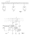
- Fig. 1 shows a power supply line with e.g. three conductors 1, 2, 3. There are two along the line Transmitter TX1, TX2 and a receiver RX1 arranged. Further Transmitter and receiver can be provided in the Figure not shown.
- Each transmitter TXi is supplied with at least one transmission signal that it should transmit.
- each transmitter TXi is supplied with a plurality of transmission signals s i1 , ... S ik , which it must transmit to the receivers RX1 .. RXk.
- the transmission signals s ij are coupled into the power supply line in the manner described below. As a result, there is usually more than one signal on the power supply line at the location of the receiver RX1.
- the task of the receiver RX1 is now to demodulate at least one of them and to provide them as an output signal S.
- the transmitters and receiver spatially separated. In practice, however e.g. another transmitter is also arranged at the receiver his. It is also conceivable that the power supply line a more complicated geometry than that in Fig. 1 has shown and e.g. Has branches. Furthermore, the Power supply line arranged so-called “line traps", which spread the PLC signals into certain parts prevent the network.
- the structure of a transmitter for example TX1, can be seen in FIG. 2.
- the transmission signals s 11 , s 12 , ... are fed to a combination circuit 4, the function of which is described below and which generates a signal 5, 6, 7 for each conductor 1, 2, 3 of the power supply line. This is coupled into the conductors 1, 2 and 3 via conventional couplers 8, 9, 10 with coupling capacitors C1, C2, C3.
- the signals of a Carrier frequency of e.g. some 100 kHz can be modulated. This can either be done before the combination circuit 4 or between the combination circuit 4 and the couplers 8, 9, 10 happen. As part of the present In particular, it is also possible that the invention different transmitters TX1, TX2 the same carrier frequency to use.
- the structure of the RX1 receiver results from Fig. 3. It takes the signals from the three conductors 1, 2, 3 via couplers 20, 21, 22 with coupling capacitors C4, C5, C6 and leads them over three lines 23, 24, 25 one Isolation circuit 26 too. In the separation circuit 26 are in the decoupled in the manner described below Received signals linked to at least one of the transmit signals to reconstruct and generate an output signal S.
- y i ⁇ y i, 1 , y i, 2 , Y i, 3 ⁇ denotes the modulation amplitudes or received signals on the individual conductors 1, 2, 3 at the receiver RXi
- y i (t) H 1, i ⁇ X 1 (t) + H 2, i ⁇ X 2nd (t) + ... + n i (t)
- H j, i denotes the transfer function between transmitter TXj and receiver RXi and n i the noise at receiver RXi.
- each transfer function H j, i is a matrix.
- TX1 emits two transmission signals, namely s 11 (the signal that the receiver RX1 is to receive) and s 12 (a signal that is directed to another receiver).
- TX2 sends a further signal s 23 , which is directed to another receiver but is also received at the location of the receiver RX1.
- the received signals y 1 can also be arithmetically processed in another way in order to determine the desired transmit signal s 11 .
- the so-called “maximum likelihood sequence estimator (MLSE)" can be used. From the measured received signals y i and the values of H i, j and w ij, which are assumed to be known, the sequence s 11 (t) for which the value of y 1 (t) - H 1.1 ⁇ W 11 ⁇ S 11 (t) 2nd is minimal.
- the best choice of the coupling weights w ij depends on the algorithm of the receiver. The choice is preferably made on the basis of a global optimization of the system, the aim of which is to minimize the error rates of the individual connections.
- the coupling weights w ij are preferably selected in a global optimization process.
- the weights can be chosen, for example, so that the expected values of the error rates of all connection paths used are minimal.
- the transfer functions H i, j can no longer be regarded as frequency-independent.
- the corresponding multiplications in the above equations can be replaced by convolution.
- the equations in the above form can be used to represent the relationships in individual frequency bands, which allows a separate treatment of each frequency band, in particular if several carrier frequencies are used.
Landscapes
- Engineering & Computer Science (AREA)
- Power Engineering (AREA)
- Computer Networks & Wireless Communication (AREA)
- Signal Processing (AREA)
- Cable Transmission Systems, Equalization Of Radio And Reduction Of Echo (AREA)
Applications Claiming Priority (2)
| Application Number | Priority Date | Filing Date | Title |
|---|---|---|---|
| DE19853348 | 1998-11-19 | ||
| DE1998153348 DE19853348A1 (de) | 1998-11-19 | 1998-11-19 | Verfahren zur Signalübertragung über Stromversorgungsleitungen |
Publications (2)
| Publication Number | Publication Date |
|---|---|
| EP1003294A2 true EP1003294A2 (fr) | 2000-05-24 |
| EP1003294A3 EP1003294A3 (fr) | 2002-05-15 |
Family
ID=7888323
Family Applications (1)
| Application Number | Title | Priority Date | Filing Date |
|---|---|---|---|
| EP99811009A Withdrawn EP1003294A3 (fr) | 1998-11-19 | 1999-11-04 | Procédé de communication sur ligne à haute tension |
Country Status (5)
| Country | Link |
|---|---|
| EP (1) | EP1003294A3 (fr) |
| CN (1) | CN1254993A (fr) |
| DE (1) | DE19853348A1 (fr) |
| NO (1) | NO995640L (fr) |
| RU (1) | RU99124404A (fr) |
Family Cites Families (9)
| Publication number | Priority date | Publication date | Assignee | Title |
|---|---|---|---|---|
| US4357598A (en) * | 1981-04-09 | 1982-11-02 | Westinghouse Electric Corp. | Three-phase power distribution network communication system |
| JPS59163696A (ja) * | 1983-03-09 | 1984-09-14 | 株式会社日本自動車部品総合研究所 | 電気配線システム |
| GB8410044D0 (en) * | 1984-04-18 | 1984-05-31 | Communications Patents Ltd | Data transmission system |
| DE3515127A1 (de) * | 1985-04-26 | 1986-10-30 | Rafi Gmbh & Co Elektrotechnische Spezialfabrik, 7981 Berg | Netzgebundene vielfachzugriffseinrichtung |
| DE4121356C2 (de) * | 1991-06-28 | 1995-01-19 | Siemens Ag | Verfahren und Einrichtung zur Separierung eines Signalgemisches |
| DE19520596A1 (de) * | 1995-06-06 | 1996-12-12 | Siemens Ag | Anordnung zum Übertragen von Daten und Energie über eine Busleitung |
| GB9616142D0 (en) * | 1996-08-01 | 1996-09-11 | Northern Telecom Ltd | Distribution network |
| DE19640223C2 (de) * | 1996-09-30 | 1998-10-22 | Siemens Ag | Verfahren zum Betreiben eines Kommunikations- und/oder Steuerungssystems sowie Kommunikations- und/oder Steuerungssystem |
| DE19815040A1 (de) * | 1998-04-03 | 1999-10-07 | Abb Research Ltd | Verfahren und Vorrichtung zur Signalübertragung über Stromversorgungsleitungen |
-
1998
- 1998-11-19 DE DE1998153348 patent/DE19853348A1/de not_active Ceased
-
1999
- 1999-11-04 EP EP99811009A patent/EP1003294A3/fr not_active Withdrawn
- 1999-11-17 NO NO995640A patent/NO995640L/no not_active Application Discontinuation
- 1999-11-18 RU RU99124404/09A patent/RU99124404A/ru not_active Application Discontinuation
- 1999-11-19 CN CN 99124478 patent/CN1254993A/zh active Pending
Also Published As
| Publication number | Publication date |
|---|---|
| CN1254993A (zh) | 2000-05-31 |
| NO995640L (no) | 2000-05-22 |
| NO995640D0 (no) | 1999-11-17 |
| DE19853348A1 (de) | 2000-05-25 |
| RU99124404A (ru) | 2001-09-27 |
| EP1003294A3 (fr) | 2002-05-15 |
Similar Documents
| Publication | Publication Date | Title |
|---|---|---|
| EP0948143B1 (fr) | Procédé et dispositif pour la communication de signaux sur lignes d'alimentation | |
| DE602004004261T2 (de) | Drahtloses lan system wobei ein zugangspunkt durch ein optisches multiplexsystem mit untergeordneten stationen verbunden ist | |
| DE2608599C3 (de) | Schaltungsanordnung zur Kompensation des durch Kreuzpolarisation dual polarisierter Wellen in einem Mikrowellen-Übertragungssystem verursachten Gegensprechens | |
| DE69429137T2 (de) | Unterdrückung von nahem Übersprechen | |
| DE10048348C2 (de) | Verfahren zur Systemsynchronisation von PLC-Systemen | |
| DE10061587B4 (de) | Anordnung und Verfahren zur Datenkommunikation in einem Energieverteilungsnetz | |
| DE1766907B2 (de) | Verfahren und schaltungsanordnung zur verschluesselten durchschaltung von nachrichten | |
| DE10061584B4 (de) | Anordnung und Verfahren zur Datenkommunikation in einem Energieverteilungsnetz | |
| DE102009014549A1 (de) | Hochfrequenzkommunikations-Vorrichtung und -Verfahren | |
| DE19850279B4 (de) | Verfahren für die Übertragung von Signalen zwischen einer ersten Funkstation und einer zweiten Funkstation und Funkstation | |
| EP1217760A1 (fr) | Appareil et méthode pour la communication de données sur un réseau de lignes d'alimentation | |
| DE68911657T2 (de) | Zugriffseinheit für einen Übertragungsweg eines lokalen Netzes. | |
| EP2802123A1 (fr) | Dispositif et procédé de transmission des données pour la fabrication de produits alimentaires | |
| DE60131365T2 (de) | Drahtloses Kommunikationssystem mit Wellenleiter | |
| DE102004030849B4 (de) | Verfahren und System zur Übertragung geheimer Daten in einem Kommunikations-Netzwerk | |
| DE602005005026T2 (de) | Sender mit vergrösserter ultrabreitband-(uwb-)benutzerkapazität unter verwendung von strahlformung | |
| EP1003294A2 (fr) | Procédé de communication sur ligne à haute tension | |
| DE3715594C2 (de) | Anordnung zum Anschluß von Ausgangs- und Eingangsstufen einer Sende/Empfangseinrichtung | |
| EP1548991B1 (fr) | Couplage de bus transformateur | |
| WO2017063897A1 (fr) | Système de communication pour un système de gestion de batteries pour une batterie et procédé d'exploitation d'au moins un réseau de couplage prédéfini d'un tel système de communication | |
| DE19849111C1 (de) | Verfahren und Schaltungsanordnung zur Datenübertragung auf Powerlines | |
| DE102009019042A1 (de) | Übertragungsgerät und System für Eisenbahnwagen | |
| DE4210023A1 (de) | Digitales Nachrichtenübertragungssystem mit elektrischen symmetrischen Zweidraht-Leitungen unter Verwendung von Phantomkreisen | |
| WO2019162005A1 (fr) | Systèmes de transport de signaux reçus de l'extérieur dans un véhicule automobile | |
| EP1374614A2 (fr) | Procede pour controler un systeme de radiotelephonie mobile |
Legal Events
| Date | Code | Title | Description |
|---|---|---|---|
| PUAI | Public reference made under article 153(3) epc to a published international application that has entered the european phase |
Free format text: ORIGINAL CODE: 0009012 |
|
| AK | Designated contracting states |
Kind code of ref document: A2 Designated state(s): AT BE CH CY DE DK ES FI FR GB GR IE IT LI LU MC NL PT SE |
|
| AX | Request for extension of the european patent |
Free format text: AL;LT;LV;MK;RO;SI |
|
| PUAL | Search report despatched |
Free format text: ORIGINAL CODE: 0009013 |
|
| AK | Designated contracting states |
Kind code of ref document: A3 Designated state(s): AT BE CH CY DE DK ES FI FR GB GR IE IT LI LU MC NL PT SE |
|
| AX | Request for extension of the european patent |
Free format text: AL;LT;LV;MK;RO;SI |
|
| RIC1 | Information provided on ipc code assigned before grant |
Free format text: 7H 04B 3/54 A, 7H 04B 3/56 B |
|
| 17P | Request for examination filed |
Effective date: 20021011 |
|
| AKX | Designation fees paid |
Designated state(s): DE ES IT |
|
| GRAP | Despatch of communication of intention to grant a patent |
Free format text: ORIGINAL CODE: EPIDOSNIGR1 |
|
| STAA | Information on the status of an ep patent application or granted ep patent |
Free format text: STATUS: THE APPLICATION IS DEEMED TO BE WITHDRAWN |
|
| 18D | Application deemed to be withdrawn |
Effective date: 20060329 |