EP1003295A2 - Filtre diplex à annulateur de flux, non saturant,pour communication par le réseau électrique - Google Patents
Filtre diplex à annulateur de flux, non saturant,pour communication par le réseau électrique Download PDFInfo
- Publication number
- EP1003295A2 EP1003295A2 EP99309216A EP99309216A EP1003295A2 EP 1003295 A2 EP1003295 A2 EP 1003295A2 EP 99309216 A EP99309216 A EP 99309216A EP 99309216 A EP99309216 A EP 99309216A EP 1003295 A2 EP1003295 A2 EP 1003295A2
- Authority
- EP
- European Patent Office
- Prior art keywords
- windings
- filter
- transformer
- primary
- capacitor
- Prior art date
- Legal status (The legal status is an assumption and is not a legal conclusion. Google has not performed a legal analysis and makes no representation as to the accuracy of the status listed.)
- Withdrawn
Links
Images


Classifications
-
- H—ELECTRICITY
- H04—ELECTRIC COMMUNICATION TECHNIQUE
- H04B—TRANSMISSION
- H04B3/00—Line transmission systems
- H04B3/54—Systems for transmission via power distribution lines
- H04B3/56—Circuits for coupling, blocking, or by-passing of signals
-
- H—ELECTRICITY
- H04—ELECTRIC COMMUNICATION TECHNIQUE
- H04B—TRANSMISSION
- H04B2203/00—Indexing scheme relating to line transmission systems
- H04B2203/54—Aspects of powerline communications not already covered by H04B3/54 and its subgroups
- H04B2203/5462—Systems for power line communications
- H04B2203/5491—Systems for power line communications using filtering and bypassing
-
- H—ELECTRICITY
- H04—ELECTRIC COMMUNICATION TECHNIQUE
- H04B—TRANSMISSION
- H04B2203/00—Indexing scheme relating to line transmission systems
- H04B2203/54—Aspects of powerline communications not already covered by H04B3/54 and its subgroups
- H04B2203/5462—Systems for power line communications
- H04B2203/5495—Systems for power line communications having measurements and testing channel
Definitions
- This invention relates to the field of filters, and more particularly to a non-saturating, flux canceling filter for power line communications.
- a filter is need at the point of entry into the home. Given the huge difference in frequency between the power line, 60Hz and the signal, greater than 1 MHz, it would appear at first sight that it should not be difficult to construct such a filter. The problem arises from the fact that the low pass filter, carrying the power supply, has to carry huge currents, up to 200 Amperes, so that to avoid saturation the core would have to be physically enormous. Given the second order relationship between heat and current, any small resistive load in the filter will translate in the generation of a large amount of heat that not only has to be dissipated, but also wastes energy.
- a power line communications filter comprising an input terminal, an output terminal, and a common terminal; a transformer having primary and secondary windings, each having one end connected to said respective input and output terminals, and another end connected to a common connection, said windings being wound on a high permeability magnetic core in such a way as to promote flux leakage and with a winding polarity such that flux cancellation occurs when current flows through said windings in series; and a capacitor between said common terminal and said common connection of said primary and secondary windings, said capacitor having a large impedance at low frequencies such that low frequency current flows through both said windings in series and flux cancellation occurs.
- the capacitor and transformer should resonate at about 1 to 5KHz. Resonance is an unwanted side effect. Since high frequency roll off begins above this frequency, it should be as low as possible without affecting operation at power line frequencies. There are some rare cases where the third harmonic power (180Hz) exceeds the fundamental power. For this reason, the filter should be essentially lossles well beyond 180 Hz (and possibly even the 5 th harmonic at 300Hz). As the frequency is moved higher, the attenuation at high frequencies is reduced.
- the transformer essentially behaves like a single piece of wire because there is effectively an open circuit between the common connection and said common terminal.
- the current flows in series through the primary and secondary windings. Due to the flux canceling configuration, the inductance of the windings is canceled out and there is near zero loss.
- the capacitor effectively provides a closed circuit and the filter behaves like a signal transformer with good roll off.
- the present invention seeks to achieve the opposite effect.
- the core geometry preferably ensures maximum physical separation of the primary and secondary coils by winding them at opposite ends of the core, and also ensures a long magnetic path. Leakage inductance increases with the length per turn, so a larger cross section can be used to increase the length of the wire.
- the magnetic core should be made of a material having a high permeability up to the operating frequency.
- a suitable choice is Fair-Rite Corp Type 43, which has a permeability factor of approximately 800 at frequencies up to 5MHz.
- the permeability should be as high as possible to achieve higher attenuation at high frequencies, reduce the number of turns to reduce the loss at low frequencies, and reduce the size, weight and cost of the unit.
- Power and communications come in from the street on line 1.
- the power is separated by the low pass filter 2 and the communications signals are separated by high pass filter 3.
- the low pass filter 2 should pass 60 Hz and the high pass filter 3 should pass signals above about 1 MHz.
- a simple low pass filter consisting of inductance 4 and capacitor 5 is shown in Figure 2.
- This simple filter is not practicable at currents of up to 200 Amps at 60 Hz because in order to avoid saturation, the core would have to be enormous in physical size.
- This problem is similar to the classic problem of having to support a DC current in a transformer, for example, a telephone current feed.
- the classic solution is to introduce an air gap and then increase the core size to compensate for the reduced permeability. This solution is not adequate in this extreme case.
- the filter shown in Figure 3 is an ordinary signal transformer having a primary inductance of about 1mH. This has primary and secondary windings 6, 7, a common line 8, and input and output lines 9, 10.
- the transformer has a frequency response as shown in Figure 4. This shows that the high frequency roll off provides about 28 dB of attenuation at 1 MHz, while the unwanted low frequency roll off is about 40 dB at 60Hz.
- the effect of adding a 0.1 ⁇ capacitor is shown in Figure 5.
- the transformer and capacitor resonate at about 5 kHz.
- the frequency response of the arrangement is essentially the same as for the transformer alone because the capacitor has a low impedance.
- the capacitor has a high impedance and the circuit behaves as if the capacitance is an open circuit.
- the current flows through both windings, which are arranged in opposition, in series. This causes flux cancellation and the filter behaves like a straight piece of wire with the inductance of the windings canceling out.
- Figure 7 shows a more complete circuit where an output capacitor 12 (0.1 ⁇ F) has been added to the power output to improve further the attenuation and a high pass filter 13 has been added to the communications output.
- the frequency response is shown in Figure 8. Fuses F1 and F2 are added in case the capacitors short.
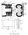
- the physical design of the circuit is shown in Figure 9.
- the filter should be small in physical size since for certain applications it is desirable to install the unit behind a conventional electricity meter.
- the primary and secondary windings 6, 7 consists of two coils of four turns each wound from a single length of wire on a separate jig.
- the wire is approximately 0.25" in diameter. This is a convenient manufacturing technique. The filter would work equally well if not wound from a single piece of wire.
- the core 15 consists of a split U-shaped core or a split toroid. It has little or no air gap.
- the core material is Fair-Rite Corp Type 43. This has a permeability factor of approximately 800 up to 5MHz. Additionally, the core 15 consists of a pair of side-by-side pieces 16, 17 . These increase the thickness of the core and thus the length of wire per turn, which increases leakage inductance.
- the core 15 shown in Figure is rectangular in shape. It has dimensions of 10cm by 7.5 cms by 2.5 cms. Of course a unitary core with appropriate dimensions can also be employed.
- the wire forming the windings 6, 7 is approximately 0.25" in diameter. It is #2 gauge and has a resistance of 0.17 ⁇ /1000ft.
- the transformer uses 3 feet of wire, giving a total resistance of 0.5m ⁇ .
- the wire is first wound into two coils of 4 turns each in opposition in a separate jig. The wire is thick enough to make the winding assembly self-supporting so that this can be slipped over the separate halves of the core 15.
- Capacitor 11 having a capacitance of at least 0.02 ⁇ F is connected between the common connecting link 20 for the windings and the ground plane.
- Capacitor 12 having a capacitance of at least 0.05 ⁇ F (0.06 ⁇ F was used in tests) is similarly connected between the output line and the ground plane.
- RF measurements showed a rejection from input to output of at least 40dB at frequencies above 3MHz whether the inductor was carrying load current or not. Additional capacitance at the output improves the rejection at the low frequency end of the high pass band, e.g. just above 1MHz..
- the described filter is essentially a short circuited transformer at RF frequencies, and the filtering provided under those conditions is governed by the transformer's leakage inductance.
- the choice of core geometry ensures maximum physical separation of the primary and secondary windings by winding them at the opposite ends of the core and also ensures a long magnetic path, which increases leakage inductance.
- Leakage inductance is also increased with the length per turn. The length of each turn is increased by using a generous core cross section. Due to the large wire diameter and the radius of the winding, the wire usage is not quite doubled, which means that resistive losses are not doubled.
- the described filter thus provides an effective means of separating communications signals from power feeds with minimal power consumption.
Landscapes
- Engineering & Computer Science (AREA)
- Power Engineering (AREA)
- Computer Networks & Wireless Communication (AREA)
- Signal Processing (AREA)
- Filters And Equalizers (AREA)
- Cable Transmission Systems, Equalization Of Radio And Reduction Of Echo (AREA)
Applications Claiming Priority (2)
| Application Number | Priority Date | Filing Date | Title |
|---|---|---|---|
| US09/195,424 US6177849B1 (en) | 1998-11-18 | 1998-11-18 | Non-saturating, flux cancelling diplex filter for power line communications |
| US195424 | 1998-11-18 |
Publications (2)
| Publication Number | Publication Date |
|---|---|
| EP1003295A2 true EP1003295A2 (fr) | 2000-05-24 |
| EP1003295A3 EP1003295A3 (fr) | 2000-09-13 |
Family
ID=22721372
Family Applications (1)
| Application Number | Title | Priority Date | Filing Date |
|---|---|---|---|
| EP99309216A Withdrawn EP1003295A3 (fr) | 1998-11-18 | 1999-11-18 | Filtre diplex à annulateur de flux, non saturant,pour communication par le réseau électrique |
Country Status (3)
| Country | Link |
|---|---|
| US (1) | US6177849B1 (fr) |
| EP (1) | EP1003295A3 (fr) |
| CA (1) | CA2290046A1 (fr) |
Cited By (4)
| Publication number | Priority date | Publication date | Assignee | Title |
|---|---|---|---|---|
| WO2000062396A1 (fr) * | 1999-04-09 | 2000-10-19 | 1061933 Ontario Inc. | Systeme attenuateur d'harmonique universel |
| WO2003044982A1 (fr) * | 2001-11-21 | 2003-05-30 | Schneider Electric Powerline Communications Ab | Dispositif coupleur |
| WO2003071709A1 (fr) * | 2002-02-22 | 2003-08-28 | Schneider Electric Powerline Communications Ab | Filtre de suppression |
| EP2424120A1 (fr) * | 2010-08-31 | 2012-02-29 | ABB Research Ltd. | Agencement de filtre de communication de ligne d'alimentation |
Families Citing this family (61)
| Publication number | Priority date | Publication date | Assignee | Title |
|---|---|---|---|---|
| DE19926699C2 (de) * | 1999-06-11 | 2003-10-30 | Vacuumschmelze Gmbh | Hochpaßzweig einer Frequenzweiche für ADSL-Systeme |
| BR9917572A (pt) | 1999-12-08 | 2002-08-06 | Ascom Powerline Comm Ag | Disposição para a transmissão de informações através de uma rede de suprimento de corrente-baixa tensão |
| MXPA02007139A (es) | 2000-01-20 | 2004-09-06 | Current Tech Llc | Metodo para aislar datos en una red de comunicaciones con linea de energia. |
| US7176786B2 (en) * | 2000-01-20 | 2007-02-13 | Current Technologies, Llc | Method of isolating data in a power line communications network |
| US6998962B2 (en) | 2000-04-14 | 2006-02-14 | Current Technologies, Llc | Power line communication apparatus and method of using the same |
| KR20030019349A (ko) * | 2000-04-14 | 2003-03-06 | 커런트 테크놀로지스, 엘엘씨 | 중간 전압 전력 분배선을 사용한 디지털 통신 |
| US6965302B2 (en) * | 2000-04-14 | 2005-11-15 | Current Technologies, Llc | Power line communication system and method of using the same |
| US7103240B2 (en) | 2001-02-14 | 2006-09-05 | Current Technologies, Llc | Method and apparatus for providing inductive coupling and decoupling of high-frequency, high-bandwidth data signals directly on and off of a high voltage power line |
| US7248148B2 (en) * | 2000-08-09 | 2007-07-24 | Current Technologies, Llc | Power line coupling device and method of using the same |
| US6980089B1 (en) | 2000-08-09 | 2005-12-27 | Current Technologies, Llc | Non-intrusive coupling to shielded power cable |
| US7245201B1 (en) * | 2000-08-09 | 2007-07-17 | Current Technologies, Llc | Power line coupling device and method of using the same |
| MXPA03005313A (es) * | 2000-12-15 | 2004-03-26 | Current Tech Llc | Comunicacion de datos de fibra optica con sistemas de potencia electrica. |
| EP1371219A4 (fr) | 2001-02-14 | 2006-06-21 | Current Tech Llc | Communication de donnees par ligne electrique |
| US7053756B2 (en) * | 2001-12-21 | 2006-05-30 | Current Technologies, Llc | Facilitating communication of data signals on electric power systems |
| US7199699B1 (en) | 2002-02-19 | 2007-04-03 | Current Technologies, Llc | Facilitating communication with power line communication devices |
| AU2003237292A1 (en) * | 2002-05-31 | 2003-12-19 | Polyphaser Corporation | Circuit for diverting surges and transient impulses |
| US7102478B2 (en) * | 2002-06-21 | 2006-09-05 | Current Technologies, Llc | Power line coupling device and method of using the same |
| US6982611B2 (en) | 2002-06-24 | 2006-01-03 | Current Technologies, Llc | Power line coupling device and method of using the same |
| US7132819B1 (en) | 2002-11-12 | 2006-11-07 | Current Technologies, Llc | Floating power supply and method of using the same |
| US7076378B1 (en) | 2002-11-13 | 2006-07-11 | Current Technologies, Llc | Device and method for providing power line characteristics and diagnostics |
| US6737935B1 (en) | 2002-12-03 | 2004-05-18 | John Mezzalingua Associates, Inc. | Diplex circuit forming bandstop filter |
| US6980091B2 (en) * | 2002-12-10 | 2005-12-27 | Current Technologies, Llc | Power line communication system and method of operating the same |
| US7075414B2 (en) * | 2003-05-13 | 2006-07-11 | Current Technologies, Llc | Device and method for communicating data signals through multiple power line conductors |
| US6965303B2 (en) * | 2002-12-10 | 2005-11-15 | Current Technologies, Llc | Power line communication system and method |
| US6980090B2 (en) * | 2002-12-10 | 2005-12-27 | Current Technologies, Llc | Device and method for coupling with electrical distribution network infrastructure to provide communications |
| US7064654B2 (en) * | 2002-12-10 | 2006-06-20 | Current Technologies, Llc | Power line communication system and method of operating the same |
| US7046124B2 (en) * | 2003-01-21 | 2006-05-16 | Current Technologies, Llc | Power line coupling device and method of using the same |
| JP4271474B2 (ja) * | 2003-03-28 | 2009-06-03 | Tdk株式会社 | 電力線終端回路および方法、ならびに電力線中継装置 |
| US7308103B2 (en) | 2003-05-08 | 2007-12-11 | Current Technologies, Llc | Power line communication device and method of using the same |
| US7460467B1 (en) | 2003-07-23 | 2008-12-02 | Current Technologies, Llc | Voice-over-IP network test device and method |
| US7113134B1 (en) | 2004-03-12 | 2006-09-26 | Current Technologies, Llc | Transformer antenna device and method of using the same |
| US8040235B2 (en) * | 2005-04-08 | 2011-10-18 | Panasonic Corporation | Relay apparatus and electric appliance |
| US7714682B2 (en) * | 2007-06-21 | 2010-05-11 | Current Technologies, Llc | Power line data signal attenuation device and method |
| US8027136B2 (en) * | 2007-10-18 | 2011-09-27 | Transtector Systems, Inc. | Surge suppression device having one or more rings |
| US7944670B2 (en) * | 2007-10-30 | 2011-05-17 | Transtector Systems, Inc. | Surge protection circuit for passing DC and RF signals |
| WO2009142657A1 (fr) * | 2008-05-19 | 2009-11-26 | Polyphaser Corporation | Suppresseur de surtensions à large bande laissant passer le courant continu et les radiofréquences |
| ES2378585T3 (es) * | 2008-08-20 | 2012-04-16 | Sony Corporation | Dispositivo para determinar una señal de modo común en una red de comunicaciones sobre línea eléctrica |
| DE102009012600B3 (de) * | 2009-03-11 | 2010-10-28 | Erbe Elektromedizin Gmbh | Hochfrequenzchirurgiegenerator |
| CN102742101A (zh) * | 2009-10-02 | 2012-10-17 | 特兰斯泰克塔系统公司 | 带有非线性保护装置的rf共轴浪涌保护器 |
| US8400760B2 (en) * | 2009-12-28 | 2013-03-19 | Transtector Systems, Inc. | Power distribution device |
| WO2011119723A2 (fr) * | 2010-03-26 | 2011-09-29 | Transtector Systems, Inc. | Dispositif de protection contre les surtensions ethernet |
| US8441795B2 (en) | 2010-05-04 | 2013-05-14 | Transtector Systems, Inc. | High power band pass RF filter having a gas tube for surge suppression |
| US20110271802A1 (en) | 2010-05-04 | 2011-11-10 | Edward Honig | Double handle tool |
| CA2798891C (fr) | 2010-05-11 | 2016-04-12 | Transtector Systems, Inc. | Protecteur rf laissant passer le continu et muni d'un module limiteur de surcharge |
| US8611062B2 (en) | 2010-05-13 | 2013-12-17 | Transtector Systems, Inc. | Surge current sensor and surge protection system including the same |
| US8976500B2 (en) | 2010-05-26 | 2015-03-10 | Transtector Systems, Inc. | DC block RF coaxial devices |
| US8730637B2 (en) | 2010-12-17 | 2014-05-20 | Transtector Systems, Inc. | Surge protection devices that fail as an open circuit |
| WO2013120101A1 (fr) | 2012-02-10 | 2013-08-15 | Transtector Systems, Inc. | Circuit suppresseur ou de protection contre les surtensions à tension résiduelle transitoire réduite |
| US9048662B2 (en) | 2012-03-19 | 2015-06-02 | Transtector Systems, Inc. | DC power surge protector |
| US9190837B2 (en) | 2012-05-03 | 2015-11-17 | Transtector Systems, Inc. | Rigid flex electromagnetic pulse protection device |
| US9124093B2 (en) | 2012-09-21 | 2015-09-01 | Transtector Systems, Inc. | Rail surge voltage protector with fail disconnect |
| WO2015017339A1 (fr) * | 2013-07-29 | 2015-02-05 | Enphase Energy, Inc. | Filtre de compatibilité électromagnétique comportant une interface intégrée de transmissions sur courant porteur |
| US10129993B2 (en) | 2015-06-09 | 2018-11-13 | Transtector Systems, Inc. | Sealed enclosure for protecting electronics |
| US10588236B2 (en) | 2015-07-24 | 2020-03-10 | Transtector Systems, Inc. | Modular protection cabinet with flexible backplane |
| US10356928B2 (en) | 2015-07-24 | 2019-07-16 | Transtector Systems, Inc. | Modular protection cabinet with flexible backplane |
| US9924609B2 (en) | 2015-07-24 | 2018-03-20 | Transtector Systems, Inc. | Modular protection cabinet with flexible backplane |
| WO2017075286A1 (fr) | 2015-10-27 | 2017-05-04 | Transtector Systems, Inc. | Parasurtenseur radiofréquence avec forme de cavité piston-vérin adaptée |
| US9991697B1 (en) | 2016-12-06 | 2018-06-05 | Transtector Systems, Inc. | Fail open or fail short surge protector |
| US10756638B2 (en) * | 2018-07-02 | 2020-08-25 | Ford Global Technologies, Llc | Transformer based variable voltage converter |
| EP3800794B1 (fr) | 2019-09-30 | 2025-12-17 | Solaredge Technologies Ltd. | Annulation de flux magnétique pour communication par ligne électrique |
| CN113189387A (zh) * | 2021-05-07 | 2021-07-30 | 湖南银河电气有限公司 | 低频电流电桥和电流比较仪 |
Family Cites Families (6)
| Publication number | Priority date | Publication date | Assignee | Title |
|---|---|---|---|---|
| US1481945A (en) * | 1921-03-03 | 1924-01-29 | Rca Corp | Radio receiving system |
| DE2521810A1 (de) * | 1975-05-16 | 1976-11-25 | Bosch Gmbh Robert | Hochfrequenz-bandfilter mit mindestens zwei resonanzkreisen |
| DE2638182A1 (de) * | 1976-08-25 | 1978-03-09 | Bosch Gmbh Robert | Weiche fuer eine hochfrequenzleitung zur zufuehrung und entnahme einer hochfrequenz und eines versorgungstroms |
| DE3545405A1 (de) * | 1985-12-19 | 1987-07-02 | Siemens Ag | Schaltungsanordnung fuer einen einphasen-sperrfilter (breitbandsperre) |
| DE3888750T2 (de) | 1987-08-07 | 1994-07-14 | Mitsui Petrochemical Ind | Vorrichtung und Verfahren zum Diskriminieren von Signalen. |
| AUPO440796A0 (en) | 1996-12-24 | 1997-01-23 | United Energy Ltd. | A termination circuit |
-
1998
- 1998-11-18 US US09/195,424 patent/US6177849B1/en not_active Expired - Fee Related
-
1999
- 1999-11-18 EP EP99309216A patent/EP1003295A3/fr not_active Withdrawn
- 1999-11-18 CA CA002290046A patent/CA2290046A1/fr not_active Abandoned
Cited By (5)
| Publication number | Priority date | Publication date | Assignee | Title |
|---|---|---|---|---|
| WO2000062396A1 (fr) * | 1999-04-09 | 2000-10-19 | 1061933 Ontario Inc. | Systeme attenuateur d'harmonique universel |
| WO2003044982A1 (fr) * | 2001-11-21 | 2003-05-30 | Schneider Electric Powerline Communications Ab | Dispositif coupleur |
| WO2003071709A1 (fr) * | 2002-02-22 | 2003-08-28 | Schneider Electric Powerline Communications Ab | Filtre de suppression |
| EP2424120A1 (fr) * | 2010-08-31 | 2012-02-29 | ABB Research Ltd. | Agencement de filtre de communication de ligne d'alimentation |
| WO2012028342A1 (fr) * | 2010-08-31 | 2012-03-08 | Abb Research Ltd | Agencement de filtres de communication par courants porteurs en ligne |
Also Published As
| Publication number | Publication date |
|---|---|
| US6177849B1 (en) | 2001-01-23 |
| EP1003295A3 (fr) | 2000-09-13 |
| CA2290046A1 (fr) | 2000-05-18 |
Similar Documents
| Publication | Publication Date | Title |
|---|---|---|
| US6177849B1 (en) | Non-saturating, flux cancelling diplex filter for power line communications | |
| US5640314A (en) | Symmetrical power system | |
| EP0684679B1 (fr) | Méthode pour la réduction de la distorsion de la forme de l'onde en un dispositif électrique et circuit pour un dispositif électrique | |
| US5541482A (en) | Electrodeless discharge lamp including impedance matching and filter network | |
| US4264827A (en) | Current mode data or power bus | |
| US6130645A (en) | Combination wide band antenna and heating element on a window of a vehicle | |
| JPH07504556A (ja) | 一体化されたemi/rfiフィルタ磁気装置 | |
| MXPA05003903A (es) | Filtro para la segmentacion de lineas de energia para comunicaciones. | |
| US6278266B1 (en) | Symmetrical power generator and method of use | |
| EP0468509A2 (fr) | Circuit d'adaptation | |
| CA1291531C (fr) | Filtre sur embranchement de distribution de courant alternatif | |
| US5663636A (en) | Method for reducing waveform distortion in an electrical utility system and circuit for an electrical utility system | |
| JP4380221B2 (ja) | インピーダンス改善器具 | |
| JP2001503201A (ja) | インダクタ | |
| HK1030111A (en) | Non-saturating, flux cancelling diplex filter for power line communications | |
| CN217486380U (zh) | 一种消除电快速瞬变脉冲群干扰的滤波装置 | |
| KR200187624Y1 (ko) | 노이즈 필터가 내장된 전원 플러그 | |
| RU2143784C1 (ru) | Широкополосное устройство присоединения с направленными свойствами | |
| KR102589292B1 (ko) | 전자기 간섭 필터 | |
| CN220553353U (zh) | 滤波器 | |
| EP0641510A1 (fr) | Lampe a decharge sans electrodes comportant un reseau d'adaptation d'impedance et de filtrage | |
| NZ544998A (en) | Supply-line filter | |
| CN212034093U (zh) | 一种轨道电路防护盒及防护系统 | |
| CN87103749A (zh) | 电气变换器 | |
| JPH0677756A (ja) | ノイズフィルタ |
Legal Events
| Date | Code | Title | Description |
|---|---|---|---|
| PUAI | Public reference made under article 153(3) epc to a published international application that has entered the european phase |
Free format text: ORIGINAL CODE: 0009012 |
|
| AK | Designated contracting states |
Kind code of ref document: A2 Designated state(s): AT BE CH CY DE DK ES FI FR GB GR IE IT LI LU MC NL PT SE |
|
| AX | Request for extension of the european patent |
Free format text: AL;LT;LV;MK;RO;SI |
|
| PUAL | Search report despatched |
Free format text: ORIGINAL CODE: 0009013 |
|
| AK | Designated contracting states |
Kind code of ref document: A3 Designated state(s): AT BE CH CY DE DK ES FI FR GB GR IE IT LI LU MC NL PT SE |
|
| AX | Request for extension of the european patent |
Free format text: AL;LT;LV;MK;RO;SI |
|
| 17P | Request for examination filed |
Effective date: 20010309 |
|
| AKX | Designation fees paid |
Free format text: AT BE CH CY DE DK ES FI FR GB GR IE IT LI LU MC NL PT SE |
|
| RAP1 | Party data changed (applicant data changed or rights of an application transferred) |
Owner name: ONELINE AG |
|
| STAA | Information on the status of an ep patent application or granted ep patent |
Free format text: STATUS: THE APPLICATION IS DEEMED TO BE WITHDRAWN |
|
| 18D | Application deemed to be withdrawn |
Effective date: 20030531 |
|
| REG | Reference to a national code |
Ref country code: HK Ref legal event code: WD Ref document number: 1030111 Country of ref document: HK |